manuals.online logo
Brands
  1. Home
  2. •
  3. Brands
  4. •
  5. Weider
  6. •
  7. Home Gym
  8. •
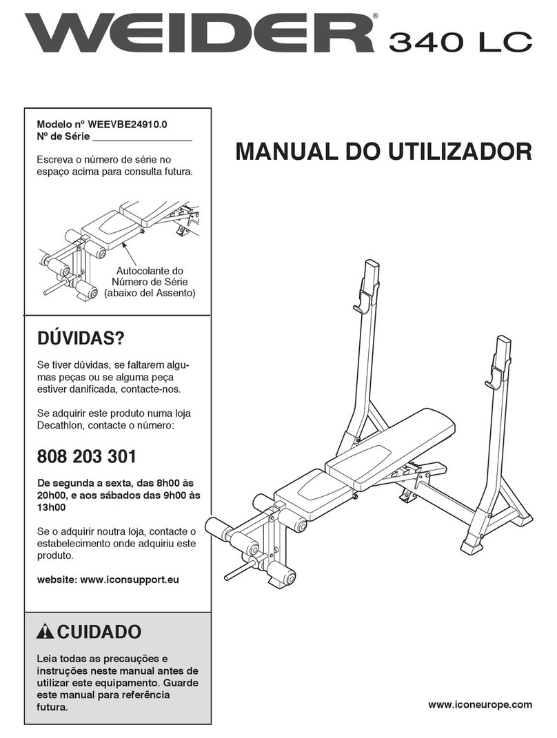
  9. Weider 340 L User manual

Weider 340 L User manual

This manual suits for next models

2

Other Weider Home Gym manuals

Weider WEBE05590 User manual

Weider

Weider WEBE05590 User manual

Weider 244 Bench Quick start guide

Weider

Weider 244 Bench Quick start guide

Weider 1112 User manual

Weider

Weider 1112 User manual

Weider XRS 20 User manual

Weider

Weider XRS 20 User manual

Weider WESY17010 User manual

Weider

Weider WESY17010 User manual

Weider 234 User manual

Weider

Weider 234 User manual

Weider 8970 User guide

Weider

Weider 8970 User guide

Weider WEBE37330 User manual

Weider

Weider WEBE37330 User manual

Weider 9300 PRO User manual

Weider

Weider 9300 PRO User manual

Weider PRO 4250 User manual

Weider

Weider PRO 4250 User manual

Weider Easy Compact 90 Quick start guide

Weider

Weider Easy Compact 90 Quick start guide

Weider 9900i User manual

Weider

Weider 9900i User manual

Weider 190 Tc Bench User manual

Weider

Weider 190 Tc Bench User manual

Weider 9015 User manual

Weider

Weider 9015 User manual

Weider 831.150290 User manual

Weider

Weider 831.150290 User manual

Weider WEEVBE33110 User manual

Weider

Weider WEEVBE33110 User manual

Weider PRO 4850 User manual

Weider

Weider PRO 4850 User manual

Weider E8001 User manual

Weider

Weider E8001 User manual

Weider Pro 137 Bench User manual

Weider

Weider Pro 137 Bench User manual

Weider Club 290 W Bench User manual

Weider

Weider Club 290 W Bench User manual

Weider WESY19610 User manual

Weider

Weider WESY19610 User manual

Weider 150722 User manual

Weider

Weider 150722 User manual

Weider C90master Blaster Bench User manual

Weider

Weider C90master Blaster Bench User manual

Weider WEBE96490 User manual

Weider

Weider WEBE96490 User manual

Popular Home Gym manuals by other brands

T.D.S. 3501 Assembly instructions

T.D.S.

T.D.S. 3501 Assembly instructions

Body Solid EXM1950 Assembly instructions

Body Solid

Body Solid EXM1950 Assembly instructions

Horizon Fitness OXFORD 6 manual

Horizon Fitness

Horizon Fitness OXFORD 6 manual

Energetics Multi Trainer 5.1 owner's manual

Energetics

Energetics Multi Trainer 5.1 owner's manual

Precor Discovery Series owner's manual

Precor

Precor Discovery Series owner's manual

Matrix MG-PL Series Service manual

Matrix

Matrix MG-PL Series Service manual

Reebok Tbr2i Manuale d'istruzioni

Reebok

Reebok Tbr2i Manuale d'istruzioni

Pure Fitness 8526HE owner's manual

Pure Fitness

Pure Fitness 8526HE owner's manual

Bowflex Sport 001-6961 Assembly instructions

Bowflex

Bowflex Sport 001-6961 Assembly instructions

NordicTrack E8200 Competition Bench Bedienungsanleitung

NordicTrack

NordicTrack E8200 Competition Bench Bedienungsanleitung

Insportline RW600 user manual

Insportline

Insportline RW600 user manual

Body Solid GHYP-345 owner's manual

Body Solid

Body Solid GHYP-345 owner's manual

Evo TAHOE 5105 user manual

Evo

Evo TAHOE 5105 user manual

ParaBody 40 Assembly instructions

ParaBody

ParaBody 40 Assembly instructions

JLL Ventus Pro Air Power instruction manual

JLL

JLL Ventus Pro Air Power instruction manual

Trojan Colorado 370 user manual

Trojan

Trojan Colorado 370 user manual

Tunturi R25 owner's manual

Tunturi

Tunturi R25 owner's manual

Deltech Fitness DF102 Assembly instructions

Deltech Fitness

Deltech Fitness DF102 Assembly instructions

manuals.online logo
manuals.online logoBrands
  • About & Mission
  • Contact us
  • Privacy Policy
  • Terms and Conditions

Copyright 2025 Manuals.Online. All Rights Reserved.

4-
Model No. 831.15925.2
Serial No.
Write the serial number in the
space above for future reference.
Serial Number Decal
(under the seat)
• Assembly
•Operation
• Maintenance
• Part List and Drawing
Sears, Roebuck and Co.
Hoffman Estates, IL 60179
WEIGHT BENCH EXERCISER
User's Manual
TABLE OF CONTENTS
WARNING DECAL PLACEMENT .............................................................. 2
IMPORTANT PRECAUTIONS ................................................................ 3
BEFORE YOU BEGIN ...................................................................... 4
PART IDENTIFICATION CHART .............................................................. 5
ASSEMBLY .............................................................................. 6
ADJUSTMENT ........................................................................... 11
EXERCISE GUIDELINES .................................................................. 13
PART LIST .............................................................................. 14
EXPLODED DRAWING .................................................................... 15
ORDERING REPLACEMENT PARTS .................................................. Back Cover
90 DAY FULL WARRANTY .......................................................... Back Cover
WARNING DECAL PLACEMENT
This drawing shows the location(s) of the warning decal(s).
If a decal is missing or illegible, call 1-877-992-5999
and request a free replacement decal. Apply the decal
in the location shown. Note: The decal(s) may not be
shown at actual size.
Crutch and spotters
must be used in the
forward position.
• Misuse of this machine may result in serious injury.
=Read user's manua| prior to use and follow a|| warnings
and instructions.
•Do not a|low children on or around machine.
and hair free and clear of
Keep body, c|othing,
o
a|| moving parts. . . _ _ "!
_llegible, or removed.
User Weight: Max 300 LBS
Weight Crutch: Max 210 LBS
Leg Developer: Max 130 LBS
Weight Carriage: Max 130 LBS
Chest Fly Per Arm: Max 40 LBS
Product may not offer aft listed exercises.
2
iMPORTANT PRECAUTIONS
WARNING: Toreducethe.skofse.ousnjory,reada,important precautions and
instructions in this manual and all warnings on the weight bench before using the weight bench.
Sears assumes no responsibility for personal injury or property damage sustained by or through
the use of this product.
.
.
=
.
5.
.
,
.
Before beginning any exercise program,
consult your physician. This is especially
important for persons over age 35 or per-
sons with pre-existing health problems.
Use the weight bench only as described in
this manual.
it is the responsibility of the owner to
ensure that all users of the weight bench
are adequately informed of all precau-
tions.
The weight bench is intended for home
use only. Do not use the weight bench in a
commercial, rental, or institutional setting.
Keep the weight bench indoors, away from
moisture and dust. Do not put the weight
bench in agarage or covered patio, or near
water.
Place the weight bench on alevel surface,
with a mat beneath it to protect the floor or
carpet. Make sure that there is enough dear-
ance around the weight bench to mount,
dismount, and use it.
inspect and properly tighten all parts regu-
larly. Replace any worn parts immediately.
The weight bench is designed to support a
maximum user weight of 300 Ibs. (136 kg)
and a maximum total weight of 510 Ibs (231
kg). Do not place more than 210 Ibs (95 kg),
including a barbell, on the weight rests. Do
.
10.
11.
12.
13.
14.
15.
16.
not place more than 130 Ibs (59 kg) on the
leg lever. Note: The weight bench does not
include abarbell or weights.
Always keep children under age 12 and
pets away from the weight bench.
Wear appropriate clothes while exercising;
do not wear loose clothes that could become
caught on the weight bench. Wear athletic
shoes for foot protection while exercising.
Always keep hands and feet away from mov-
ing parts.
Before you use the weight bench, make sure
that the backrest brace is fully inserted into
a slot in the frame.
Before you use the weight rests, make sure
that the weight rest pins are fully inserted
through the weight rests and through the
uprights.
Do not use a barbell that is longer than 6 ft.
(1.8 m) with the weight bench.
Always exercise with apartner. When you
perform the bench press exercise, your part-
ner should stand behind you to catch the
barbell if you cannot complete arepetition.
Over exercising may result in serious injury
or death. If you feel faint or if you experience
pain while exercising, stop immediately and
cool down.
3
BEFORE YOU BEGIN
Thank you for selecting the versatile WELDER PRO TM
340 L Mid-width weight bench. The 340 L Mid-width
weight bench offers a selection of exercise stations
designed to develop the major muscle groups of the
body. Whether your goal is to tone your body, build
dramatic muscle size and strength, or improve your
cardiovascular system, the weight bench will help you
to achieve the specific results you want.
For your benefit, read this manual carefully before
using the weight bench. If you have questions after
reading this manual, please see the back cover of this
manual. To help us assist you, note the product model
number and serial number before contacting us. The
model number and the location of the serial number
decal are shown on the front cover of this manual.
Before reading further, please review the drawing
below and familiarize yourself with the parts that are
labeled.
Upright
Weight Rest !_
Curl Pad
Leg Lever
Weight Clip
Weight Tube
ASSEMBLED DIMENSIONS:
Height: 4 ft. 6 in. (138 cm)
Width: 3 ft. 4 in. (101 cm)
Depth: 6 ft. 1 in. (185 cm)
Weight Rest Pin
Backrest
Backrest Brace
Seat
Curl Post Knob
4
PART iDENTiFiCATiON CHART
Refer to the drawings below to identify small parts used in assembly. The number in parentheses by each draw-
ing is the key number of the part, from the PART LIST near the end of this manual. IMPORTANT: If you cannot
find a part in the hardware kit, check to see if it has been preassembled. If a part is missing, please call
1=877=992=5999. To avoid damaging parts, do not use power tools for assembly.
N
M6 Washer (42)
M8 Washer (48)
M8 Curved
Washer (33)1
M10 Washer (35)
M8 x 16mm
Screw (26)
M10 x 18mm
Screw (36)
M8 Locknut
(31)
M10 Locknut
(37)
ST4.2 x
16mm
Screw (17)
M6 x 25mm Screw (39)
-)
M10 x 45mm Carriage Bolt (40)
M6 x 48mm Screw (41)
M8 x 48mm Screw (47)
M8 x 63mm Bolt (38)
M10 x 70mm Carriage Bolt (34)
I
MIO x 82mm Bolt (45)
q
M8 x 83mm Bolt (44)
03
m
©
r_
E
E
o
oo
*r-
X
c)
Z
5
ASSEMBLY
Assembly requires two persons.
Because of its size and weight, assemble the
weight bench in the location where it will be
used. Make sure that there is enough clear-
ance to walk around the weight bench as you
assemble it.
Place all parts in a cleared area and remove
the packing materials. Do not dispose of the
packing materials until you complete all
assembly steps.
To identify small parts, see page 5.
The following tools (not included) may be
required for assembly:
two adjustable wrenches
one standard screwdriver
one Phillips screwdriver _===_
Assembly will be more convenient if you have a
socket set, a set of open-end or closed-end
wrenches, or a set of ratchet wrenches.
,
Orient the Front Stabilizer (2) so that the
indented square holes face the floor.
Attach the Front Leg (4) to the Front Stabilizer
(2) with two M10 x 70mm Carriage Bolts (34)
and two M10 Locknuts (37). Do not tighten the
Locknuts yet.
Tighten an M8 x 48mm Screw (47) with an M8
Washer (48) into the Front Stabilizer (2) and the
Front Leg (4). Do not tighten the Screw yet. Square
Holes ,,
Y
34
6
.Attach the Front Leg (4) to the Frame (1) with
two M8 x 63mm Bolts (38), two M8 Curved
Washers (33), and two M8 Locknuts (31). Do
not tighten the Locknuts yet. 4
33
31
.%31
.Orient the Rear Stabilizer (3) so that the warn-
ing decals are facing upward.
Attach the Rear Stabilizer (3) to the Frame (1)
with two M10 x 45mm Carriage Bolts (40) and
two M10 Locknuts (37).
See step 1. Tighten the MIO Locknuts (37)
and the M8 × 48mm Screw (47).
See step 2. Tighten the M8 Locknuts (31).
Warning
Decals
37
40
3
.Orient the Seat (18) as shown.
Attach the Seat (18) to the Frame (1) with four
M6 x 25mm Screws (39).
18
39
7
5. 5
Orient the Backrest Frames (16) so that the
welded tubes are in the positions shown.
Apply a small amount of the included grease to
an M10 x 180mm Bolt (43). Attach the Backrest
Brace (15) to the Backrest Frames (16) with the
Bolt, two M10 Washers (35), and an M10
Locknut (37). Do not tighten the Locknut yet.
Orient the Backrest (19) as shown.
Attach the Backrest (19) to the Backrest
Frames (16) with four M6 x 48mm Screws (41)
and four M6 Washers (42). Do not tighten the
Screws yet.
43
Grease
19
16
35
_37
.Apply a small amount of grease to an M10 x
180mm Bolt (43), Attach the Backrest Frames
(16) to the Frame (1) with the Bolt, two M10
Washers (35), and an M10 Locknut (37), Do
not overtighten the Locknut; the Backrest
Frames should pivot easily.
Insert the end of the Backrest Brace (15)into
one of the slots in the Frame (1).
See step 5. Tighten the M10 Locknut (37)
and the four M6 × 48ram Screws (41). Do not
overtighten the Locknut; the Backrest Brace
(15) should pivot easily.
43
Grease
35
.Apply a small amount of grease to an M10 x
82mm Bolt (45), Attach the Leg Lever (5) to the
Front Leg (4) with the Bolt and an M10 Locknut
(37). Do not overtighten the Locknut; the
Leg Lever should pivot easily.
Attach the Weight Clip (8) to the weight tube on
the Leg Lever (5).
5
37
8
8. 8 23
Insert a Pad Tube (21) through the Front Leg
(4).
Slide two Foam Pads (22) onto the Pad Tube
(21). Then, press two Pad Caps (23) into the
ends of the Pad Tube.
Attach the remaining Pad Tubes (not
shown), Foam Pads (22), and Pad Caps (23)
to the Leg Lever (5) in the same way.
5
22
23 23
21
22
9. Attach the Curl Pad (20) to the Curl Post (6)
with two M6 x 25mm Screws (39). 20
10. Insert the Curl Post (6) into the Front Leg (4).
Tighten the Curl Post Knob (24) into the Front
Leg and into one of the adjustment holes in the
Curl Post. Make sure that the Curl Post Knob
is inserted through one of the adjustment
holes.
10
9
11. Insert a Base Stabilizer (9) into the Base (7).
Attach the Base Stabilizer with five M10 x
18mm Screws (36) and five M10 Washers (35).
Attach the other Base Stabilizer (9) to the
Base (7) in the same way.
11
36 36
35 36
12. Slide one of the Uprights (11) onto the Base (7).
Attach the Upright with an M8 x 83mm Bolt
(44), an M8 Locknut (31), four M8 x 16mm
Screws (26), and six M8 Curved Washers (33).
Attach the other Upright (11) to the Base (7)
in the same way.
/11
7
o
o
o
o
o
o
o
o
33 26
44
13. Attach the tether on a Weight Rest Pin (13) to
the underside of a Weight Rest (12) with an
ST4.2 x 16mm Screw (17).
Hold the Weight Rest (12) on the indicated
side of an Upright (11), and align the Weight
Rest with one of the adjustment holes in the
Upright. Insert the Weight Rest Pin (13) through
the Weight Rest and the Upright.
Attach the other Weight Rest (12) to the
other Upright (11) in the same way. Attach
both Weight Rests at the same height.
14. Make sure that all parts are properly tight-
ened before you use the weight bench.
13
10