Weidmüller LAN USB TESTER User manual

R.T.Nr. 4342660000/00/08.07
e-mail: info@weidmueller.com
www. weidmueller.com
Bedienungsanleitung
LAN/USB
Multi-Modularer Kabeltester
Operating instructions
LAN/USB
Multi-modular Cable Tester
Mode d’emploi
Testeur de câble RLE/USB
multi-modulaire
Istruzioni per l’uso
Tester multimodulare per cavi
LAN/USB
Instrucciones de empleo
LAN/USB
Comprobador de cables
multimodular

2
DEUTSCH
Gerätebeschreibung
LED POWER on/off
LED Anzeige für Auto Scan
RX Anschluss RJ 45
LED Display für RX
LED Display für TX
TX Anschluss USB Typ A
TX Anschluss RJ 45
TX Anschluss USB Typ B
RX Anschluss USB Typ A
Schalter Ein/Test/Auto
Taster für „Step-by-Step“ Modus
Batteriefach
Remote RX Anschluss USB Typ A
Remote LED Display für RX
Remote RX Anschluss RJ 45
Sicherheitshinweise
HINWEIS
Lesen Sie diese Bedienungsanlei-
tung aufmerksam und vollständig zu
Ende durch, bevor Sie das Messge-
rät bedienen.
Bevor Sie mit dem Messen begin-
nen, lesen Sie bitte die Sicherheits-
hinweise.
1
2
3
4
5
6
7
8
9
10
11
12
13
14
15
6 7 8
13
5
3
2
1
15
9
10
11
12
14
4

3
VORSICHT
Prüfen Sie vor dem Messen immer,
ob das Gerät beschädigt ist, starke
Verschmutzungen (z.B. Schmierstoffe
etc.) aufweist oder anderweitig de-
fekt ist. Kontrollieren Sie die Prüei-
tungen auf Bruch oder defekte Isola-
tion. Sollte Ihnen irgendetwas unge-
wöhnlich vorkommen, benutzen Sie
das Gerät nicht.
Multimeter bei geöffnetem Gehäuse
oder offener Batterieabdeckung nicht
benutzen.
VORSICHT
Elektrorauschen oder elektromagne-
tische Felder in der Nähe des Gerätes
können den elektrischen Kreis be-
einträchtigen. Messgeräte reagieren
auch auf unerwünschte Störsignale
im Messkreis. Um irreführende Ergeb-
nisse zu vermeiden, sollten Anwender
daher bei Messungen in der Nähe von
elektromagnetischen Störungen, mit
Sorgfalt vorgehen und entsprechende
Maßnahmen ergreifen.
WARNUNG
Das Messen von Spannungen, wel-
che die zugelassene Höchstspan-
nung überschreiten, kann zur Be-
schädigung des Messgeräts führen
und den Anwender der Gefahr eines
Stromschlags aussetzen. Beachten
Sie dazu stets die auf der Vorderseite
des Gerätes aufgedruckte zulässige
Höchstspannung.

4
Recycling nach WEEE
Entsorgung BtoC
Sehr geehrter Kunde, mit dem Erwerb unseres
Produktes haben Sie die Möglichkeit, das Gerät
nach Ende seines Lebenszyklus kostenfrei dem
Recyclingprozess zukommen zuzuführen.
Die WEEE (EU-Richtlinie 2002/96 EG)
regelt die Rücknahme und das Recy-
cling von Elektroaltgeräten. Im B2C-
Bereich (Business to Customer) sind
die Hersteller von Elektrogeräten ab
dem 13.8.2005 dazu verpichtet, Elektrogeräte
die nach diesem Datum verkauft werden, kosten-
frei zurückzunehmen und zu recyceln. Elektroge-
räte dürfen dann nicht mehr in die „normalen“ Ab-
fallströme eingebracht werden. Elektrogeräte
sind separat zu recyceln und zu entsorgen.
Alle Geräte, die unter diese Richtlinie fallen, sind
mit diesem Logo gekennzeichnet.
Was müssen Sie tun?
Nachdem Ihr Gerät sein Lebensende erreicht
hat, bringen Sie ihr Gerät einfach zur nächsten
öffentlichen Sammelstelle für Elektroaltgeräte.
Wir übernehmen dann alle anfallenden Recy-
cling- und Entsorgungsmaßnahmen. Ihnen ent-
stehen dadurch keine Kosten.

5
Instandhaltung + Batterie ersetzen
Die Instandhaltung besteht aus regelmäßigem
Reinigen sowie Ersetzen der Batterie. Das Äu-
ßere des Messgeräts kann mit einem sauberen,
trockenen Putzlappen gereinigt werden, um Öl,
Schmiermittel oder Dreck zu entfernen. Verwen-
den Sie niemals üssiges Lösemittel oder Reini-
gungsmittel.
WARNUNG
Um die Gefahr eines Stromschlags
zu vermeiden, klemmen Sie sowohl
die Prüeitungen als auch jegliche
Quelle eines Eingangssignals ab, be-
vor Sie die Batterie ersetzen. Erset-
zen Sie die Batterie mit einer Batterie
gleichen Typs.
Als Energiequelle für dieses Messge-
rät dient eine 9-Volt-Batterie.
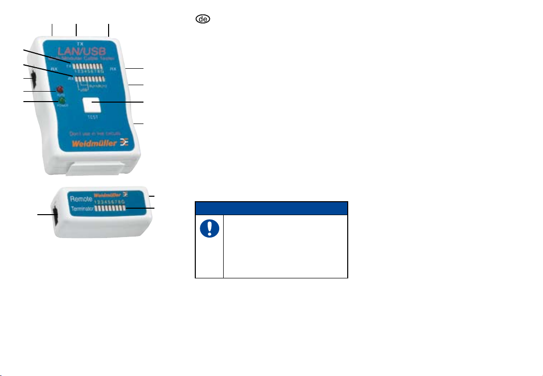
Betriebsarten
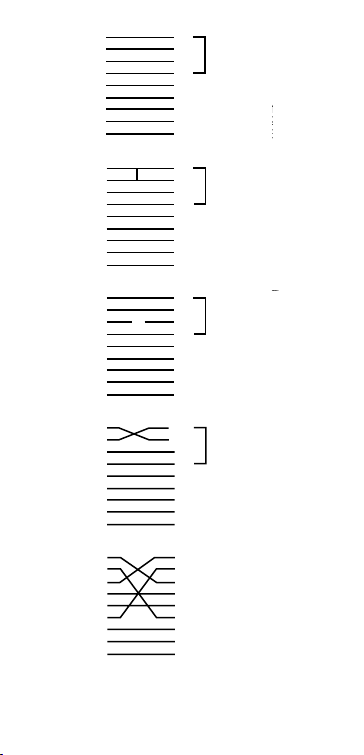
Der LAN/USB-Kabeltester wurde entwickelt, um
die richtige Kabelbelegungs-Konguration auszu-
lesen. Diese Kabel umfassen die USB (A/A),
USB (A/B), BNC 10Base-T, 100Base-TX,
1000Base-TX, Tken Ring, AT&T 258A, Coaxial,
EIA/TIA 568A/568B und RJ11/RJ12 Modular-Ka-
bel. Die Kabel können verbunden werden, wenn
Sie BNC, Coaxial und RCA Modular-Kabel testen
wollen. Wenn Sie abliegend installierte Kabel te-
sten wollen, entweder auf einer Schalttafel oder
einer Wandplatte, benutzen Sie den Remote-Ter-
minator. Der LAN/USB-Kabeltester testet RJ11/
RJ12 Kabel. Bitte benutzen Sie die entspre-
chenden Adapter und befolgen Sie genau die fol-
gende Anweisung.

6
Bedienungsanleitung
Bei Benutzung des Master-Testers verbinden
Sie ein Ende des zu testenden Kabels (RJ45/
USB) mit der „TX“ Markierung und das andere
Ende mit der „RX“ Markierung oder dem Re-
mote-Terminator RJ45/USB-Anschluss.
Schalten Sie den Netzschalter auf “Test“. Im
“step-by-step“ Modus leuchten die LEDs für
Pin 1 auf. Nach Betätigung des „Test“-Schal-
ters werden die LEDs nacheinander aueuch-
ten.
Im „Auto“ Scan-Modus leuchtet die obere Rei-
he der LEDs von Pin 1 bis Pin 8 nacheinan-
der auf.
Das Ergebnis auf dem LED-Display zeigt den
genauen Status des getesteten Kabels an.
Wenn Sie ein falsches LED-Display auslesen,
ist das getestete Kabel kurzgeschlossen, hat
keinen Durchgang, wurde verwechselt oder
wurde falsch angeschlossen.
HINWEIS
Bei schwacher Batterie ist die LED
gedimmt oder sie leuchtet nicht auf,
was zu falschen Testergebnissen
führt.
Remote:
Bei Benutzung des Master-Testers, verbinden
Sie das eine Ende des zu testenden Kabels
mit der “TX“-markierten Buchse und das ande-
re Ende mit dem Eingang des Remote-Termi-
nators. Schalten Sie den Netzschalter auf “Au-
to“ Modus und benutzen Sie das Adapterka-
bel, wenn das Kabel in einer Schalttafel oder
Wandplatte endet.
Die LEDs auf dem Remote-Terminator werden
nacheinander aueuchten, je nachdem wie
der Master-Tester die Kabelbelegung anzeigt.
1
2
3
1
2

7
Correct: 1
2
3
4
5
6
7
8
G
1
2
3
4
5
6
7
8
G
USB A.B TYPE
Open: 1
2
3
4
5
6
7
8
G
1
2
3
4
5
6
7
8
G
USB A.B TYPE OPEN PIN
Short: 1
2
3
4
5
6
7
8
G
1
2
3
4
5
6
7
8
G
USB A.B TYPE SHORT PIN
Crossed: 1
2
3
4
5
6
7
8
G
1
2
3
4
5
6
7
8
G
Reversed: 1
2
3
4
5
6
7
8
G
1
2
3
4
5
6
7
8
G
USB A.B TYPE REVERSED PIN

8
Konformitätserklärung CE
Das Produkt erfüllt die folgenden Richtlinien der
Europäischen Union: 89/336/EWG („Elektroma-
gnetische Verträglichkeit“ und 73/23/EWG (Nie-
derspannungsrichtlinie) wie sie durch die Berich-
tigung 93/68/EWG (CE-Kennzeichnung) vorge-
geben sind.

9
ENGLISH
Device description
LED POWER on/off
LED indicator for auto scan
RX connection, RJ 45
LED Display for RX
LED Display for TX
TX connection, type A USB
TX connection, RJ 45
TX connection, type B USB
RX connection, type A USB
On/Test/Auto switch
„Step-by-Step“ mode button
Battery compartment
Remote RX connection, type A USB
Remote LED display for RX
Remote RX connection, RJ 45
Safety instructions
NOTE
Read these operating instructions
carefully and fully before you operate
this measurement device.
Read the safety notice before begin-
ning any measurements.
1
2
3
4
5
6
7
8
9
10
11
12
13
14
15

10
CAUTION
Before operation always check for
damage to the device. Check also
for indications of heavy contamina-
tion (e.g., grease) or other problems.
Check the testing leads for breaks or
damaged insulation.
Do not use the device if you notice
any irregularities.
Do not use the multimeter while the
battery cover or housing is open.
CAUTION
Electrical interference of electromag-
netic eld in the proximity of the de-
vice can impair the electrical circuit.
Measurement devices are inuenced
by undesired interference in the
measurement circuit. In order to avoid
getting false readings, you should
take the necessary steps and use
caution when measuring near electro-
magnetic interference.
WARNING
If you attempt to measure voltages
which exceed the maximum device
voltage, this can damage the multi-
meter and can put you at risk of an
electric shock. Please pay careful at-
tention to the maximum approved
voltage rating, which is printed on the
front of the device.

11
Recycling in accordance with WEEE
Disposal BtoC
Dear Customer, purchasing our product gives
you the possibility of introducing the device in-
to the recycling process at the end of its lifecycle
free of charge.
The return and recycling of waste elec-
trical and electronics equipment is reg-
ulated by the EU Directive 2002/96 EC
(WEEE). In the Business to Customer
sector, manufacturers of electrical
equipment are obliged as of 13/08/2005 to take
back and recycle free of charge electrical equip-
ment sold after that date. It will then no longer be
allowed to introduce electrical equipment into
“normal” waste streams.
Electrical equipment must then be recycled and
disposed of separately.
All devices that fall under the directive must fea-
ture this logo.
What do you have to do?
Once your device has reached the end of its life-
cycle, simply take it to the Nearest Public Collec-
tion Point for Waste Electrical Equipment. We will
then take care of all recycling and waste dispos-
al measures. You will incur no costs or face any
inconvenience.

12
Maintenance and battery replacement
Maintenance includes periodic cleaning and the
replacement of battery. The outer surface of the
device can be cleaned with a clean dry cloth, in
order to remove oil, grease or dirt. Never use liq-
uid solvents or cleaning agents.
WARNING
In order to avoid an electric shock,
disconnect the testing leads and all
sources of input signals before you
begin replacing the battery. Use an
identical battery type when making a
replacement.
A nine-volt battery is used as the
power source for this device.
Operating modes
The LAN/USB cable tester was developed to
read out the correct cable layout congura-
tion. These cables include USB (A/A), USB (A/
B), BNC 10Base-T, 100Base-TX, 1000Base-
TX, token ring, AT&T 258A, coaxial, EIA/TIA
568A/568B and RJ11/RJ12 modular cables. The
cables can be connected if you wish to test BNC,
coaxial, and RCA modular cables. If you need to
test remotely-installed cables, either on a panel
or wall plate, you can use the remote terminator.
The LAN/USB cable tester can also test RJ11/
RJ12 cable. Please use the correct adapter and
follow the instructions below.

13
Operating instructions
When using the master tester, connect the
end of the cable to be tested (RJ45/USB) with
the „TX“ mark and the other cable end with the
„RX“ mark or with the remote terminator RJ45/
USB connection.
Turn the power switch to „Test“. The LEDs for
pin 1 light up in „step-by-step“ mode. After op-
erating the „Test“ switch, the LEDs illuminate
one after the other.
In the „Auto“ scan mode, the upper row of
LEDs light, one after the other from pin 1 to
pin 8.
The results on the LED show the exact status
of the cable being tested. If a false LED se-
quence is displayed then the tested cable has
a short circuit, a break, false wiring or a false
connection.
NOTE
When the battery is weak, the LED
is faint or not lit up. This can lead to
false test results.
Remote:
When using the master tester, connect the
end of the cable to be tested with the socket
marked „TX“. Connect the other end of the ca-
ble in the input on the remote terminator. Set
the power switch to the „Auto“ mode. If the ca-
ble terminates in a panel or wall plate then
make use of the adapter cable.
The LEDs on the remote terminator light up
one after the other, depending on the cable
layout detected by the master tester.
1
2
3
1
2

14
Correct: 1
2
3
4
5
6
7
8
G
1
2
3
4
5
6
7
8
G
USB A.B TYPE
Open: 1
2
3
4
5
6
7
8
G
1
2
3
4
5
6
7
8
G
USB A.B TYPE OPEN PIN
Short: 1
2
3
4
5
6
7
8
G
1
2
3
4
5
6
7
8
G
USB A.B TYPE SHORT PIN
Crossed: 1
2
3
4
5
6
7
8
G
1
2
3
4
5
6
7
8
G
Reversed: 1
2
3
4
5
6
7
8
G
1
2
3
4
5
6
7
8
G
USB A.B TYPE REVERSED PIN

15
Declaration of conformity CE
This product fulls the following European Union
guidelines: 89/336/EWG (Electromagnetic Com-
patibility) and 73/23/EWG (Low Voltage Direc-
tive) as detailed in the amendment 93/68/EWG
(CE Labels).

16
FRANCAIS
Description de l‘appareil
DEL POWER marche/arrêt
Témoin DEL scan auto
Prise RX en RJ45
Afcheur DEL pour RX
Afcheur DEL pour TX
Prise TX, en USB type A
Prise TX, en RJ45
Prise TX, en USB type B
Prise RX, en USB type A
Commutateur Marche/Test/Auto
Bouton-poussoir de mode „pas à pas“
Compartiment pile
Prise RX déporté, en USB type A
Afcheur DEL déporté pour RX
Prise RX déporté, en RJ45
Consignes de sécurité
REMARQUE
Veuillez lire attentivement et complè-
tement ce mode d‘emploi avant de
manipuler l‘appareil.
Avant de commencer à mesurer,
veuillez lire les consignes de sécu-
rité.
1
2
3
4
5
6
7
8
9
10
11
12
13
14
15

17
ATTENTION
Veuillez toujours vérier avant de me-
surer que l‘appareil n‘est pas endom-
magé, ne présente pas de salissures
(par ex. de graisses) trop importan-
tes ou ne soit pas défectueux d‘une
manière ou d‘une autre. Contrôlez les
cordons de test en vue de toute rup-
ture ou défaut d‘isolation. S‘il quelque
chose ne vous semble pas normal,
n‘utilisez pas l‘appareil.
Ne pas utiliser le multimètre si le boî-
tier est ouvert ou si le capot de la pi-
le est ouvert.
ATTENTION
Les bruits de fond d‘origine électrique
ou les champs électromagnétiques à
proximité de l‘appareil peuvent nuire
au circuit électrique. Les appareils de
mesure réagissent également aux per-
turbations indésirables dans le circuit
de mesure. An d‘éviter tout résultat
incohérent, les utilisateurs doivent de
ce fait procéder soigneusement lors
des mesures à proximité de perturba-
tions électromagnétiques, et prendre
des dispositions correspondantes.
ATTENTION
La mesure de tensions dépassant
la tension maximum autorisée peut
conduire à endommager l‘appareil de
mesure et exposer l‘utilisateur à un
risque de choc électrique. Observez
donc toujours la tension la plus éle-
vée admissible, imprimée sur la face
avant de l‘appareil.

18
Recyclage selon DEEE
Elimination des déchets professionnels
her client, en achetant notre produit, vous pour-
rez après sa n de cycle de vie porter gratuite-
ment l‘appareil au processus de recyclage.
La reprise et le recyclage des équipe-
ments électriques est réglementée par
la DEEE (directive UE 2002/96/UE).
Dans le domaine grand public, les fa-
bricants d‘équipements électriques ont
l‘obligation à compter du 13/8/2005 de reprendre
et de recycler gratuitement les équipements élec-
triques et électroniques vendus après cette date.
Les équipements électriques ne devront alors
plus être portés dans les circuits de déchets «ha-
bituels». Les équipements électriques doivent
être recyclés et éliminés séparément.
Tous les équipements concernés par cette direc-
tive sont identiés par ce symbole.
Que devez-vous faire ?
Lorsque votre appareil aura atteint sa n de vie,
portez-le simplement au point de collecte pu-
blic pour anciens équipements électriques le plus
proche. Nous prendrons alors toutes les mesu-
res qui s‘imposent pour le recyclage et l‘élimina-
tion. Vous n‘aurez aucun frais supplémentaire ni
inconvénients à votre charge.

19
Entretien + remplacement de la pile
L‘entretien consiste en un nettoyage régulier ain-
si qu‘au remplacement de la pile. L‘extérieur de
l‘appareil se nettoie à l‘aide d‘un chiffon propre et
sec, pour enlever toute trace d‘huile, de graisse
ou de saleté. N‘utilisez jamais de solvant liquide
ou d‘agent de nettoyage.
ATTENTION
An d‘éviter tout choc électrique, dé-
connectez aussi bien les cordons de
test que toute source de signal d‘en-
trée avant de remplacer la pile. Rem-
placez la pile par une autre du mê-
me type.
La source d‘énergie de cet appareil
de mesure est une pile 9 Volt.
Modes de fonctionnement
Le testeur de câble RLE/USB a été conçu pour
la lecture de la bonne conguration de brocha-
ge de câble. Il s‘agit des câbles USB (A/A), USB
(A/B), BNC 10Base-T, 100Base-TX, 1000Ba-
se-TX, Token Ring, AT&T 258A, coaxial, EIA/
TIA 568A/568B et RJ11/RJ12 modulaires. Vous
pouvez relier ces câbles entre eux si vous vou-
lez tester des câbles modulaires BNC, coaxiaux
et RCA. Si vous voulez tester des câbles instal-
lés à distance, soit sur un tableau électrique soit
sur un panneau mural, utilisez le terminateur dis-
tant (Remote). Le testeur de câble RLE/USB
peut tester les câbles RJ11/RJ12. Veuillez utiliser
l‘adaptateur correspondant et suivez scrupuleu-
sement les instructions suivantes.

20
Mode d‘emploi
Pour utiliser le testeur maître, reliez une ex-
trémité du câble à tester (RJ45/USB) sur le
repère „TX“ et l‘autre extrémité sur le repè-
re „RX“ ou sur la prise RJ45/USB du termina-
teur distant.
Basculez l‘interrupteur secteur sur „Test“. En
mode „pas à pas“, les DEL de la broche 1 s‘al-
lument. Après avoir actionné le bouton „Test“,
les DEL s‘allumeront l‘une après l‘autre.
En mode d‘analyse „Auto“, la rangée supé-
rieure de diodes s‘allume successivement de
la broche 1 à la broche 8.
Le résultat sur l‘afcheur à DEL indique l‘état
exact du câble testé. Si vous lisez un afcha-
ge DEL erroné, le câble testé est en court-cir-
cuit, n‘a pas de continuité, a été intervertit ou
mal connecté.
REMARQUE
En cas de pile faible, la DEL est
diminuée ou ne s‘allume pas, ce qui
peut conduire à de mauvais résultats
de test.
Terminateur „Remote“ :
Pour utiliser le testeur maître, reliez une des
extrémités du câble à tester sur la prise femel-
le repérée „TX“ et l‘autre extrémité sur l‘entrée
du terminateur distant. Basculez l‘interrup-
teur secteur en mode „Auto“ et utilisez le câble
adaptateur si le câble est relié sur un tableau
électrique ou sur un panneau mural.
Les diodes luminescente du terminateur dis-
tant s‘allument successivement, selon la ma-
nière dont le testeur maître indique le brocha-
ge du câble.
1
2
3
1
2
This manual suits for next models
1
Table of contents
Languages: