Simplay Labs SL-889 User manual

SL-889 HDMI 2.1 Cat-3 Cable EMI Tester
User Guide
Simplay-UG-SL889-1.1
Aug 2020
SL-889 HDMI 2.1 Cat-3 Cable EMI Tester
User Guide
2 © 2019-2020 Simplay Labs, LLC., Simplay-UG-SL889-1.1
All rights reserved. CONFIDENTIAL
Contents
1. Overview........................................................................................................................................................................4
SL-889 Hardware ...................................................................................................................................................4
1.1.1. Signal Path.......................................................................................................................................................5
SL-889 Controls, Indicators, and Interface Connectors ..........................................................................................6
SL-889 Test Modes .................................................................................................................................................6
1.3.1. Standard Test Mode ........................................................................................................................................6
1.3.2. Devices under Test ..........................................................................................................................................8
HDMI 2.1 Video Resolution Support.......................................................................................................................8
Inside the Box .........................................................................................................................................................8
1.5.1. 12V Power Supply ...........................................................................................................................................9
1.5.2. 2M Golden Test HDMI Cat-3 Cable .................................................................................................................9
2. The SL-889 in Standard Test Mode..............................................................................................................................10
Calibrated HDMI 2.1 Tx Output Notes:.................................................................................................................10
Setting up Connections –Pre-Test Operation ......................................................................................................11
Setting up Connections –Normal Operation .......................................................................................................12
Operation - Detailed.............................................................................................................................................12
Operation –Quick Start........................................................................................................................................14
Chamber Set Up....................................................................................................................................................15
2.6.1. CISPR Chamber Set Up –Cable Placement....................................................................................................15
2.6.2. HDMI Forum Recommended Chamber Set Up –Cable Placement...............................................................15
3. RF Scans and EMI Chamber measurements with the SL-889 ......................................................................................16
HDMI 2.1 EMI Measurement................................................................................................................................16
3.1.1. EMI Chamber RF Emission Scans...................................................................................................................16
EMI Limits and Testing..........................................................................................................................................17
3.2.1. CISPR 32 EMI Testing Standards....................................................................................................................17
3.2.2. HDMI Forum Cat-3 Cable EMI Testing Guidelines .........................................................................................17
Appendix A. Internal Firmware Upgrade ......................................................................................................................18
A.1. Update Firmware/Scripts/Test Images.................................................................................................................19
References ..........................................................................................................................................................................24
Revision History ..................................................................................................................................................................25

SL-889 HDMI 2.1 Cat-3 Cable EMI Tester
User Guide
Simplay-UG-SL889-1.1 © 2019-2020 Simplay Labs, LLC., 3
All rights reserved. CONFIDENTIAL
Figures
Figure 1.1. SL-889 − Top View...............................................................................................................................................4
Figure 1.2. SL-889 − Front Panel View ..................................................................................................................................4
Figure 1.3. SL-889 − Rear Panel View ...................................................................................................................................5
Figure 1.4. SL-889 –Signal Path............................................................................................................................................5
Figure 1.5. Locating SL-889 Components − Top View...........................................................................................................6
Figure 1.6. LCD Display Screen Main Window ......................................................................................................................7
Figure 1.7. 12V Power Supply...............................................................................................................................................9
Figure 1.8. 2M Golden Cat-3 HDMI 2.1 Cable.......................................................................................................................9
Figure 2.1. Pre-Test: Connecting the DUT cable with optional monitor output.................................................................11
Figure 2.2. Test: Connecting the DUT cable in Normal Operation .....................................................................................12
Figure 2.3. SL-889 Operation: Boot Down Counter ............................................................................................................12
Figure 2.4. SL-889 Operation: C0 Resolution, V1.00 Firmware, No HDMI Cable Attached ...............................................13
Figure 2.5. SL-889 Operation: Selector ..............................................................................................................................13
Figure 2.6. SL-889 Operation: C4 Resolution, No Cable Attached .....................................................................................13
Figure 2.7. SL-889 Operation: C4 Resolution, TMDS 185 MHz link, HDMI Cable Attached ...............................................14
Figure 2.8. SL-889 Operation: Optional Monitor Output...................................................................................................14
Figure 2.9. CISPR recommended DUT cable placement inside chamber............................................................................15
Figure 2.10. HDMI Forum recommended DUT cable placement inside chamber ..............................................................15
Figure 3.1. 30MHz-1000MHz Scan......................................................................................................................................16
Figure 3.2. 1000MHz-6000MHz Scan..................................................................................................................................16
Figure 3.3. HDMI Forum recommended DUT cable placement inside chamber ................................................................17
Figure A.1. SimplayLabs SL-889 Web Support Page ...........................................................................................................18
Figure A.2. SL-889 Firmware Version Display .....................................................................................................................18
Figure A.3. SL-889 Firmware update via network port.......................................................................................................19

SL-889 HDMI 2.1 Cat-3 Cable EMI Tester
User Guide
4 © 2019-2020 Simplay Labs, LLC., Simplay-UG-SL889-1.1
All rights reserved. CONFIDENTIAL
1. Overview
The SL-889 HDMI 2.1 Cat-3 Cable EMI Tester is designed for radiated emissions testing of HDMI 2.1 Ultra High Speed
cables and is compliant to the latest High Definition Multimedia Interface (HDMI®) 2.1 specifications.
This User Guide provides details on how to setup and test cables for radiated emissions for compliance in a EMI
chamber to HDMI 2.1 specifications.
For the latest updates to documentation or software updates, see online at:
https://www.simplaylabs.com/ProductsServices/Products/HDMI/ .
SL-889 Hardware
Figure 1.1, Figure 1.2, and Figure 1.3 show the top view, the front panel view, and the rear panel view of the SL-889,
respectively.
Figure 1.1. SL-889 −Top View
Figure 1.2. SL-889 −Front Panel View

SL-889 HDMI 2.1 Cat-3 Cable EMI Tester
User Guide
Simplay-UG-SL889-1.1 © 2019-2020 Simplay Labs, LLC., 5
All rights reserved. CONFIDENTIAL
Figure 1.3. SL-889 −Rear Panel View
1.1.1. Signal Path
Figure 1.3 shows the internal and external signal path of the SL-889. An internal Video Generator generates an ITU-R
BT-1729 test pattern which is fed to an HDMI transmitter. When an external HDMI cable DUT is connected, the Tx will
begin transmitting a HDMI 2.1 Video/Audio data stream to the built-in HDMI receiver. At this point the Test Equipment
can be used inside an RF chamber, and radiated emissions scans may be taken. An optional LCD monitor can be used
during Pre-Scan operations to visually verify the signal has been successfully received across the DUT cable.
Figure 1.4. SL-889 –Signal Path

SL-889 HDMI 2.1 Cat-3 Cable EMI Tester
User Guide
6 © 2019-2020 Simplay Labs, LLC., Simplay-UG-SL889-1.1
All rights reserved. CONFIDENTIAL
SL-889 Controls, Indicators, and Interface Connectors
Figure 1.5 shows the location of the SL-889 enclosure features: input and output ports, power and ethernet, LCD
display, and resolution select rotary switch.
Figure 1.5. Locating SL-889 Components −Top View
Item
Label
Description
1
Network
RJ45 Ethernet Port.
2
+12 V DC
DC power receptacle, 12 V 2 A.
3
HDMI OUT1
HDMI TX0 output Port. For Cable DUT Transmit.
4
HDMI OUT2
HDMI TX1 output Port. For Optional Display Monitor output.
5
HDMI IN1
HDMI RX0 input Port. For Cable DUT Receive.
6
Selector
Resolution Select Rotary Switch
7
LCD Display
Alphanumeric LCD display that shows resolution selected and connection status.
SL-889 Test Modes
The SL-889 is designed to offer the following distinct mode of operation:
•Standard Test Mode, see Section 1.3.1.
1.3.1. Standard Test Mode
In its standard test configuration, the SL-889 offers audio and video generation and reception features to enable
radiated emissions compliance testing to HDMI 2.1 specifications.
1.3.1.1. Available Standard Tests
The SL-889 is ready for use in standard test mode immediately upon delivery. These are the operations that are done in
standard test mode:
LCD Alphanumeric
Display
1
2
3 4 5
6
7
SL-889 HDMI 2.1 Cat-3 Cable EMI Tester
User Guide
Simplay-UG-SL889-1.1 © 2019-2020 Simplay Labs, LLC., 7
All rights reserved. CONFIDENTIAL
1. Generate a calibrated HDMI 2.1 output signal using HDMI OUT1 port
2. Receive and Analyze a HDMI 2.1 input signal using HDMI IN1 port
3. Generate an optional display monitor output signal using HDMI OUT2 port
For details of the above operations, refer to Section 2.
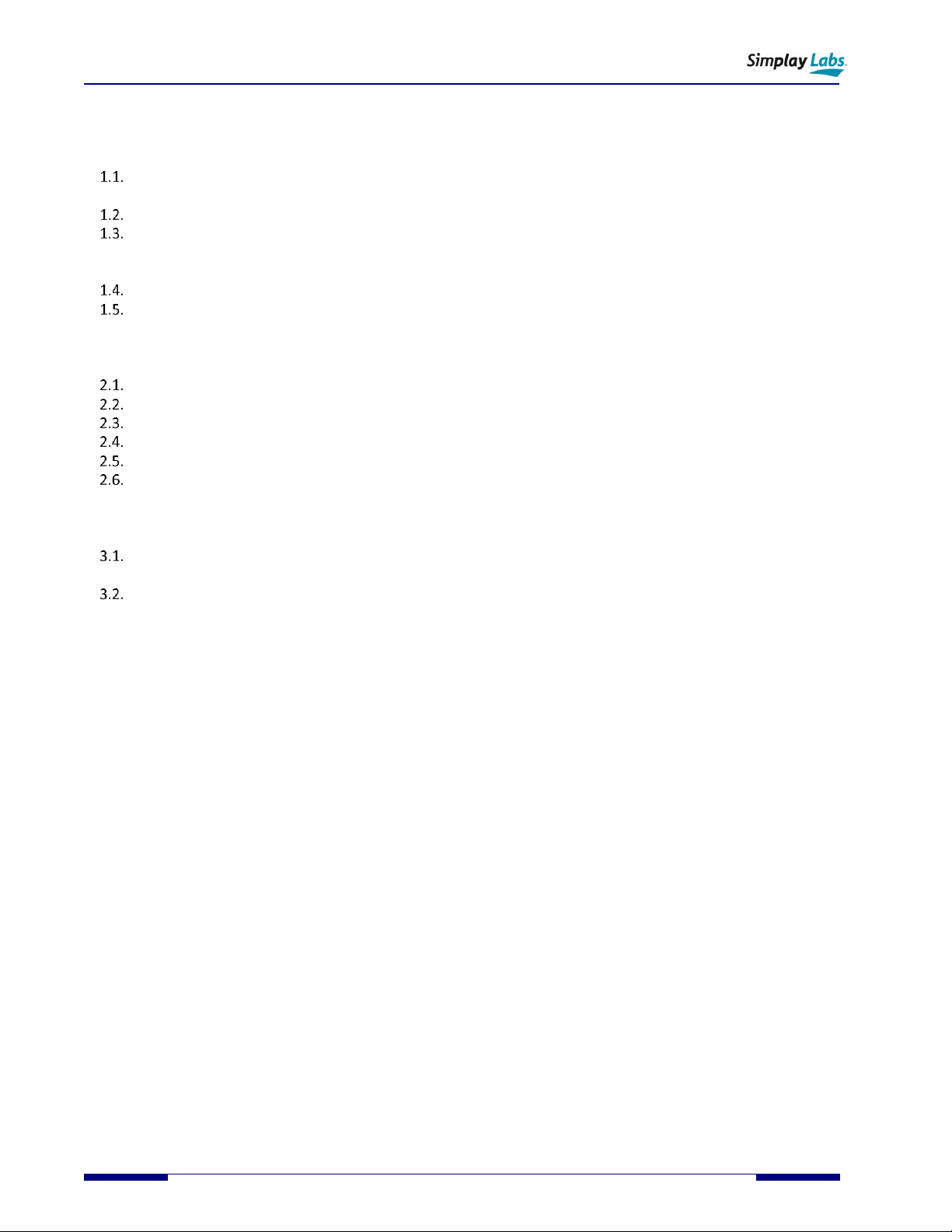
1.3.1.2. The SL-889 LCD Display Screen in Standard Test Mode
Figure 1.6 shows the LCD display screen of the SL-889 in standard test mode under default factory configuration.
Figure 1.6. LCD Display Screen Main Window

SL-889 HDMI 2.1 Cat-3 Cable EMI Tester
User Guide
8 © 2019-2020 Simplay Labs, LLC., Simplay-UG-SL889-1.1
All rights reserved. CONFIDENTIAL
1.3.2. Devices under Test
Standard test operations are available for:
•HDMI 2.1 Cat-3 Cables
HDMI 2.1 Video Resolution Support
The SL-889 includes support for TMDS and FRL signalling:
•6 TMDS Freqencies supported with 4 Video Resolutions
•2 FRL Frequencies with 2160p60 Video Resolution
Value
Description
C0
720x480p60 (16:9) RGB 8-bit 27 MHz -
C1
720x480p60 (16:9) RGB 8-bit 27 MHz
C2
720x480p60 (16:9) RGB 12-bit -40.5 MHz
C3
1920x1080p60 RGB 8-bit 148.5 MHz
C4
1920x1080p60 RGB 10-bit 185 MHz
C5
3840x2160p24 RGB 8-bit 297 MHz
C6
3840x2160p60 RGB 8-bit 594 MHz
C7
3840x2160p60 FRL 6 GHz 4 Lane FRL
C8
3840x2160p60 FRL 12GHz 4 Lane FRL + eARC
C9-C15
3840x2160p60 FRL 6 GHz 4 Lane FRL (Subject to change, reserved for future use)
Note: Resolutions in bold are required resolutions for HDMI 2.1 radiated emissions testing.
Inside the Box
The SL-889 delivery includes the following items:
•SL-889 HDMI 2.1 Cat-3 Cable EMI Test Tool
•SL-889-PS 12V power supply
•SL-889-GC 2M HDMI 2.1 Cat-3 Golden Test Cable
•Quick Start Guide
•Calibration Packet
SL-889 HDMI 2.1 Cat-3 Cable EMI Tester
User Guide
Simplay-UG-SL889-1.1 © 2019-2020 Simplay Labs, LLC., 9
All rights reserved. CONFIDENTIAL
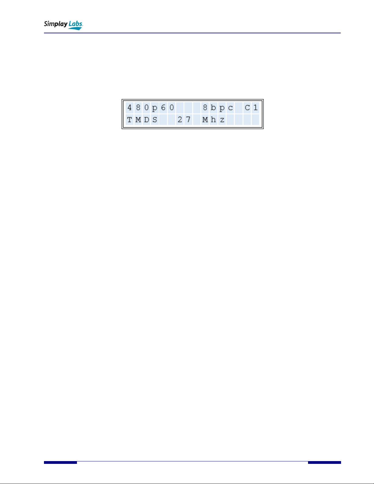
1.5.1. 12V Power Supply
The included 12V power supply has been chosen for proper operation with the SL-889. It has been modified with the
addition of a ferrite filter for lower noise operation. Please do not substitute another supply as the results of EMI scans
cannot be guaranteed.
Figure 1.7. 12V Power Supply
1.5.2. 2M Golden Test HDMI Cat-3 Cable
The included 2M cable has been developed for specific use with the SL-889. It has been shown to have superior RF
suppression. It should be kept as a test reference cable and can be used to calibrate your SL-889 to different RF
chambers.
Figure 1.8. 2M Golden Cat-3 HDMI 2.1 Cable

SL-889 HDMI 2.1 Cat-3 Cable EMI Tester
User Guide
10 © 2019-2020 Simplay Labs, LLC., Simplay-UG-SL889-1.1
All rights reserved. CONFIDENTIAL
2. The SL-889 in Standard Test Mode
In its standard test configuration, the SL-889 offers audio and video test features to enable radiated emissions
compliance testing to HDMI 2.1 specifications.
These are the operations that are available in the standard test mode:
1. Generate a calibrated HDMI 2.1 signal output using the HDMI OUT1 port
2. Receive a HDMI 2.1 signal using the HDMI IN1 port
Calibrated HDMI 2.1 Tx Output Notes:
The SL-889 generates fixed stimulus to an HDMI 2.1 Category 3 Cable so the DUT cable’s EMC
Emission performance can be measured.
The SL-889 does not go through HDMI 2.1 FRL Link Training, and does not adjust the TX signal in
response to the RX’s measured error rate.
The documentation shipped with each SL-889 contains waveforms captured while it was sending
TMDS data at 2.97 GHz and FRL data at 12.0 GBPS.
A waveform exhibiting a Rising/Falling/Rising pattern (or a Falling/Rising/Falling pattern), with the
time between the first and last edges at a minimum, represents 2 bit times.
The included 12.0 GHz waveform was captured at 200 Picoseconds (ps) per division, with each
division internally subdivided by four tick marks.
Each 1/5th of a division is 40 ps.
A 12.5 GBPS signal would result in a bit time of 80 ps.
In the faster waveform the time between the first and last edges of the Rising/Falling/Rising
pattern is slightly more than 4 tick marks (160 ps).
One bit time is half the total time, or slightly more than 80 pS.
SL-889 HDMI 2.1 Cat-3 Cable EMI Tester
User Guide
Simplay-UG-SL889-1.1 © 2019-2020 Simplay Labs, LLC., 11
All rights reserved. CONFIDENTIAL
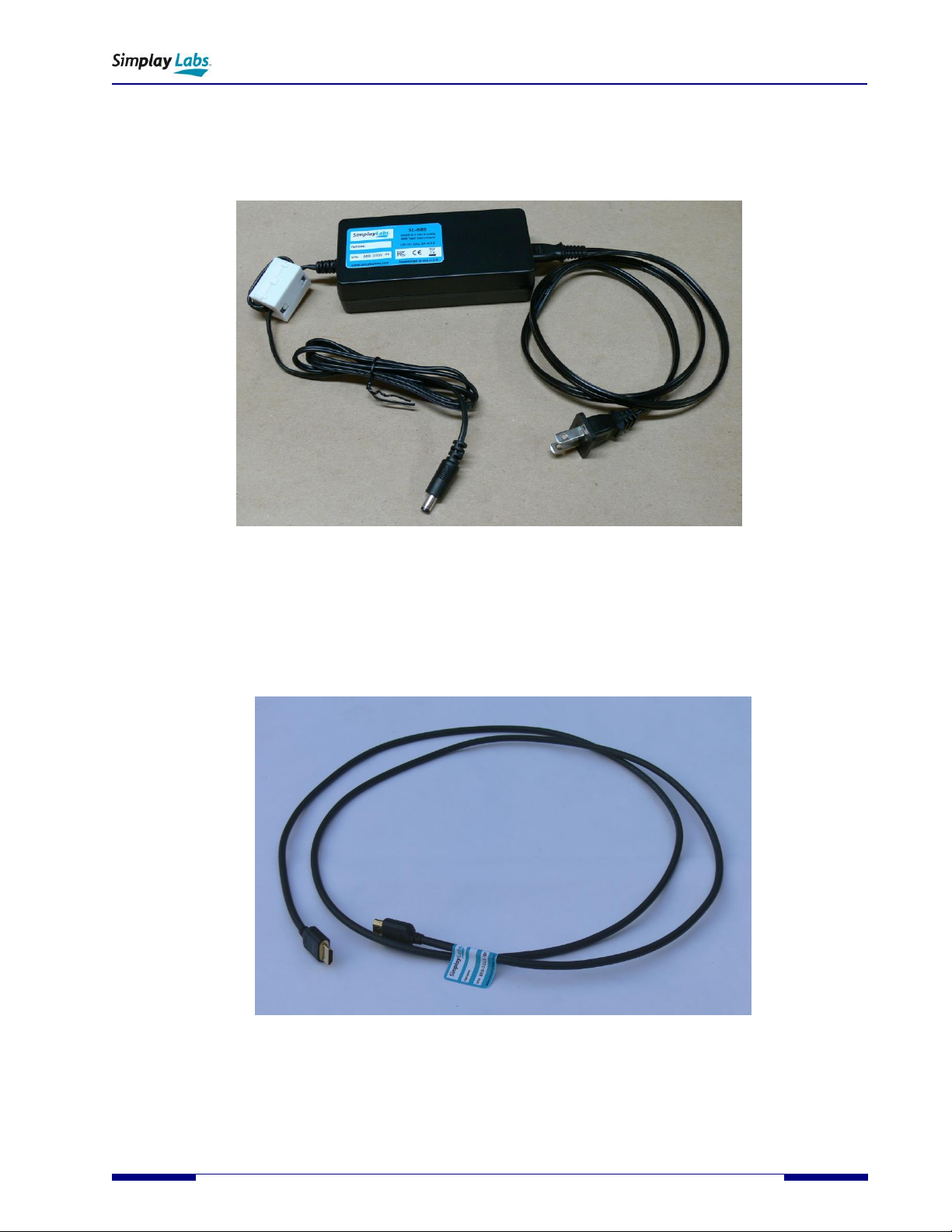
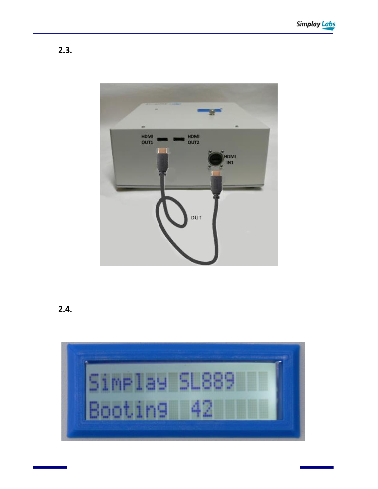
Setting up Connections –Pre-Test Operation
Connecting the DUT cable and optional HDMI monitor cable to the SL-889:
•When performing EMI RF scans, the DUT cable should be connected from HDMI OUT1 to HDMI IN1 as shown in
Figure 2.1.
•When pre-testing, an optional 4K TMDS monitor can be connected to visualize the ITU BT1729 test pattern as
shown in Figure 2.1.Note: As the test is intended to measure only the radiated emissions of the DUT cable, the
cable from HDMI OUT2 should be disconnected from the SL-889, and the 4K Monitor should be unplugged from AC
power prior to making any EMI measurement scans.
Figure 2.1. Pre-Test: Connecting the DUT cable with optional monitor output
SL-889 HDMI 2.1 Cat-3 Cable EMI Tester
User Guide
12 © 2019-2020 Simplay Labs, LLC., Simplay-UG-SL889-1.1
All rights reserved. CONFIDENTIAL
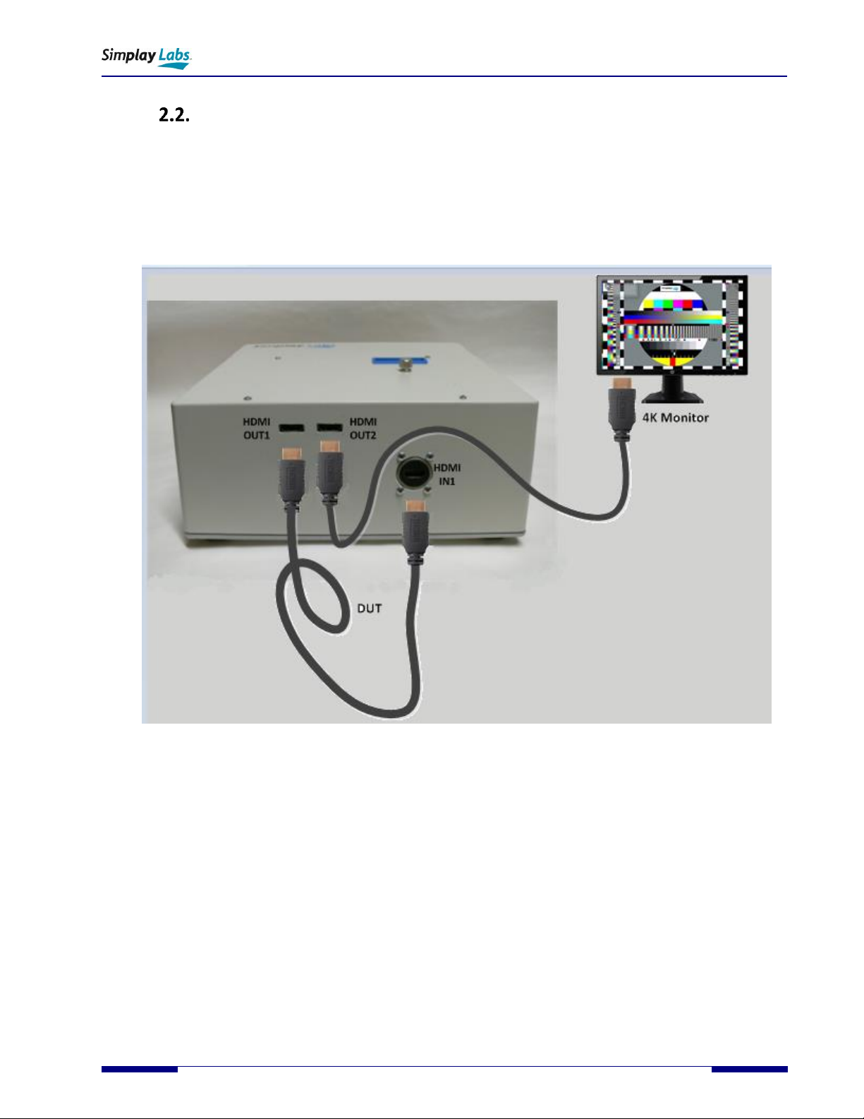
Setting up Connections –Normal Operation
Connecting the DUT cable to the SL-889:
•When performing EMI RF scans, the DUT cable should be connected from HDMI OUT1 to HDMI IN1 as shown
in Figure 2.2Figure 2.2. Test: Connecting the DUT cable in Normal Operation.
Figure 2.2. Test: Connecting the DUT cable in Normal Operation
Operation - Detailed
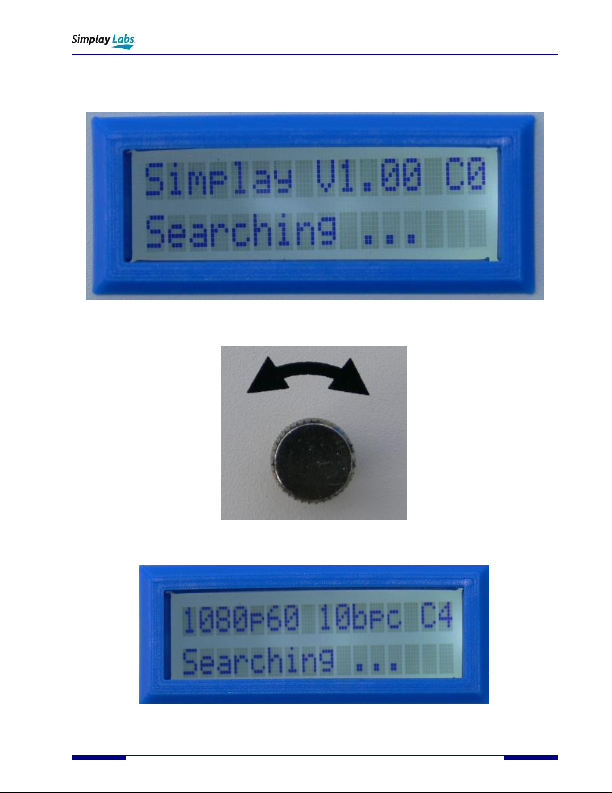
The SL-889 operation is as follows:
1. Plug in the supplied 12V DC power supply into the unit. The LCD screen will light and the internal fan may be
heard. The LCD will display a boot message, along with a down counter.
Figure 2.3. SL-889 Operation: Boot Down Counter
SL-889 HDMI 2.1 Cat-3 Cable EMI Tester
User Guide
Simplay-UG-SL889-1.1 © 2019-2020 Simplay Labs, LLC., 13
All rights reserved. CONFIDENTIAL
2. After approximately 45 seconds the boot process completes. The first line of the LCD will display a message
corresponding to the last known switch position (C0-C15). The second line will display “Searching …” if an HDMI
cable has not yet been connected from HDMI OUT1 to HDMI IN1.
Figure 2.4. SL-889 Operation: C0 Resolution, V1.00 Firmware, No HDMI Cable Attached
3. Rotate the knob to select the resolution to be tested.
Figure 2.5. SL-889 Operation: Selector
4. The LCD will display the selected resolution.
Figure 2.6. SL-889 Operation: C4 Resolution, No Cable Attached

SL-889 HDMI 2.1 Cat-3 Cable EMI Tester
User Guide
14 © 2019-2020 Simplay Labs, LLC., Simplay-UG-SL889-1.1
All rights reserved. CONFIDENTIAL
5. Attach an HDMI cable from HDMI OUT1 to HDMI IN1. The second line of the LCD will transition from “Searching…”
to an informational message (ex: “TMDS 185 MHz”) when a link has been successfully connected. The unit is now
ready for EMI scans to be taken.
Figure 2.7. SL-889 Operation: C4 Resolution, TMDS 185 MHz link, HDMI Cable Attached
6. Attach an optional HDMI monitor to HDMI OUT2 to display the ITU BT1729 test pattern.
Figure 2.8. SL-889 Operation: Optional Monitor Output
Operation –Quick Start
Pre-test Setup:
1. Attach the +12V power supply to the unit. You will hear the internal fans if you listen closely.
2. The LCD lights up and displays a boot down count screen as it powers up.
3. After the internal boot counts completes, the LCD will change to show the last resolution selected.
4. The selector knob chooses between 16 different resolutions.
5. Rotate the selector knob to choose the desired resolution.
6. The LCD screen shows “C0” – “C15” in the upper right.
7. Attach an optional 4K monitor to the HDMI OUT2 output connector.
8. Attach a DUT cable between the HDMI OUT1 output and HDMI IN1 input connectors.
9. The ITU-R BT.1729. (2005). Common 16:9 or 4:3 aspect ratio digital television reference test pattern should
appear on the monitor.
Note: Monitor output is only available if a DUT cable is attached. (See Signal Path diagram)
Taking Scans:
10. Disconnect the Monitor from the SL-889 HDMI OUT2 output, and unplug it.

SL-889 HDMI 2.1 Cat-3 Cable EMI Tester
User Guide
Simplay-UG-SL889-1.1 © 2019-2020 Simplay Labs, LLC., 15
All rights reserved. CONFIDENTIAL
11. Take Scans
Chamber Set Up
This section provides only a cursory descrition of chamber set up. It is assumed that most EMI testing will take place in
a chamber with the instrument placed on top of a suitable table that is capable of 360 degree rotation. Furthermore,
the antenna will be at a fixed distance from the front of the table.
2.6.1. CISPR Chamber Set Up –Cable Placement
For CISPR compliance it is assumed that the SL-889 would be pushed to the front of the table facing the antenna with
the DUT cable draped down the front as shown in (Figure 2.9. CISPR recommended DUT cable placement inside
chamber), and tied in a loose bow to prevent it from hitting the floor. Consult the CISPR specification for details.
Figure 2.9. CISPR recommended DUT cable placement inside chamber
2.6.2. HDMI Forum Recommended Chamber Set Up –Cable Placement
For HDMI Forum compliance it is assumed that the SL-889 would be pushed to the back of the table facing the antenna
with the DUT cable placed horizontally on the table down the front as shown in (Figure 2.10). Consult the HDMI Forum
Guidelines for details
Figure 2.10. HDMI Forum recommended DUT cable placement inside chamber
SL-889 HDMI 2.1 Cat-3 Cable EMI Tester
User Guide
16 © 2019-2020 Simplay Labs, LLC., Simplay-UG-SL889-1.1
All rights reserved. CONFIDENTIAL
3. RF Scans and EMI Chamber measurements with the SL-889
HDMI 2.1 EMI Measurement
The SL-889 provides a complete transmit and receive solution of a compliant HDMI 2.1 signal output in a low noise
shielded enclosure. It can be used to measure the radiated emission levels of HDMI cables by taking RF level scans in a
calibrated EMI chamber.
3.1.1. EMI Chamber RF Emission Scans
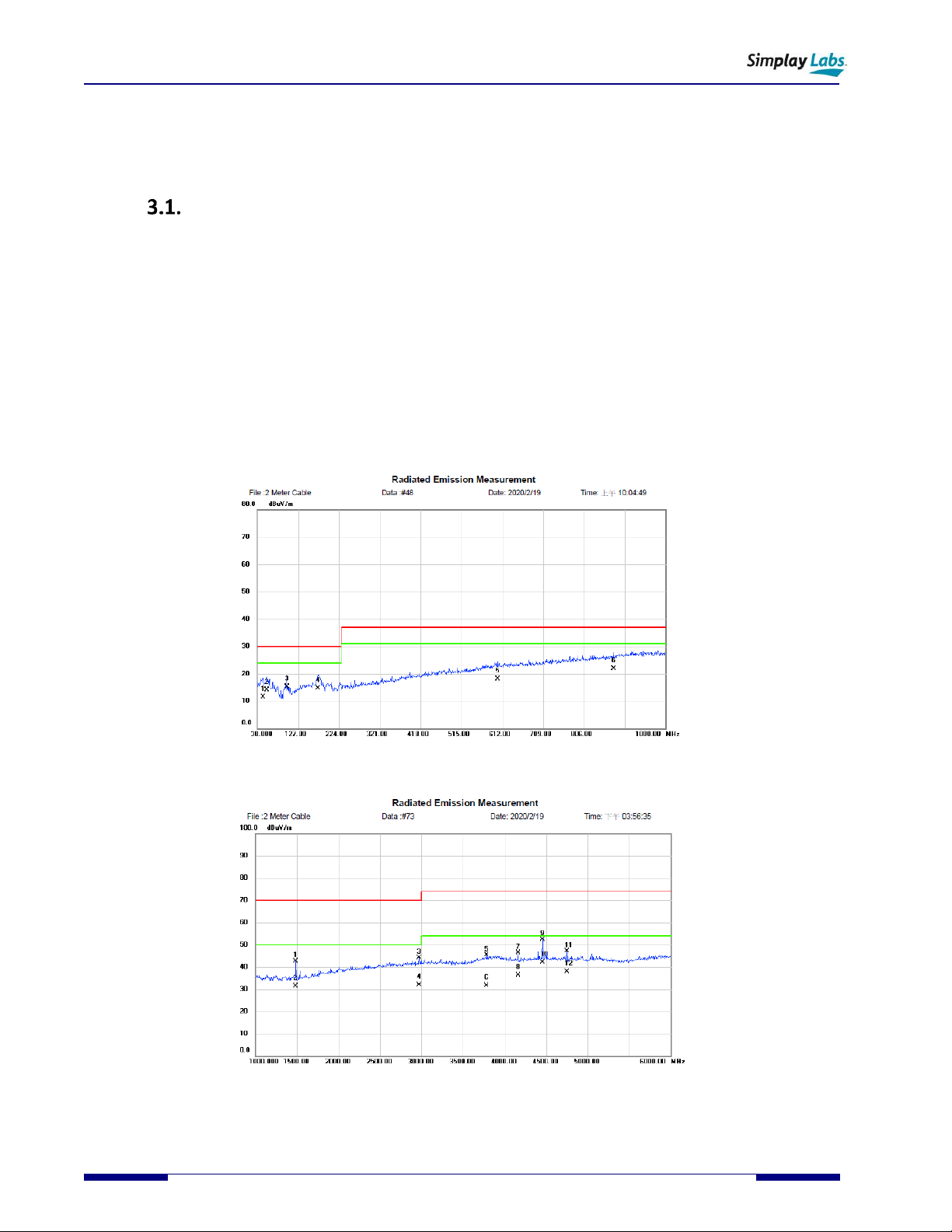
Generally speaking RF emission scans for multimedia equipment are usually taken in 2 distinct frequency groups: 30
MHz-1 GHz see Figure 3.1., and 1GHz-6GHz see Figure 3.2. This is usually done because antenna, amplifier and chamber
requirements make this a convenient split and most standards recognize these splits. Additionally, most EMI test
specifications require that the DUT (e.g.Cable) be located at a fixed distance from the antenna (usually 3m or 10m), and
that horizontal and vertical scans be taken while simultaneously rotating the DUT 360 degrees while raising and
lowering the antenna to discover the position of maximum radiated energy.
Figure 3.1. 30MHz-1000MHz Scan
Figure 3.2. 1000MHz-6000MHz Scan

SL-889 HDMI 2.1 Cat-3 Cable EMI Tester
User Guide
Simplay-UG-SL889-1.1 © 2019-2020 Simplay Labs, LLC., 17
All rights reserved. CONFIDENTIAL
EMI Limits and Testing
EMI or electromagnetic interference is the measure of the radiated RF energy that a device puts out. The SL-889 makes
measuring the amount of RF energy an HDMI cable emits easy, by providing a calibrated HDMI signal. Maximum
allowable EMI limits vary from country to country, and this tool was developed to help standardize the rf emission
measurement of cables regardless of country standard.
3.2.1. CISPR 32 EMI Testing Standards
EMI testing per the HDMI Forum Guidelines generally follows the International Electrotechnical Commision CISPR
32:2015 standard. The comission and standard can be found at https://www.iec.ch/ . Please refer to the standard for
test setup, chamber set up, emission levels, test pattern, etc.
3.2.2. HDMI Forum Cat-3 Cable EMI Testing Guidelines
The HDMI Forum has an interest in making sure cables that transmit HDMI signals comply with EMI limits of individual
countries. And because HDMI is a worldwide standard, it made sense to establish a set of EMI Guidelines for Cat-3
cables that could be adopted worldwide. For guidance to performing the radiated emissions checking per the HDMI
Forum Guidelines, please refer to the following HDMI Forum Policy: “Category 3 Cable Assembly EMI Testing
Policy and Process, dated 5/7/2020” (www.hdmiforum.org)
The Forum Policy covers both technical requirements (cable placement, resolution(s), passing criteria, etc), as well as
process requirements (number of cables tested, etc.).
Figure 3.3. HDMI Forum recommended DUT cable placement inside chamber
SL-889 HDMI 2.1 Cat-3 Cable EMI Tester
User Guide
18 © 2019-2020 Simplay Labs, LLC., Simplay-UG-SL889-1.1
All rights reserved. CONFIDENTIAL
Appendix A. Internal Firmware Upgrade
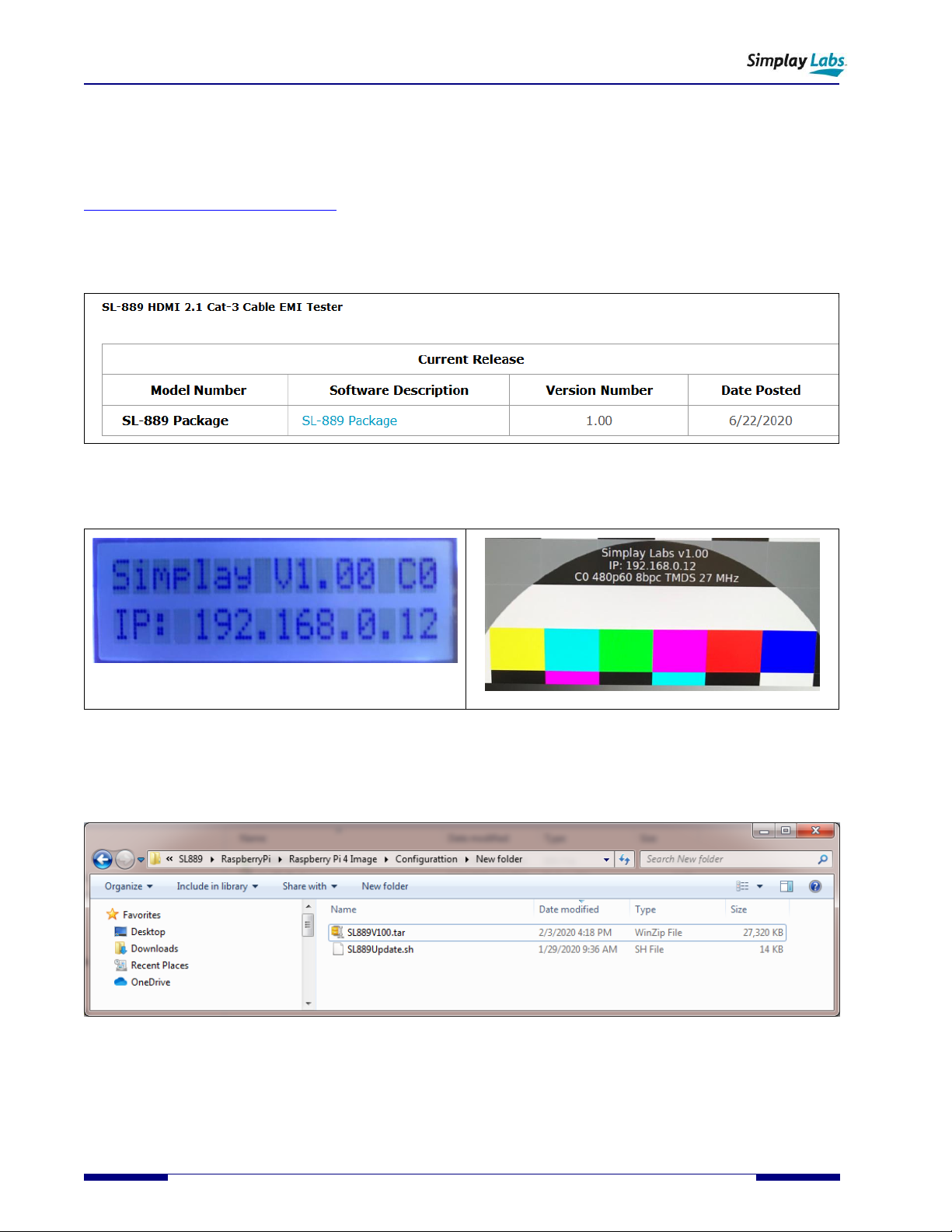
If you received a firmware upgrade notification from Simplay Labs, or if you find issues or problems in the firmware,
you can download the latest SL-889 firmware installation package from the Simplay Labs website:
https://www.simplaylabs.com/support/. Locate the “SL-889”section and click on the hyperlink to download the SL-889
Software Package. (Figure A.1). The *.zip package contains firmware installation files.
Note: To check the firmware version installed on the SL-889, turn the selector knob to “C0”. If the version matches with
the LCD displayed value (Figure A.2), there is no need to update. The version number is also displayed on the C0 screen
monitor output.
Figure A.1. SimplayLabs SL-889 Web Support Page
Figure A.2. SL-889 Firmware Version Display
Unzip the downloaded SL-889_Update_Version1_xx.zip file and store the extracted contents in a local directory on the
host computer. The zip file contains tar file SL889V1XX.tar and SL889Update.sh.

SL-889 HDMI 2.1 Cat-3 Cable EMI Tester
User Guide
Simplay-UG-SL889-1.1 © 2019-2020 Simplay Labs, LLC., 19
All rights reserved. CONFIDENTIAL
A.1. Update Firmware/Scripts/Test Images
Note: You need to have PuTTY and WinSCP installed in your host computer to update the Firmware and scripts. You
can download WinSCP from https://winscp.net/eng/index.php and PuTTY from https://www.putty.org/
1. Open the Shielded RJ45 network connector and use a short ethernet cable to connect directly to
a host computer. Power on the SL-889.
Figure A.3. SL-889 Firmware update via network port
2. Open Network and Sharing Center.
SL-889 HDMI 2.1 Cat-3 Cable EMI Tester
User Guide
20 © 2019-2020 Simplay Labs, LLC., Simplay-UG-SL889-1.1
All rights reserved. CONFIDENTIAL
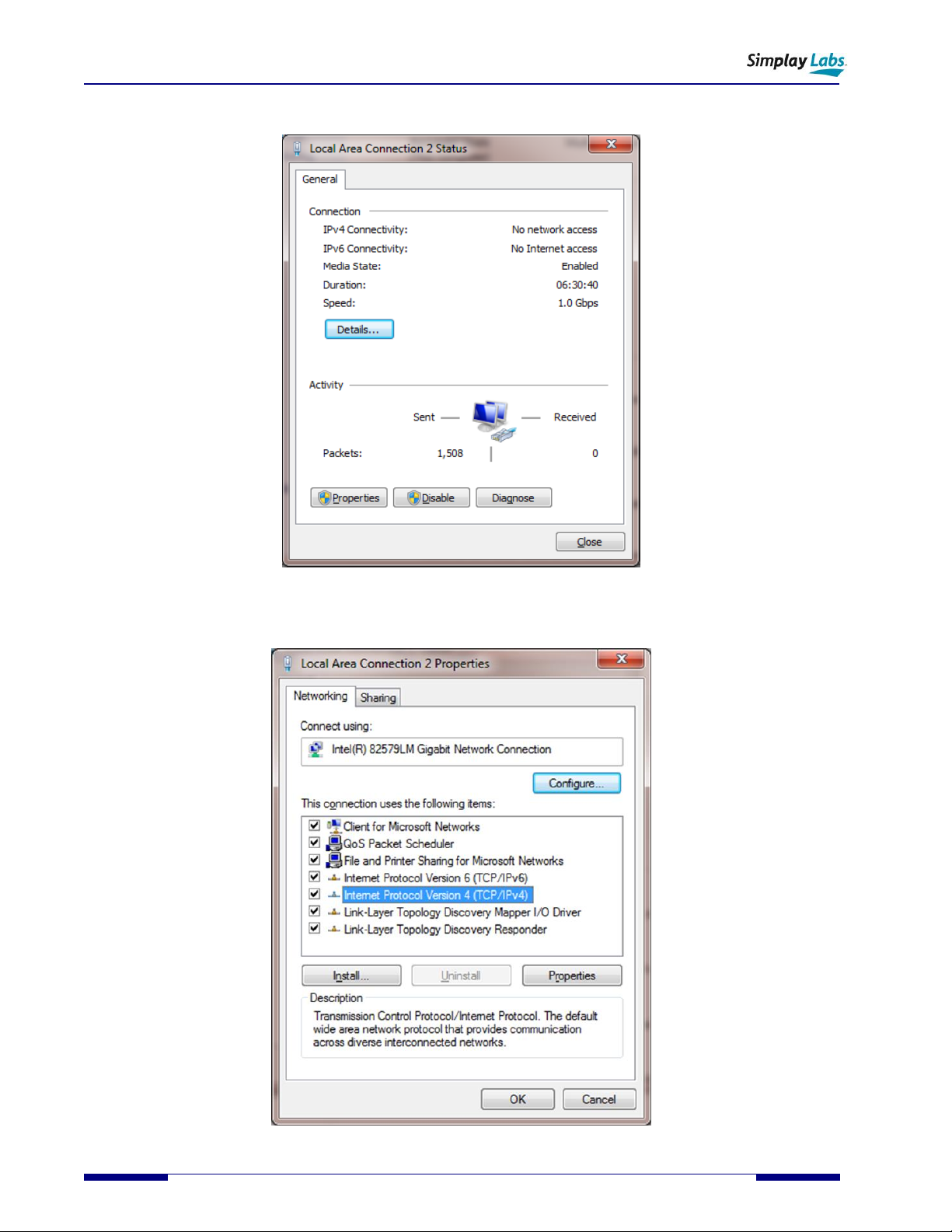
3. Select “Local Area Connection 2”.
4. Select “Properties”.
Table of contents


