Weidmuller IE-SW-PL18M-2GC-16TX Manual

Ethernet Switch –Premium Line
IE-SW-PL18M Series (Managed)
Hardware Installation Guide
Fourth Edition, October 2012
1243410000/03/10.12
Please note:
This document, the detailed manual and any further
product information - if available - can be
downloaded at the internet link:
http://www.weidmueller.com/downloads
Copyright Notice
Copyright 2012 Weidmüller Interface GmbH & Co. KG
All rights reserved.
Reproduction without permission is prohibited.

- 2 -
Package Checklist
Your Ethernet Switch is shipped with the following items. If any of these
items are missing or damaged, please contact your Weidmüller customer
service for assistance.
1 Ethernet Switch IE-SW-PL18M
Hardware Installation Guide
CD-ROM with User’s Manual and Windows Utility (option)
Please download CD-ROM from Internet page
http://www.weidmueller.com/downloads
RJ45 to DB9 Console port cable
Protective caps for unused ports
Optional Accessories
SFP-Transceiver (Fast Ethernet and Gigabit Ethernet modules for different
transmission lengths)
RM-KIT (19” rack mounting kit)
More detailed information in datasheet

- 3 -
Panel Views of
IE-SW-PL18M-2GC-16TX
1. Grounding screw
2. Console port
3. Heat dissipation orifices
4. 6-pin terminal block for DI 1, DI
2, and PWR 2
5. 6-pin terminal block for PWR1
Relay 1, and Relay 2
6. 10/100BaseT(X), ports 1 to 16
7. PWR 1: LED for power input 1
8. PWR 2: LED for power input 2
9. Fault LED
10. MSTR/HEAD LED
11. CPLR/TAIL LED
12. 10/100/1000BaseT(X), port G2
13. 10/100/1000BaseT(X), port G1
14. Label
15. 1000 Mbps LEDs
16. TP port’s 100 Mbps LED
17. TP port’s 10 Mbps LED
18. Article Number
19. Screw hole for Wall Mounting
Kit
20. DIN-Rail Kit

- 4 -
Panel Views of models
IE-SW-PL18M-2GC-14TX2ST
IE-SW-PL18M-2GC-14TX2SC
IE-SW-PL18M-2GC-14TX2SCS
NOTE:
The appearance of models
IE-SW-PL18M-2GC14TX2SCS,
IE-SW-PL18M-2GC14TX2SC and
IE-SW-PL18M-2GC14TX2ST are -
apart from the optical connectors -
identical.
1. Grounding screw
2. Console port
3. Heat dissipation orifices
4. 6-pin terminal block for DI 1, DI 2,
and PWR 2
5. 6-pin terminal block for PWR1
Relay 1, and Relay 2
6. 10/100BaseT(X), ports 1 to 14
7. PWR 1: LED for power input 1
8. PWR 2: LED for power input 2
9. Fault LED
10. MSTR/HEAD LED
11. CPLR/TAIL LED
12. 10/100/1000BaseT(X) Port G2
13. 10/100/1000BaseT(X) Port G1
14. Label
15. 1000 Mbps LEDs
16. TP port’s 100 Mbps LED
17. TP port’s 10 Mbps LED
18. Article Number
19. 100BaseFX Port 16
20. 100BaseFX Port 15
21. 100BaseFX LEDs
22. Screw hole for Wall Mounting Kit
23. DIN-Rail Kit

- 5 -
Mounting Dimensions (unit = mm)
DIN-Rail Mounting
The aluminum DIN-Rail attachment plate should already be fixed to the back
panel of IE-SW-PL18M when you take it out of the box. If you need to
reattach the DIN-Rail attachment plate to IE-SW-PL18M, make sure the stiff
metal spring is situated towards the top, as shown by the following figures.
STEP 1—Insert the top of the
DIN-Rail into the slot just below the
stiff metal spring.
STEP 2—The DIN-Rail attachment
unit will snap into place as shown in
the following illustration.
To remove the IE-SW-PL18M from the DIN-Rail, simply reverse Steps 1 and
2 above.

- 6 -
ATEX Information
1. Certification number DEMKO 11 ATEX 150191X
2. Ambient range (-40°C ≤Tamb ≤75°C)
3. Certification string (Ex nC IIC T4)
4. Standards covered ( EN60079-0:2006, EN60079-15:2005)
5. The conditions of safe usage:
The Ethernet Communication Devices are to be mounted in an IP54
enclosure and used in an area of not more than pollution degree 2 as
defined by IEC60664-1.
A 4mm2 conductor must be used when connection to the external
grounding screw is utilized.
Conductors suitable for use in an ambient temperature of 93°C must be
used for the Power Supply Terminal.
Provisions shall be made, either in external to the apparatus, to prevent
the rated voltage being exceeded by the transients disturbances of more
than 40%.
Wiring Requirements
WARNING
Do not disconnect modules or wires unless power has been
switched off or the area is known to be non-hazardous. The
devices may only be connected to the supply voltage shown on
the type plate. The devices are designed for operation with a
Safety Extra-Low Voltage. Thus, they may only be connected to
the supply voltage connections and to the signal contact with the
Safety Extra-Low Voltages (SELV) in compliance with IEC950/
EN60950/ VDE0805.
ATTENTION
This unit is a built-in type. When the unit is installed in another
piece of equipment, the equipment enclosing the unit must
comply with fire enclosure regulation IEC 60950/EN60950 (or
similar regulation).
ATTENTION
Safety First!
Be sure to disconnect the power cord before installing and/or
wiring your Ethernet Switch.
Calculate the maximum possible current in each power wire and
common wire. Observe all electrical codes dictating the
maximum current allowable for each wire size.
If the current goes above the maximum ratings, the wiring could
overheat, causing serious damage to your equipment.

- 7 -
You should also pay attention to the following points:
Use separate paths to route wiring for power and devices. If power wiring
and device wiring paths must cross, make sure the wires are perpendicular
at the intersection point
NOTE: Do not run signal or communications wiring and power wiring
through the same wire conduit. To avoid interference, wires with different
signal characteristics should be routed separately
You can use the type of signal transmitted through a wire to determine
which wires should be kept separate. The rule of thumb is that wiring that
shares similar electrical characteristics can be bundled together
Separate input wiring and output wiring
We advise that you label wiring to all devices in the system when
necessary.
Grounding the IE-SW-PL18M
Grounding and wire routing help limit the effects of noise due to
electromagnetic interference (EMI). Run the ground connection from the
ground screw to the grounding surface prior to connecting devices.
ATTENTION
This product is intended to be mounted to a well-grounded
mounting surface such as a metal panel.
Wiring the Relay Contact
IE-SW-PL18M-Switches have two sets of relay outputs - relay 1 and relay 2.
Each relay contact consists of the two contacts of the terminal block on the
top panel of IE-SW-PL18M-Switch. You can refer to the next section for
detailed instructions on how to connect the wires to the terminal block
connector, and how to attach the terminal block connector to the terminal
block receptor.
In this section, we will explain the meaning of the two contacts used to
connect the Relay Contact.
FAULT:
The two sets of relay contacts of
the 6-pin terminal block connector
are used to detect user-configured
events. The two wires attached to
the fault contacts form an open
circuit when a user-configured
event is triggered. If a
user-configured event does not
occur, the fault circuit remains
closed.

- 8 -
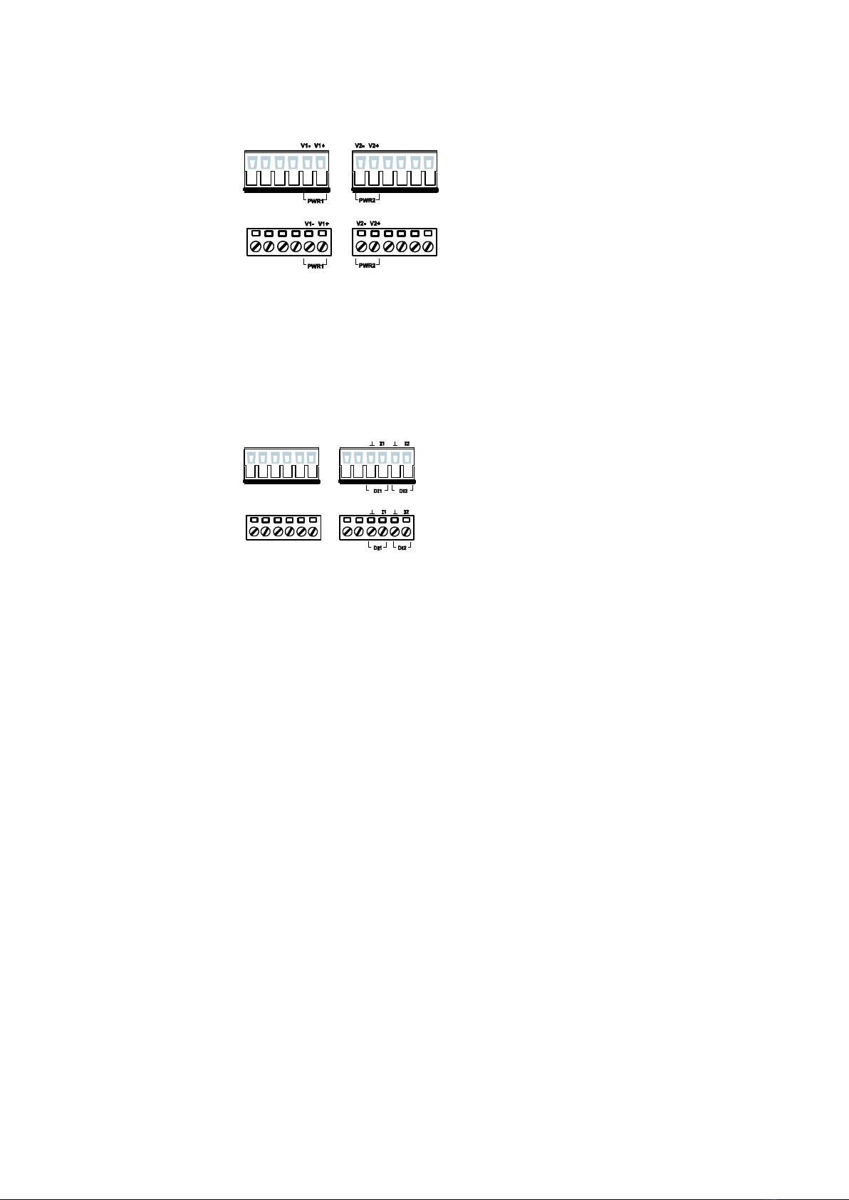
Wiring the Redundant Power Inputs
IE-SW-PL18M-Switches have two sets of power inputs - power input 1 and
power input 2 –located on the 6-pin terminal block connector on the top
panel of the device. See sketch below how to connect.
STEP 1: Insert the
negative/positive DC wires into
the V-/V+ terminals, respectively.
STEP 2: To keep the DC wires
from pulling loose, use a small
flat-blade screwdriver to tighten
the wire-clamp screws on the front
of the terminal block connector.
STEP 3: Insert the plastic terminal
block connector prongs into the
terminal block receptor, which is
located on the switch’s top panel.
Wiring the Digital Inputs
IE-SW-PL18M-Switches have two sets of digital inputs, DI 1 and DI 2. Each
DI consists of two contacts of the 6-pin terminal block connector on Switch´s
top panel, which are used for Switch´s two DC inputs. The top and front
views of one of the terminal block connectors are shown here.
STEP 1: Insert the negative
(ground)/positive DI wires into the ┴
/I1 terminals, respectively.
STEP 2: To keep the DI wires from
pulling loose, use a small flat-blade
screwdriver to tighten the wire-clamp
screws on the front of the terminal
block connector.
STEP 3: Insert the plastic terminal
block connector prongs into the
terminal block receptor, which is
located on the IE-SW-PL18M´s top
panel.
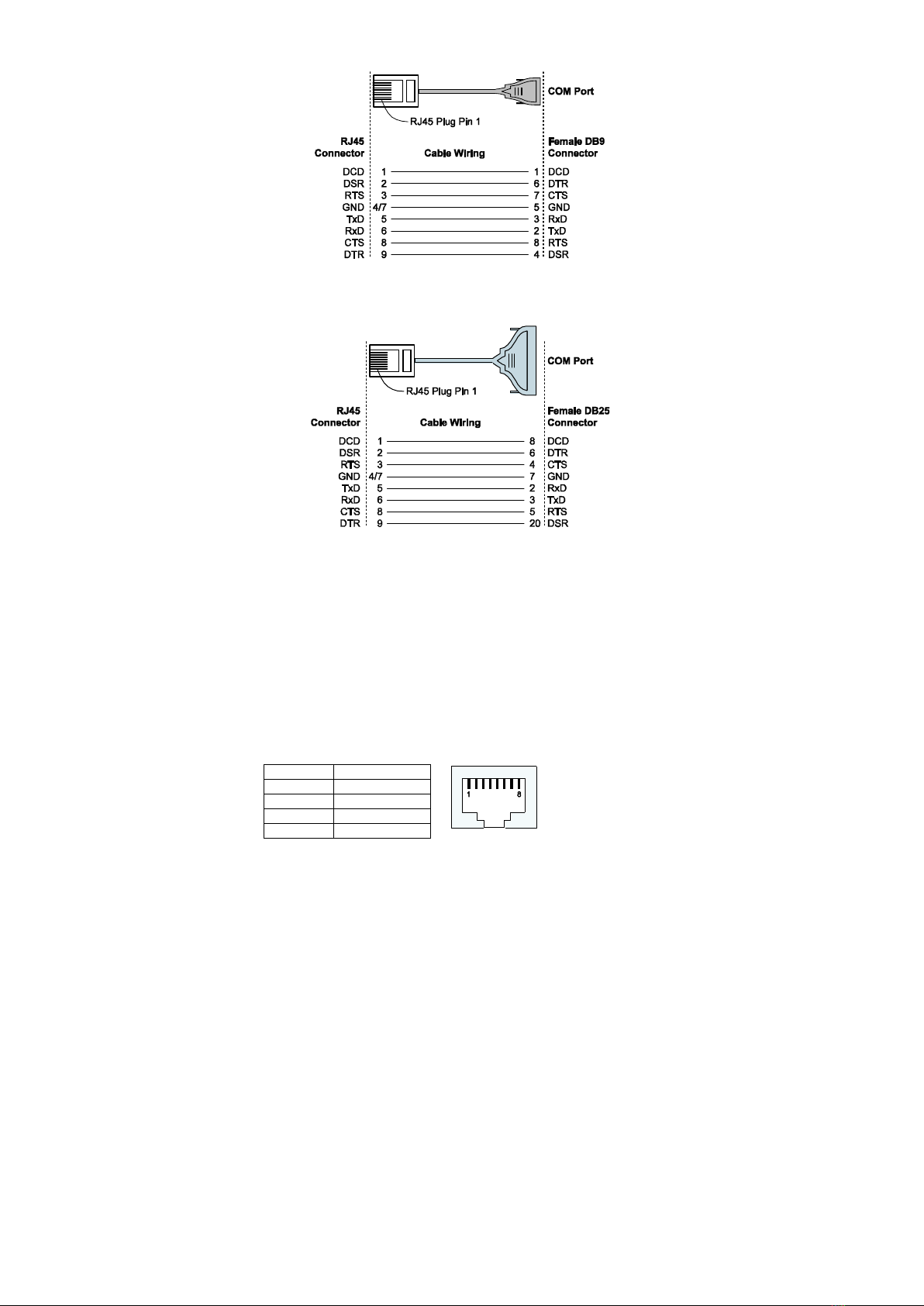
Communication Connections
All models of IE-SW-PL18M-Switches have one RJ45 console port (RS-232
interface), between 14 and 16 10/100BaseTX Ethernet ports. Some models
also have 2 100BaseFX (SC/ST-type connector) fiber ports.
In this section, we present two types of diagrams - Pinout Diagrams and
Cable Wiring Diagrams - to convey information about the ports and the
cables used to connect IE-SW-PL18M Series to other devices:
Pinouts—The meaning of the “Pinouts” diagrams is straightforward. The
diagrams simply display the type of signal passing through each of the port’s
pins.

- 9 -
Cable Wiring—Diagrams labeled “Cable Wiring” present standard cable
wiring schemes for cables used to connect Ethernet Switch ports to other
devices. These diagrams display three pieces of information:
1. When building your own cable, refer to the “pin-to-pin” Cable Wiring
information displayed between the two vertical dashed lines to see
which pin of the connector on the left should be connected to which pin
of the connector on the right.
2. The information to the left of the left vertical dashed lines gives the
pinouts of the relevant Ethernet Switch port.
3. The information to the right of the right vertical dashed line gives the
pinouts of the opposing device’s port.
NOTE
1. The pin numbers for male DB9 and DB25 connectors, and
hole numbers for female DB9 and DB25 connectors are
labeled on the connector. However, the numbers are typically
quite small, so you may need to use a magnifying glass to see
the numbers clearly.
2. The pin numbers for both 8-pin and 10-pin RJ45 connectors
(and ports) are typically not labeled on the connector (or port).
Refer to the following Pinout and Cable Wiring diagrams to
see how RJ45 pins are numbered
RS-232 Connection
IE-SW-PL18M Series has one RS-232 (10-pin RJ45) console port, located on
the top panel. Use either an RJ45-to-DB9 or RJ45-to-DB25 cable (see the
cable following wiring diagrams) to connect the console port of a
IE-SW-PL18M switch to your PC’s COM port. You may then use a console
terminal program, such as Windows Hyper Terminal, to access the switch
console configuration utility.
RJ45 (10-pin) Console Port Pinouts
Pin
Description
1
------
2
DSR
3
------
4
GND
5
TxD
6
RxD
7
GND
8
------
9
DTR
10
------

- 10 -
RJ45 (10-pin) to DB9 (F) Cable Wiring
RJ45 (10-pin) to DB25 (F) Cable Wiring
10/100BaseT(X) Ethernet Port Connection
The 10/100BaseT(X) ports located on the Switch´s front panel are used to
connect to Ethernet-enabled devices. Most users will choose to configure
these ports for Auto MDI/MDI-X mode, in which case the port’s pinouts are
adjusted automatically depending on the type of Ethernet cable used
(straight-through or cross-over), and the type of device (NIC-type or
HUB/Switch-type) connected to the port.
In what follows, we give pinouts for both MDI (NIC-type) ports and MDI-X
(HUB/Switch-type) ports. We also give cable wiring diagrams for
straight-through and cross-over Ethernet cables.
RJ45 (8-pin, MDI) Port Pinouts
Pin
Signal
1
Tx+
2
Tx-
3
Rx+
6
Rx-
Server
Server

- 11 -
RJ45 (8-pin, MDI-X) Port Pinouts
Pin
Signal
1
Rx+
2
Rx-
3
Tx+
6
Tx-
RJ45 (8-pin) to RJ45 (8-pin) Straight-through Cable Wiring
RJ45 (8-pin) to RJ45 (8-pin) Cross-over Cable Wiring
100BaseFx Ethernet Port Connection
The concept behind the SC/ST port and cable is quite straightforward.
Suppose you are connecting devices I and II. As opposed to electrical signals,
optical signals do not require a circuit in order to transmit data. Consequently,
one of the optical lines is used to transmit data from device I to device II, and
the other optical line is used transmit data from device II to device I, for
full-duplex transmission.
All you need to remember is to connect the Tx (transmit) port of device I to
the Rx (receive) port of device II, and the Rx (receive) port of device I to the
Tx (transmit) port of device II.
SC-Port Pinouts
ST-Port Pinouts

- 12 -
ATTENTION
This is a Class 1 Laser/LED product. To prevent damage to your
eyes, do not stare directly into the laser beam.
LED Indicators
The front panel of IE-SW-PL18M Series contains several LED indicators.
The function of each LED is described in the following table:
LED
Color
State
Description
PWR1
AMBER
On
Power is being supplied to power input
P1.
Off
Power is not being supplied to power
input P1.
PWR2
AMBER
On
Power is being supplied to power input
P2.
Off
Power is not being supplied to power
input P2.
FAULT
RED
On
When the corresponding PORT alarm is
enabled, and a user-configured event is
triggered.
Off
When the corresponding PORT alarm is
enabled and a user-configured event is
not triggered, or when the
corresponding PORT alarm is disabled.
MSTR/HEAD
GREEN
On
When the switch is set as the Master of
the Turbo Ring, or as the Head of the
Turbo Chain.
Blinking
The switch has become the Ring Master
of the Turbo Ring, or the Head of the
Turbo Chain, after the Turbo Ring or
the Turbo Chain is down.
Off
When the switch is not the Master of
this Turbo Ring or is set as the Member
of the Turbo Chain.
CPLR/TAIL
GREEN
On
When the switch coupling function is
enabled to form a back-up path, or
when it's set as the Tail of the Turbo
Chain.
Blinking
When the Turbo Chain is down.
Off
When the switch disables the coupling
function.
10M
(TP)
GREEN
On
TP port’s 10 Mbps link is active.
Blinking
Data is being transmitted at 10 Mbps.
Off
TP port’s 10 Mbps link is inactive.
100M
GREEN
On
TP port’s 100 Mbps link is active.

- 13 -
(TP)
Blinking
Data is being transmitted at 100 Mbps.
Off
TP port’s 100 Mbps link is inactive.
1000M
(TP/SFP)
GREEN
On
TP/SFP port’s 1000 Mbps link is active.
Blinking
Data is being transmitted at 1000 Mbps.
Off
TP/SFP port’s 1000 Mbps link is
inactive.
Specifications
Technology
Standards
IEEE 802.3 for 10BaseT,
IEEE 802.3u for 100BaseT(X) and 100Base FX,
IEEE 802.3ab for 1000BaseT(X),
IEEE 802.3z for 1000BaseSX/LX/LHX/ZX,
IEEE 802.3x for Flow Control,
IEEE 802.1D for Spanning Tree Protocol,
IEEE 802.1w for Rapid STP,
IEEE 802.1Q for VLAN Tagging,
IEEE 802.1p for Class of Service,
IEEE 802.1X for Authentication,
IEEE 802.3ad for Port Trunk with LACP
Protocols
IGMPv1/v2, GMRP, GVRP, SNMPv1/v2c/v3,
DHCP Server/Client, DHCP Option 66/67/82,
BootP, TFTP, SNTP, SMTP, RARP, RMON,
HTTP, HTTPS, Telnet, SSH, Syslog, IPv6, LLDP,
IEEE 1588 PTP, Modbus/TCP, SNMP Inform
MIB
MIB-II, Ethernet-like MIB, P-BRIDGE MIB,
Q-BRIDGE MIB, Bridge MIB, RSTP MIB, RMON
MIB Group 1,2,3,9
Interface
RJ45 Ports
10/100/1000BaseT(X) auto negotiation speed, F/H
duplex mode, and auto MDI/MDI-X connection
Fiber Ports
Optional 100BaseFX (SC/ST connector) and
1000BaseSFP slot
Console Port
RS-232 (10-pin RJ45)
LED Indicators
PWR1, PWR2, FAULT, 10/100M (TP port), 100M
(fiber port), 1000M, MSTR/HEAD and CPLR/TAIL
Alarm Contact
Two relay outputs with current carrying capacity of
1A @ 24 VDC
Digital Input
Two inputs with the same ground, but electrically
isolated from the electronics
• For state ―1‖: +13 to +30V
• For state ―0‖: -30 to +3V
• Max. input current: 8 mA

- 14 -
Optical Fiber-100BaseFX
Optical Fiber-1000BaseSX/LX/LHX
SX
LX
LHX
Wavelength
850 nm
1310 nm
1310 nm
Max. Tx
-4 dBm
-3 dBm
1 dBm
Min. Tx
-9.5 dBm
-9.5 dBm
-4 dBm
Rx Sensitivity
-18 dBm
-20 dBm
-24 dBm
Link Budget
8.5 dB
10.5 dB
20 dB
Typical Distance
550m (a)
275m (b)
1100m (c)
550m (d)
10km (e)
40km (e)
Saturation
0 dBm
-3 dBm
-3 dBm
a. [50/125 μm, 400 MHz*km] cable b. [62.5/125 μm, 200 MHz*km] cable
c. [50/125 μm, 800 MHz*km] cable d. [62.5/125 μm, 500 MHz*km] cable
e. [9/125 μm, 3.5 PS/(nm*km)] cable
10A
10B
20A
20B
Wavelength
TX:1310nm
RX:1550nm
TX:1550nm
RX:1310nm
TX:1310nm
RX:1550nm
TX:1550nm
RX:1310nm
Max. Tx
-3 dBm
-3 dBm
-2 dBm
-2 dBm
Min. Tx
-9 dBm
-9 dBm
-8 dBm
-8 dBm
Rx Sensitivity
-21 dBm
-21 dBm
-23 dBm
-23 dBm
Link Budget
12 dB
12 dB
15 dB
15 dB
Typical Distance
10 km
10 km
20 km
20 km
Saturation
-1 dBm
-1 dBm
-1 dBm
-1 dBm
a. [50/125 μm, 400 MHz*km] cable b. [62.5/125 μm, 200 MHz*km] cable
c. [50/125 μm, 800 MHz*km] cable d. [62.5/125 μm, 500 MHz*km] cable
e. [9/125 μm, 3.5 PS/(nm*km)] cable
Power
Input Voltage
24 VDC (12 to 45 VDC), redundant inputs
Input Current (@24V)
0.51A: IE-SW-PL18M-2GC-16TX
0.61A: IE-SW-PL18M-2GC14TX2SC/2ST/2SCS
Connection
Two removable 6-pin terminal blocks
Overload Current Protect.
Present
Reverse Polarity Protection
Present
Mechanical
Casing
IP30 protection, metal case
Dimensions
95 135 140 mm (W H D)
Weight
1.63 kg
Installation
DIN-Rail, Wall Mounting
Environment
Operating Temperature
0 to 60°C (32 to 140°F)
-40 to 75°C (-40 to 167°F) for -T models

- 15 -
Storage Temperature
-40 to 85°C (-40 to 185°F)
Ambient Relative Humidity
5% to 95% (non-condensing)
Regulatory Approvals
Safety
UL60950-1, UL 508
CSA C22.2 No. 60950-1, EN60950-1
Hazardous Location
UL/cUL Class I, Division 2, Groups A, B, C, and
D, ATEX, Zone 2, Ex nC IIC
EMI
FCC Part 15, CISPR (EN55022) class A
EMS
EN61000-4-2 (ESD), Level 2
EN61000-4-3 (RS), Level 3
EN61000-4-4 (EFT), Level 2
EN61000-4-5 (Surge), Level 3
EN61000-4-6 (CS), Level 3
EN61000-4-8
EN61000-4-11
EN61000-4-12
Shock
IEC60068-2-27
Freefall
IEC60068-2-32
Vibration
IEC60068-2-6
WARRANTY
5 years
Weidmüller gives a 5 year warranty on this product in accordance with the
warranty terms as described in the general conditions of sale of the Weidmüller
company which has sold the products to you. Weidmüller warrants to you that
such products the defects of which have already existed at the time when the
risk passed will be repaired by Weidmüller free of charge or that Weidmüller
will provide a new, functionally equivalent product to replace the defective one.
Safe where expressly described otherwise in writing in this catalogue/product
description, Weidmüller gives no warranty or guarantee as to the
interoperability in specific systems or as to the fitness for any particular
purpose. To the extent permitted by law, any claims for damages and
reimbursement of expenses, based on whatever legal reason, including contract
or tort, shall be excluded. Where not expressly stated otherwise in this warranty,
the general conditions of purchase and the expressive liability commitments
therein of the respective Weidmüller company which has sold the products to
you shall be applicable.
Contact Information
Weidmüller Interface GmbH & Co. KG
Postfach 3030
32760 Detmold
Klingenbergstraße 16
32758 Detmold
Germany
Phone +49 (0) 5231 14-0
Fax +49 (0) 5231 14-2083
E-Mail info@weidmueller.com
Internet www.weidmueller.com
This manual suits for next models
4
Table of contents
Other Weidmuller Network Router manuals
Popular Network Router manuals by other brands

LevelOne
LevelOne WAC-2000 user manual

PolyGard
PolyGard MGC2-20 user manual

Huawei
Huawei Enterprise S2700 Series Configuration guide

IntesisBox
IntesisBox IBOX-BAC Series Installation sheet

SMC Networks
SMC Networks 7301TA installation guide

Matrix Switch Corporation
Matrix Switch Corporation MSC-XD88S product manual