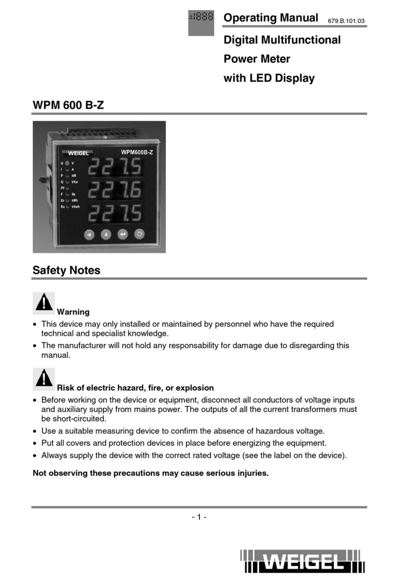
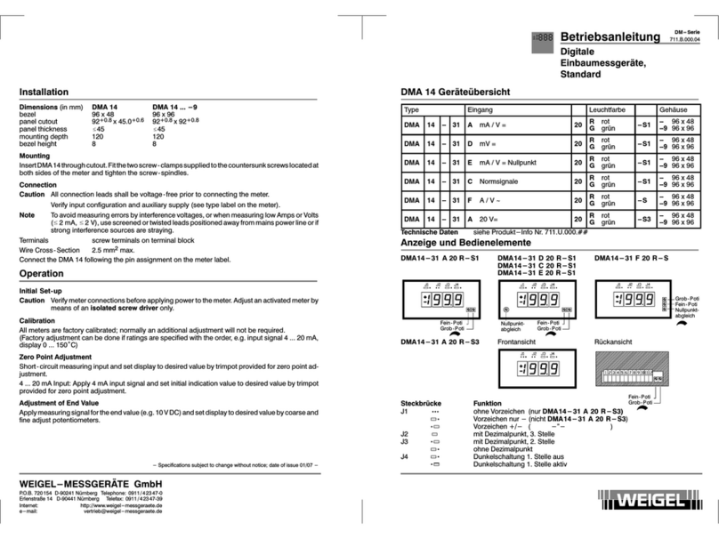
Weigel WPM 735 E User manual

Operating Manual
Digital Multifunctional
Power Meter
with LCD Display
- 1 -
679.B.121.01
WPM 735 E
WPM 735 P
Contents
1. Safety Notes..............................................................................................................2
2. General Information...................................................................................................3
3. Dimensions ...............................................................................................................4
4. Connection ................................................................................................................5
4.1. Connection diagrams ................................................................................................5
4.2. Terminals ..................................................................................................................6
4.3. Installing and connecting the meter ...........................................................................7
5. Display and Keys.......................................................................................................8
5.1. LCD Display ..............................................................................................................8
5.2. Key functions.............................................................................................................8
6. Displaying Measured Values .....................................................................................9
6.1. Reading the real-time values .....................................................................................9
6.2. 4-Quadrant measurement and display.....................................................................10
6.3. Reading the energy values...................................................................................... 10
7. Calculation Methods ................................................................................................12
7.1. Demand ..................................................................................................................12
7.2. Energies..................................................................................................................12
7.3. Harmonics............................................................................................................... 12

- 2-
WEIGEL-MESSGERÄTE GmbH
P.O.B. 720 154 D–90241 Nürnberg Phone: 0911 / 4 23 47–0
Erlenstraße 14 D–90441 Nürnberg Fax: 0911 / 4 23 47–39
Management: Phone: 0911 / 4 23 47–94
Internet: http://www.weigel-messgeraete.de
e-mail: vertrieb@weigel-messgeraete.de
8. Programming the Meter ...........................................................................................13
8.1. Start programming...................................................................................................13
8.2. General programming menus ..................................................................................14
8.3. Product-specific programming menus......................................................................15
9. Status Inputs ...........................................................................................................16
10. Pulse Outputs..........................................................................................................16
11. Analog Output .........................................................................................................17
12. Event Monitoring SOE .............................................................................................19
13. Troubleshooting.......................................................................................................20
14. Technical Data ........................................................................................................21
15. Conformity...............................................................................................................21
1. Safety Notes
Warning
•This device may only installed or maintained by personnel who have the required
technical and specialist knowledge.
•The manufacturer will not hold any responsability for damage due to disregarding this
manual.
Risk of electric hazard, fire, or explosion
•Before working on the device or equipment, disconnect all conductors of voltage inputs
and auxiliary supply from mains power. The outputs of all the current transformers must
be short-circuited.
•Use a suitable measuring device to confirm the absence of hazardous voltage.
•Put all covers and protection devices in place before energizing the equipment.
•Always supply the device with the correct rated voltage (see the label on the device).
Not observing these precautions may cause serious injuries.

Operating Manual
Digital Multifunctional
Power Meter
with LCD Display
- 3 -
679.B.121.01
2. General Information
WPM 735 is a multi-functional power meter, integrating data acquisition and control into a
whole. It can take the place of numerous meters, transducers, and other components.
WPM 735 is equipped with an RS485 communication port, so it can be integrated into any
electric power monitoring system. Using the configuration software, all measured values
and events can be read out, and the meter settings can be carried out easily. This software
can be downloaded from www.weigel-messgeraete.de
WPM 735 P additionally provides a PROFIBUS communication port with a maximum data
transfer rate of 1.5 Mbits/sec which enables real-time monitoring.
WPM 735 enables true effective measurement, able to carry out accurate measurement of
highly non-linear loads. Harmonics up to the 31st harmonic can be read out. Dozens of
measured values and minimum/maximum values can be viewed on the display or read out
via software.
WPM 735
Basic unit Addon module
Side view Rear view Rear view
Note: The addon module and the connection layout are different on WPM 735 E and on
WPM 735 P as well on custom meter versions!

- 4-
WEIGEL-MESSGERÄTE GmbH
P.O.B. 720 154 D–90241 Nürnberg Phone: 0911 / 4 23 47–0
Erlenstraße 14 D–90441 Nürnberg Fax: 0911 / 4 23 47–39
Management: Phone: 0911 / 4 23 47–94
Internet: http://www.weigel-messgeraete.de
e-mail: vertrieb@weigel-messgeraete.de
3. Dimensions
Addon
module

Operating Manual
Digital Multifunctional
Power Meter
with LCD Display
- 5 -
679.B.121.01
4. Connection
The WPM 735 is connected by 3 terminal strips which can be pulled out and inserted, thus
facilitating on-site wiring and maintenance. The terminal strip with current connections (on
top of the meter) can be fixed by two screws in order to prevent unintentional pull-out and
thus prevent dangerous induction voltages when current terminals are not connected.
4.1. Connection diagrams
3-phase 4-wire system
3-phase 3-wire system, 3 CTs 3-phase 3-wire system, 2 CTs

- 6-
WEIGEL-MESSGERÄTE GmbH
P.O.B. 720 154 D–90241 Nürnberg Phone: 0911 / 4 23 47–0
Erlenstraße 14 D–90441 Nürnberg Fax: 0911 / 4 23 47–39
Management: Phone: 0911 / 4 23 47–94
Internet: http://www.weigel-messgeraete.de
e-mail: vertrieb@weigel-messgeraete.de
4.2. Terminals
Basic unit
Addon module
Terminal assignment of basic unit
No. Terminal Description No. Terminal Description
1 L/+ auxiliary supply 15 RS485A+ RS485+
2 NC not connected 16 RS485B– RS485 –
3 N/– auxiliary supply 17 SHLD shield
4 NC not connected 18 NC not connected
5 FG protective ground 19 NC not connected
6 NC not connected 20 A1 analog output +
7 NC not connected 21 AG analog output –
8 NC not connected 22 VN neutral
9 I32 current L3 23 NC not connected
10 I31 current L3 24 V3 voltage L3
11 I22 current L2 25 NC not connected
12 I21 current L2 26 V2 voltage L2
13 I12 current L1 27 NC not connected
14 I11 current L1 28 V1 voltage L1

Operating Manual
Digital Multifunctional
Power Meter
with LCD Display
- 7 -
679.B.121.01
Terminal assignment of addon module
No. Terminal WPM 735 E only No. Terminal WPM 735 P only
29 P2– 29 RB termination resistor B
30 P2+
pulse output
reactive energy 30 P– Profibus –
31 P1– 31 P+ Profibus +
32 P1+
pulse output
active energy 32 RA termination resistor A
33 Scom supply +30V
status inputs
33 SHLD shield
34 S8 status input 8 34 NC not connected
35 S7 status input 7 35 NC not connected
36 S6 status input 6 36 NC not connected
37 S5 status input 5 37 NC not connected
38 S8 status input 4 38 NC not connected
39 S7 status input 3 39 NC not connected
40 S6 status input 2 40 NC not connected
41 S5 status input 1 41 NC not connected
42 NC not connected 42 NC not connected
Notes on WPM 735 E
•For the status inputs, external switch
contacts are required.
•For the analog and pulse outputs see the
according descriptions below
4.3. Installing and connecting the meter
♦Make sure that all the lines are de-energized and the outputs of the current transducers
are short-circuited.
♦Insert the meter into the panel cutout.
♦Fix the meter using the two plastic clips.
♦Connect the meter according the terminal assignment (also see the print on the meter).
♦Insert the terminal strips into the meter and fasten the two screws of the terminal strip
with the current inputs (upper terminal strip).

- 8-
WEIGEL-MESSGERÄTE GmbH
P.O.B. 720 154 D–90241 Nürnberg Phone: 0911 / 4 23 47–0
Erlenstraße 14 D–90441 Nürnberg Fax: 0911 / 4 23 47–39
Management: Phone: 0911 / 4 23 47–94
Internet: http://www.weigel-messgeraete.de
e-mail: vertrieb@weigel-messgeraete.de
5. Display and Keys
5.1. LCD Display
Displays for:
A: THD (Total Harmonic Distortion)
B: Harmonics
C: Phases* and Quadrants**
D: Real-time values
E: Units of real-time values
F: Communication
G: Energy values and programming
H: Unit of energy
J: Keys
K: Status inputs (WPM 735 E only)
L: Pulse outputs (WPM 735 E only)
M: Quadrants for energy
N: SOE functions/Programming menu
O: Programming
P: Real-time measuring quantity
Q: Unbalance indication
R: Min./Max. values and demand
1: Logo
2: Product name
* The phases are indicated by A, B, C:
A = L1, B = L2, C = L3
** none (+) = import, -= export
= capacitive, = inductive
MAX
TH D
MIN
DMD
V
A
W
A B
CA
BC
S1 S2 S3 S4 S5 S6 S7 S8
Unbal
WPM735
WEIGEL
5.2. Key functions
in programming mode
Key in display mode
when viewing when changing
submenu up - move cursor left
submenu down - move cursor right
main menu down menu down decrease value of
selected digit
main menu up menu up increase value of
selected digit
page energies* change setting confirm setting
enter programming mode leave programming
mode
leave programming
mode
* also DATE, TIME, and INFO with SOE option

Operating Manual
Digital Multifunctional
Power Meter
with LCD Display
- 9 -
679.B.121.01
6. Displaying Measured Values
6.1. Reading the real-time values
The measured real-time values can be selected via the main menu and submenus.
♦For paging the main menu, press one of these keys (down) (up).
•For paging in a submenu, press one of these keys (back) (forward).
Display Main menu Submenus
Voltages L-L
Unbalance rate of voltages L-L
Voltages L-N
UVoltage
Unbalance rate of voltages L-N
Phase currents
Unbalance rate of currents
ICurrent
Neutral current
Total active power
PActive power
Phase active powers
Total reactive power
QReactive power
Phase reactive powers
Total apparent power
SApparent power
Phase apparent powers
Total power factor
PF Power factor
Phase power factors
FFrequency -
I: Average current demand and max. demand
I: Date/time* of current maximum demand
P: Average active power demand and max. demand
P: Date/time* of active power maximum demand
Q: Average reactive power demand and max. demand
Q: Date/time* of reactive power maximum demand
S: Average apparent power demand and max. demand
MAX DMD Demand and
max. demand
* Time of occurrence:
1. row: year, month
2. row: day, hour
3. row: minute, second S: Date/time* of apparent power maximum demand

- 10 -
WEIGEL-MESSGERÄTE GmbH
P.O.B. 720 154 D–90241 Nürnberg Phone: 0911 / 4 23 47–0
Erlenstraße 14 D–90441 Nürnberg Fax: 0911 / 4 23 47–39
Management: Phone: 0911 / 4 23 47–94
Internet: http://www.weigel-messgeraete.de
e-mail: vertrieb@weigel-messgeraete.de
Display Main menu Submenus
Total Harmonic Distortion (THD) of voltages
THD U Voltage
harmonics HD01 ... HD31: individual harmonics of voltages
Total Harmonic Distortion (THD) of currents
THD I Current
harmonics HD01 ... HD31: individual harmonics of currents
I: Maximum phase currents
P: Maximum values of total active power
Q: Maximum values of total reactive power
S: Maximum values of total apparent power
THD I: Maximum THD of currents
MAX Maximum values
THD U: Maximum THD of voltages
I: Minimum phase currents
P: Minimum values of total active power
Q: Minimum values of total reactive power
S: Minimum values of total apparent power
THD I: Minimum THD of currents
MIN Minimum values
THD U: Minimum THD of voltages
6.2. 4-Quadrant measurement and display
The currents and powers are measured in 4 quadrants:
6.3. Reading the energy values
One energy values can be displayed at a time in addition to current the real-time value
display.
♦When any real-time value is displayed, press this key , once or several times.

Operating Manual
Digital Multifunctional
Power Meter
with LCD Display
- 11 -
679.B.121.01
The following values are displayed one after the other:
Display Unit Display of energy value and other
kWh Imported inductive active energy
kWh Exported capacitive active energy
kWh Exported inductive active energy
kWh Imported capacitive active energy
kVarh Imported inductive reactive energy
kVarh Exported capacitive reactive energy
kVarh Exported inductive reactive energy
kVarh Imported capacitive reactive energy
kWh Imported inductive and capacitive active energy
kWh Exported inductive and capacitive active energy
kVarh Reactive 1st and 2nd quadrant energy
kVarh Reactive 3rd and 4th quadrant energy
DATE - Date: year - month - day
TIME - Time: hour - minute - second
INFO - Error message: 0 = no error, 1 = error
Digits 1-4: reserved
Digit 5: sampling error
Digit 6: configuration error
Digit 7: accuracy error
Digit 8: external error

- 12 -
WEIGEL-MESSGERÄTE GmbH
P.O.B. 720 154 D–90241 Nürnberg Phone: 0911 / 4 23 47–0
Erlenstraße 14 D–90441 Nürnberg Fax: 0911 / 4 23 47–39
Management: Phone: 0911 / 4 23 47–94
Internet: http://www.weigel-messgeraete.de
e-mail: vertrieb@weigel-messgeraete.de
7. Calculation Methods
7.1. Demand
The demand values are determined as follows:
The accumulated electrical parameter within a demand time period divided by the demand
time length.
The demand time is fixed to 15 minutes.
The following figure illustrates the calculation method:
Am Ende des Zeitintervalls wird
die Berechnung aktualisiert The demand value is
the average value at
the end of the
calculation interval.
calculation interval
demand time 15 min
calculation interval
demand time 15 min
Time
(minutes)
The calculation is updated at the
end of the calculation interval.
7.2. Energies
WPM 735 bidirectionally measures the active and reactive energies in 4 quadrants.
The energy values are counted up to 99,999,999.9 and then counting restarts from zero.
The decimal place is not displayed.
The polarity of energies (import/export, inductive/capacitive) is identical to those of power,
both conforming to the stipulations of IEC standards, see 6.2.
7.3. Harmonics
WPM 735 provides measurement of harmonics up to the 31st harmonic for voltage and
current as well as total harmonic distortion (THD) and K factor of current.
The portion of harmonics is given by the percentage of fundamental harmonics and have
one digit after the decimal point. That is to say, when the value of the fundamental and
harmonic is 1000, that is 100.0% of the effective value of the fundamental harmonic, others
are by analogy.
The THD refers to the total of higher harmonics except fundamental harmonics, and it is
calculated according to the following formula:
∑
=
=
=
ni
i
i
X
THD
2
2

Operating Manual
Digital Multifunctional
Power Meter
with LCD Display
- 13 -
679.B.121.01
The K factor is calculated as follows:
∑∑ ×=
=
=
=
=
ni
i
ni
iii
KXXi
1
2
1
2
)(
i: Harmonic order
i
X: Percentage of the effective value of each harmonic to that of the fundamental
harmonic
n: Highest harmonic, here 31
Notes:
•Each harmonic and the THD can be read from the display or read out through
communication.
•K factor can only be read out through communication.
8. Programming the Meter
8.1. Start programming
The password must be entered for changing the meter settings:
♦Press this key .
PROG
CODE ** is shown.
♦Press this key to set a value.
** is shown. (The underscore indicates the active digit.)
♦Press this key twice.
1is shown. (1 is the preset password.)
♦Press this key to confirm the entry.
Notes
•For key functions see 5.2.
•The underscore _ indicates the active digit.
•When selecting the digit to the left by this key , then, if necessary and possible, an
additional digit is automatically added.
•If the leading digit is a 0, this digit will be blanked when selecting the digit to the right by
this key .

- 14 -
WEIGEL-MESSGERÄTE GmbH
P.O.B. 720 154 D–90241 Nürnberg Phone: 0911 / 4 23 47–0
Erlenstraße 14 D–90441 Nürnberg Fax: 0911 / 4 23 47–39
Management: Phone: 0911 / 4 23 47–94
Internet: http://www.weigel-messgeraete.de
e-mail: vertrieb@weigel-messgeraete.de
8.2. General programming menus
Menu Description Value range Notes
CT-PR CT primary value 1 ... 50.000
CT-SE CT secondary value 5 fixed,
cannot be changed
PT-PR Voltage transformer primary
value
1 ... 5000 Higher values can be set but
will not be taken over.
PT-SE Voltage transformer secon-
dary value
1 ... 200 Changing the voltage
transformer range will in
general not be useful.
Set PT-PR and PT-SE to the
same value!
MODE System type: 4-wire star or
3-wire delta
4Y, 3d
ADDR RS485 meter address 1 ... 247
BAUD RS485 baud rate 4800, 9600,
19200, 38400
CLR-MClear minimum and
maximum values
YES, NO
CLR-EReset energy counters YES, NO
CLR-DClear demand values YES, NO
CLR-SClear events YES, NO
When selecting YES
the values are reset.
After confirmation NO
is displayed again.
.
.
.
In this section the product-specific programming menus are present, see
8.3.
RESET Reset meter to factory
settings
YES, NO When selecting YES the
values are reset.
After confirmation NO is
displayed again.
VER Display of firmware version fixed,
cannot be changed
CODE Enter password 0 ... 99 1 is the preset
password.

Operating Manual
Digital Multifunctional
Power Meter
with LCD Display
- 15 -
679.B.121.01
8.3. Product-specific programming menus
Menu Description Value range Notes
P1-ob Energy value applied to
active energy pulse output
nULL
IMP
EXP
none
imported active energy
exported active energy
P2-ob Energy value applied to
reactive energy pulse
output
nULL
IMP
EXP
none
imported reactive energy
exported reactive energy
P-NUM pulse weight 1000 ... 5000 Higher values can be set but will
not be taken over.
An-ob Measured quantity applied
to analog output
nULL
UA
UB
UC
UAB
UBC
UCA
IA
IB
IC
P
q
PF
F
none
voltage L1-N
voltage L2-N
voltage L3-N
voltage L1-L2
voltage L2-L3
voltage L3-L1
current L1
current L2
current L3
total active power
total reactive power
power factor
frequency
An-MU Scaling factor for analog
output
10 ... 100 The set value is internally
multiplicated by 0.1
e.g. 10 corresponds to 1.0
11 corresponds to 1.1 and so on
100 corresponds to 10.0

- 16 -
WEIGEL-MESSGERÄTE GmbH
P.O.B. 720 154 D–90241 Nürnberg Phone: 0911 / 4 23 47–0
Erlenstraße 14 D–90441 Nürnberg Fax: 0911 / 4 23 47–39
Management: Phone: 0911 / 4 23 47–94
Internet: http://www.weigel-messgeraete.de
e-mail: vertrieb@weigel-messgeraete.de
9. Status Inputs
WPM 735 E is equipped with 8 status input channels which can be used, e.g., to acquire
switch positions.
The meter provides a 30 V supply for this purpose.
External contacts can be directly connected.
Note: Since there is a internal supply by the meter, no external supply must be connected.
Otherwise, the meter can be damaged.
10. Pulse Outputs
WPM 735 E is equipped with two pulse outputs for energy:
•P1 output supplies pulses for the total active energy. There are three possible settings:
imported or exported active energy, or not active
•P2 output supplies pulses for the total reactive energy. There are three possible settings:
imported or exported reactive energy, or not active
(Programming see 8.3.)

Operating Manual
Digital Multifunctional
Power Meter
with LCD Display
- 17 -
679.B.121.01
The outputs have open collector optocoupler, max. 50 V, 50 mA
The pulse weigth is adjustable from 1000 to 5000. (Programming see 8.3.)
It depends on current transformer CT and voltage transformer PT settings,
i.e. with 1 kWh/kvarh x CT x PT the set pulse count is supplied.
11. Analog Output
WPM 735 E is equipped with one analog output 4-20 mA, to which one measured quantity
can be assigned to. (Programming see 8.3.)
The burdan shall not exceed 500 Ohms.
By adjusting the scaling factor λ(Programming see 8.3.) the conversion characteristics for
voltage, current, active power, and reactive power can be set (but not for power factor or
frequency).
The figures below illustrate the conversion characteristics:
IAIAIA
IAIA
IA

- 18 -
WEIGEL-MESSGERÄTE GmbH
P.O.B. 720 154 D–90241 Nürnberg Phone: 0911 / 4 23 47–0
Erlenstraße 14 D–90441 Nürnberg Fax: 0911 / 4 23 47–39
Management: Phone: 0911 / 4 23 47–94
Internet: http://www.weigel-messgeraete.de
e-mail: vertrieb@weigel-messgeraete.de
The following formulas show the context of the measured quantity and the output current
A
I:
Quantity Output current
Voltage
()
PTU
mA
mAI
Ue
A×××
−
=
λ
16
4mAmA
PTU
U
I
e
A416 +×
××
=
λ
Current
()
CTI
mA
mAI
Ie
A×××
−
=
λ
16
4mAmA
CTI
I
I
e
A416 +×
××
=
λ
Active power
()
PTCTP
mA
mAI
Pe
A××××
−
=
λ
8
12 mAmA
PTCTP
P
I
e
A128+×
×××
=
λ
Reactive power
()
PTCTQ
mA
mAI
Qe
A××××
−
=
λ
8
12 mAmA
PTCTQ
Q
I
e
A128+×
×××
=
λ
Power factor
()
12
16
4−×
−
=mA
mAI
PF AmAmA
PF
IA416
2
1+×
+
=
Frequency
()
HzHz
mA
mAI
FA3530
16
4+×
−
=mAmA
Hz
HzF
IA416
30
35 +×
−
=
where:
A
I: Output current in mA
e
U: Rated voltage of the meter in V
e
I: Rated current of the meter in A
e
P: Active power fullscale value of the meter in W eee IUP ××= 3
e
Q: Reactive power fullscale value of the meter in Var
PF: Power factor (-1 ... 0 ... 1)
F: Frequency
λ
: Scaling factor in the range of 1 to 10 (default: 1)
CT: Current transformer ratio
PT: Voltage transformer ratio

Operating Manual
Digital Multifunctional
Power Meter
with LCD Display
- 19 -
679.B.121.01
12. Event Monitoring SOE
WPM 735 E provides a function of recording up to 50 SOE events,. The records can be kept
for more than 10 years.
The SOE recording function can record the switch contact positions. When an event occurs,
the meter will automatically record the type of the event such as closing of contact 1. At the
same time, the year, month, day, hour, minute, second, millisecond when the event occurs
will be recorded precisely. The resolution is 2 ms.
The SOE records can be read out through communication.
The structure of SOE event data is as follows:
Byte position Definition Description
0 Type of event 1 = S1
2 = S2
...
8 = S8
1 Status of event 0 = OFF
1 = ON
2 – 3 Millisecond
4 – 5 UNIX clock low word
6 – 7 UNIX clock high word
The basis reference of the UNIX clock is 00:00:00 January 1, 1970 (Greenwich Mean Time).
For time conversion, please pay attention to the time difference of your time zone and
daylight saving time. For MST, there is a 1 hour (2 hours with DST) time difference
compared to standard UNIX time.

- 20 -
WEIGEL-MESSGERÄTE GmbH
P.O.B. 720 154 D–90241 Nürnberg Phone: 0911 / 4 23 47–0
Erlenstraße 14 D–90441 Nürnberg Fax: 0911 / 4 23 47–39
Management: Phone: 0911 / 4 23 47–94
Internet: http://www.weigel-messgeraete.de
e-mail: vertrieb@weigel-messgeraete.de
13. Troubleshooting
Possible problem Possible cause Possible solution
No display after
power-up.
Auxiliary supply may
not be connected.
Check rated voltage on L/+ and N/-
terminals.
Check fuse in auxiliary supply.
Voltage measurement
is not correct.
Check neutral connection.
Check voltage to match rated voltage.
Check voltage transformer ratio or PT
primary and secondary values.
Current measurement
is not correct.
Check current to match rated current.
Check current transformer ratio or CT
primary and secondary values.
measured values are
false or not as
expected.
Power measurement
is not correct.
Check system type setting: 4-wire star
or 3-wire delta
Check phase sequence of voltages and
currents
Check sequence of CT connection
There is no change in
the ON-OFF status
(WPM 735 E only)
Power supply for ON-
OFF is not correct.
Check external contacts
Check external connections
No signal on analog
output (WPM 735 E
only)
The analog output is
set to "nULL" or
wrong measured
quantity
Check analog output settings.
No or not correct
pulses on pulse output
(WPM 735 E only)
The pulse output is
set to "nULL" or
wrong measured
quantity or wrong
pulse weight.
Check pulse output settings.
This manual suits for next models
1
Table of contents
Other Weigel Measuring Instrument manuals