©2019 WEINZIERL ENGINEERING GmbH Page 4/5
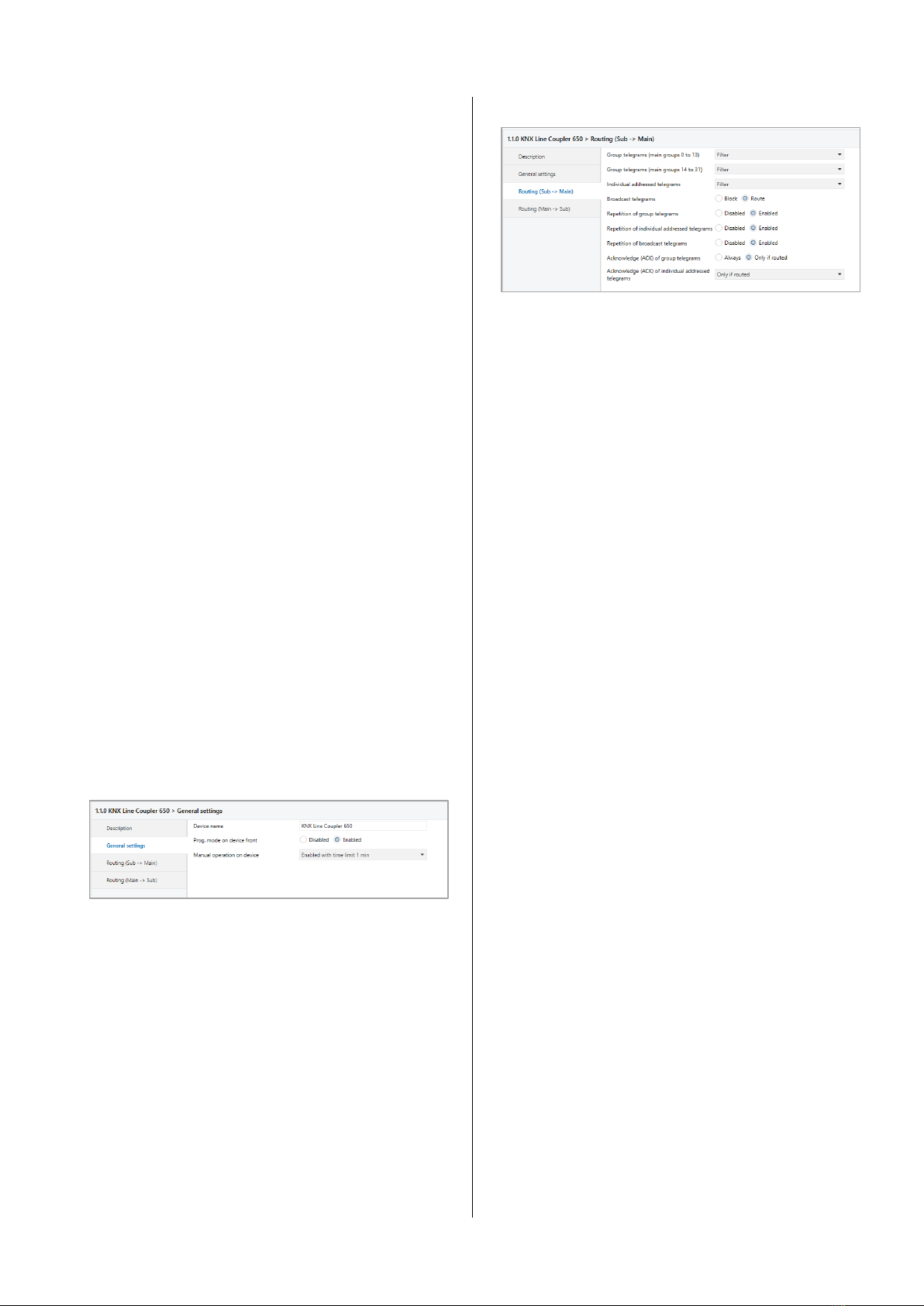
Repetition of individually addressed telegrams
Disabled: The received individually addressed tele-
gram is not resent to the main line in case of
a fault.
Enabled: The received individually addressed tele-
gram is resent up to three times in case of a
fault.
Repetition of broadcast telegrams
Disabled: The received broadcast telegram is not
resent to the main line in case of a fault.
Enabled: The received broadcast telegram is resent
up to three times in case of a fault.
Acknowledge (ACK) of group telegrams
Always: A acknowledge is generated for every re-
ceived group telegram (from the sub line).
Only if routed: A acknowledge is only generated for re-
ceived group telegrams (from the sub line) if
they are routed to the main line.
Acknowledge (ACK) of individually addressed telegrams
Always: A acknowledge is generated for every re-
ceived individual addressed telegram (from
the sub line).
Only if routed: A acknowledge is only generated for re-
ceived individually addressed group tele-
grams (from the sub line) if they are routed
to the main line.
Answer with NACK:Every received individually addressed tele-
gram (from the sub line) is responded to with
NACK (Not acknowledge). This means that
communication with individually addressed
telegrams on the corresponding KNX line is
not possible. Group communication (group
telegrams) is not affected. This setting can
be used to block attempts at manipulation.
When using “Answer with NACK” an access to the
device via the KNX sub line is no longer possible. The
configuration must be performed via the main line.
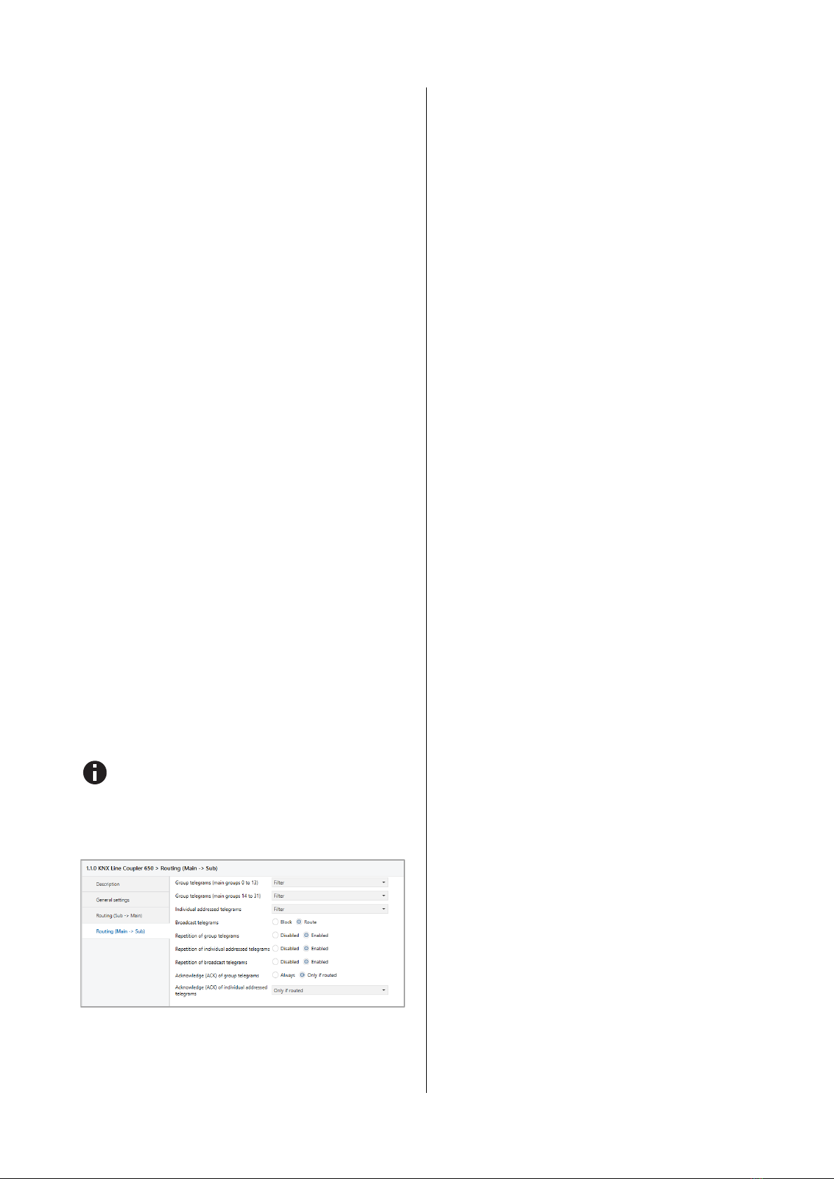
Routing (Main line -> Sub line)
Group telegrams (main group 0 to 13)
Block: No group telegrams of this main group are
routed to the sub line.
Route: All group telegrams of this main group are
routed to the sub line independent of the fil-
ter table. This setting is for test purposes on-
ly.
Filter: The filter table is used to check whether or
not the received group telegram should be
routed to the sub line.
Group telegrams (main group 14 to 31)
Block: No group telegrams of main groups 14 to 31
are routed to the sub line.
Route: All group telegrams of main groups 14 to 31
are routed to the sub line. This setting is for
test purposes only.
Filter: The filter table is used to check whether or
not the received group telegram should be
routed to the sub line.
Individually addressed telegrams
Block: No individually addressed telegrams are
routed to the sub line.
Route: All individually addressed telegrams are
routed to the sub line. This setting is for test
purposes only.
Filter: The individual address is used to check
whether the received individually addressed
telegram should be routed to the sub line.
Broadcast telegrams
Block: No received broadcast telegrams are routed
to the sub line.
Route: All received broadcast telegrams are routed
to the sub line.
Repetition of group telegrams
Disabled: The received group telegram is not resent to
the sub line in case of a fault.
Enabled: The received group telegram is resent up to
three times in case of a fault.
Repetition of individually addressed telegrams
Disabled: The received individually addressed tele-
gram is not resent to the sub line in case of a
fault.
Enabled: The received individually addressed tele-
gram is resent up to three times in case of a
fault.