manuals.online logo
Brands
  1. Home
  2. •
  3. Brands
  4. •
  5. Harwin
  6. •
  7. Cables And Connectors
  8. •
  9. Harwin S-TEK M80-4C1 05S1 Series Manual

Harwin S-TEK M80-4C1 05S1 Series Manual

ASSEMBLY PROCEDURE FOR S-TEK BACKSHELL ADAPTORS
Harwin North America Harwin Europe Harwin Asia
T: +1 603 893 5376 F: +1 603 893 5396 T: +44 (0) 23 9231 4545 F: +44 (0) 23 9231 4590 T: +65 6 779 4909 F: +65 6 779 386
E: [email protected] W: www.harwin.com E: mis@harwin.co.uk W: www.harwin.com E: [email protected] W: www.harwin.com.sg
IS-32 Issue: 4 Date: 01.04.11 C/Note: 11172 Page 1 of 4
This instruction sheet is designed to demonstrate how to assemble Datamate product equipped with
metal backshells. The part numbers include:
M80-4C1XX05S1
M80-4C1XX42S1
M80-4D1XX05S1
M80-4D1XX42S1
Note: Example shown is M80-4C11005S1. Kits includes four ‘E’-clips, two are spare.
Kit of parts is as follows:
Tools required for these products include:
BAND-IT Tie-Dex tool A301 (A590 kit)
Hand Crimp Tool M22520/2-01 with Positioner T5747
Contact insertion tool Z80-280
‘E’-clip tool Z80-300
1 x Band-It Tie Dex
1 x Metal
backshell
1 x Datamate
moulding
2 x
J
ackscrews
4 x ‘E’-clips
Crimp contacts
ASSEMBLY PROCEDURE FOR S-TEK BACKSHELL ADAPTORS
Harwin North America Harwin Europe Harwin Asia
T: +1 603 893 5376 F: +1 603 893 5396 T: +44 (0) 23 9231 4545 F: +44 (0) 23 9231 4590 T: +65 6 779 4909 F: +65 6 779 386
E: [email protected] W: www.harwin.com E: mis@harwin.co.uk W: www.harwin.com E: [email protected] W: www.harwin.com.sg
IS-32 Issue: 4 Date: 01.04.11 C/Note: 11172 Page 2 of 4
1) Feed cables through required length of braiding. It may be advisable to secure the cables together
with electrical tape or similar to prevent wires becoming entangled in braiding. Leave the tape on
until instructed to remove it later in these instructions.
2) Feed Band-It tie over cables and braiding for application later.
3) Feed cabling through ellipse/circular feature of backshell as shown below. Again, securing the cables
together with electrical tape or similar may ease this process.
4) If tape was used, remove it now. Crimp the Datamate contacts onto the wires, and insert the
contacts into the moulding. Please consult the relevant Instruction sheets: for crimping instructions
see Instruction Sheet IS-01 for more details. For contact insertion into moulding see instruction sheet
IS-25. All instruction sheets can be found at http://www.harwin.com/downloads/instructions/.
5) Terminate the braiding to the backshell using the Band-It tie. Harwin strongly recommend that all
terminations are made so that the locking lip of the Band-It Tie Dex is positioned along the longer
portion of the backshell exit to ensure a uniform band and braid compression (see example below).
This also prevents the locking lip of the tie obstructing jackscrew insertion at a later stage. For full
tooling instructions on the Band-It Tie Dex go to http://www.band-it.co.uk/tooling.htm and select
tool A590 for full details.

ASSEMBLY PROCEDURE FOR S-TEK BACKSHELL ADAPTORS
Harwin North America Harwin Europe Harwin Asia
T: +1 603 893 5376 F: +1 603 893 5396 T: +44 (0) 23 9231 4545 F: +44 (0) 23 9231 4590 T: +65 6 779 4909 F: +65 6 779 386
E: [email protected] W: www.harwin.com E: mis@harwin.co.uk W: www.harwin.com E: [email protected] W: www.harwin.com.sg
IS-32 Issue: 4 Date: 01.04.11 C/Note: 11172 Page 3 of 4
Fig.1
Fig.2
6) Once braiding has been terminated as described and shown on page 2, and the locking lip is
positioned as recommended, the Datamate connector can be positioned into the backshell housing
ready to receive the jackscrews as shown below. Ensure moulding is pushed fully into backshell prior
to fitting the jackscrews.
7) With the Datamate connector correctly positioned in the metal backshell, the jackscrews can now be
inserted from the rear of the backshell as shown below. Ensure that Datamate connector remains
fully inserted into backshell and using your finger and thumb support the jackscrews. Visually inspect
the connector and backshell assembly to ensure the ‘E’-clip groove in the jackscrews is visible.
8) Using Harwin tool Z80-300 apply ‘E’-clips to the jackscrews:
a. The picture right shows the ‘E’-clip groove in the tools tip this
must be face down on surface when engaging clips with tool.
b. Position clip as shown in fig.1 it is recommended all ‘E’-clips are
placed on a flat surface and a square block is used to push clip
against to engage tool. Slide the tool flat along the surface to
engage the ‘E’-clip.
c. Once the clip is engaged with the tool, ensure that the clip is
orientated correctly as shown in fig.2.
ASSEMBLY PROCEDURE FOR S-TEK BACKSHELL ADAPTORS
Harwin North America Harwin Europe Harwin Asia
T: +1 603 893 5376 F: +1 603 893 5396 T: +44 (0) 23 9231 4545 F: +44 (0) 23 9231 4590 T: +65 6 779 4909 F: +65 6 779 386
E: [email protected] W: www.harwin.com E: mis@harwin.co.uk W: www.harwin.com E: [email protected] W: www.harwin.com.sg
IS-32 Issue: 4 Date: 01.04.11 C/Note: 11172 Page 4 of 4
d. Apply ‘E’-clip to jackscrew as shown in Fig.3 and repeat step a. to c. for second ‘E’-clip
application. Assembly complete. Make sure that both ‘E’-clips are fully seated around the
jackscrews.
Please contact [email protected].uk for advice and assistance.
All instructions are available at http://www.harwin.com/downloads/instructions/
For full tooling instructions on the Band-It Tie Dex go to http://www.band-it.co.uk/tooling.htm and
select tool A590 for full details.
Fig.3

This manual suits for next models

4

Other Harwin Cables And Connectors manuals

Harwin KONA IS-49 User manual

Harwin

Harwin KONA IS-49 User manual

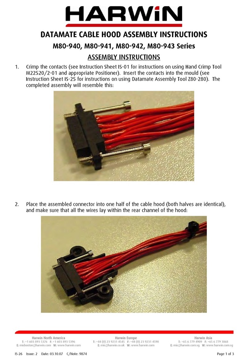
Harwin M80-940 Series User manual

Harwin

Harwin M80-940 Series User manual

Popular Cables And Connectors manuals by other brands

enphase CT-200-SOLID Quick install guide

enphase

enphase CT-200-SOLID Quick install guide

Wayne-Dalton 3995 installation instructions

Wayne-Dalton

Wayne-Dalton 3995 installation instructions

Staubli PV-KST4 UR Series Assembly instructions

Staubli

Staubli PV-KST4 UR Series Assembly instructions

Painless Performance Products 60103 quick start guide

Painless Performance Products

Painless Performance Products 60103 quick start guide

Votronic 1430 Assembly and operating instructions

Votronic

Votronic 1430 Assembly and operating instructions

APP SBS50 Assembly instructions

APP

APP SBS50 Assembly instructions

QPC QSEAL PLUG Customer Assembly Instructions

QPC

QPC QSEAL PLUG Customer Assembly Instructions

Eaton COOPER POWER SERIES installation instructions

Eaton

Eaton COOPER POWER SERIES installation instructions

GoMax Electronics SP-5028E user manual

GoMax Electronics

GoMax Electronics SP-5028E user manual

Gefen DVI Splitter user manual

Gefen

Gefen DVI Splitter user manual

SCHURTER 4795 Series Assembly instruction

SCHURTER

SCHURTER 4795 Series Assembly instruction

OUNEVA VC02-0003 installation guide

OUNEVA

OUNEVA VC02-0003 installation guide

Lenze L-force EYF A Series Mounting instructions

Lenze

Lenze L-force EYF A Series Mounting instructions

Hama 00042005 manual

Hama

Hama 00042005 manual

Lenze EYP A Series Mounting instructions

Lenze

Lenze EYP A Series Mounting instructions

Allen-Bradley ControlLogix 1756-CP3 installation instructions

Allen-Bradley

Allen-Bradley ControlLogix 1756-CP3 installation instructions

AceProAV AcePro-CE33-1 Quick installation guide

AceProAV

AceProAV AcePro-CE33-1 Quick installation guide

HELGI HI0312-V2.0 user manual

HELGI

HELGI HI0312-V2.0 user manual

manuals.online logo
manuals.online logoBrands
  • About & Mission
  • Contact us
  • Privacy Policy
  • Terms and Conditions

Copyright 2025 Manuals.Online. All Rights Reserved.