Weka GUARD User manual

WEKA_Manual_Protector24-05-2016
INSTALLATION MANUAL FOR
WEKA GUARD
WEKA PROTECTOR™
WEKA BOXCOOLERS B.V.
INDUSTRIEWEG 8
NL-2921 LB
KRIMPEN A/D IJSSEL
NETHERLANDS
Telephone +31 180 516 588
Telefax +31 180 516 064
E-mail address info@wekaboxcoolers.com
Website http://www.wekaboxcoolers.com
WEKA GUARD
WEKA PROTECTOR
1

CONTENTS
1.
INTRODUCTION
3
1.1
Warranty and liability
3
1.2
Receipt of goods
3
1.3
Verifying correct installation of Boxcoolers
3
2.
WEKA GUARD
4
2.1
General
4
2.2
Installation
4
2.3
Placement of the WEKA Guard
4
3.
WEKA PROTECTOR
5
3.1
General
5
3.2
Installation
5
3.3
Placement of the WEKA Protector
5
Appendix A WEKA Guard –Schematic connection
Appendix B WEKA Protector –Schematic connection
2

1. INTRODUCTION
• Read this instruction manual before proceeding.
• Important documents in addition to this instruction manual are the order confirmation, the specification
sheet and drawings.
1.1 Warranty and liability
The “General Conditions of Sale of WEKA Boxcooler BV” are applicable. Also refer to the order confirmation
for possible additions.
Please make sure to fill in the supplied “Boxcooler Warranty Registration” form and sent the registration to WEKA
for review and guarantee purposes.
1.2 Receipt of goods
• Upon receipt of goods, please report any damage or discrepancy to WEKA Boxcoolers BV.
• Compare the data on the identification plate, order confirmation and on the drawing.
1.3 Verifying correct installation of Boxcoolers
WEKA Boxcoolers must be mounted galvanically isolated from the ship’s hull. This is to safeguard the lifetime of
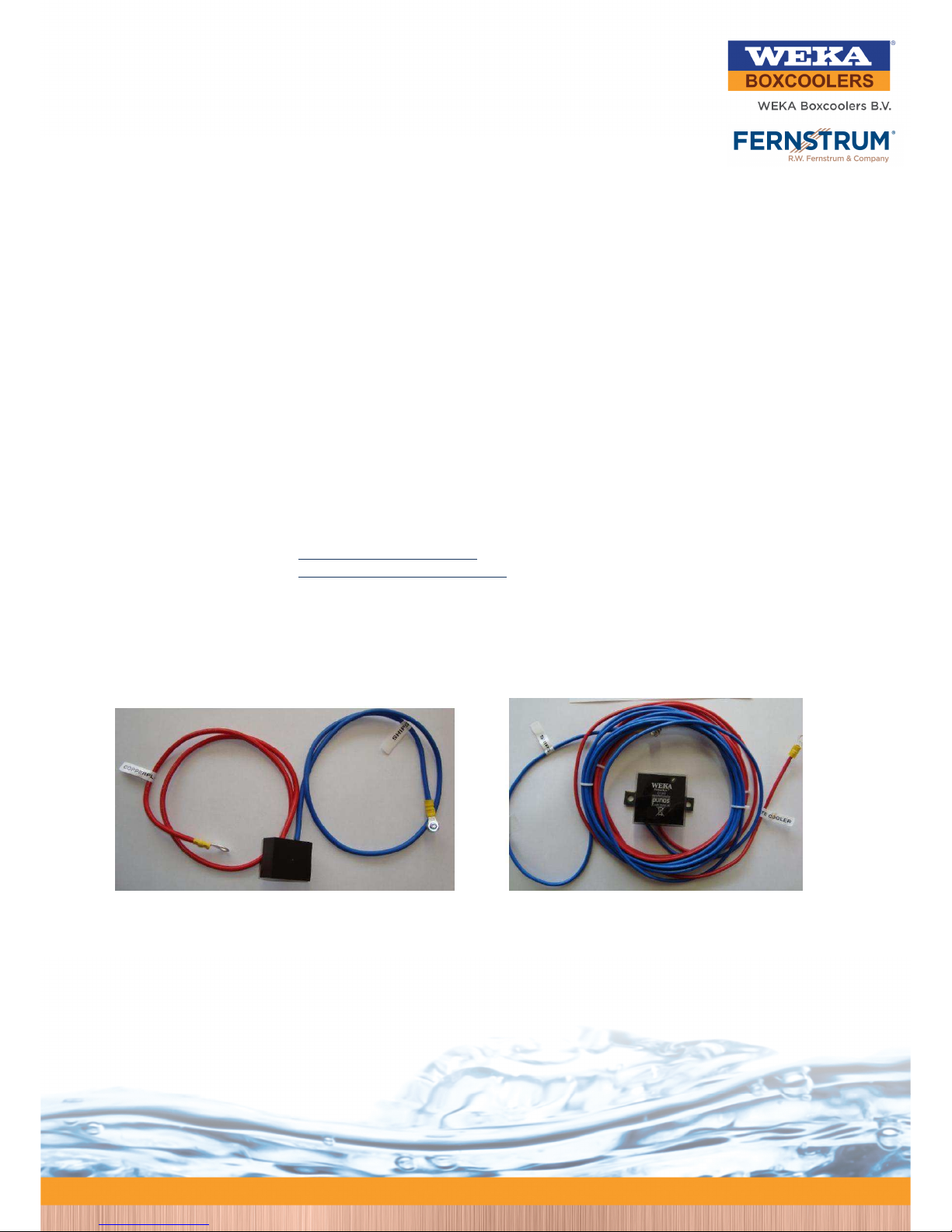
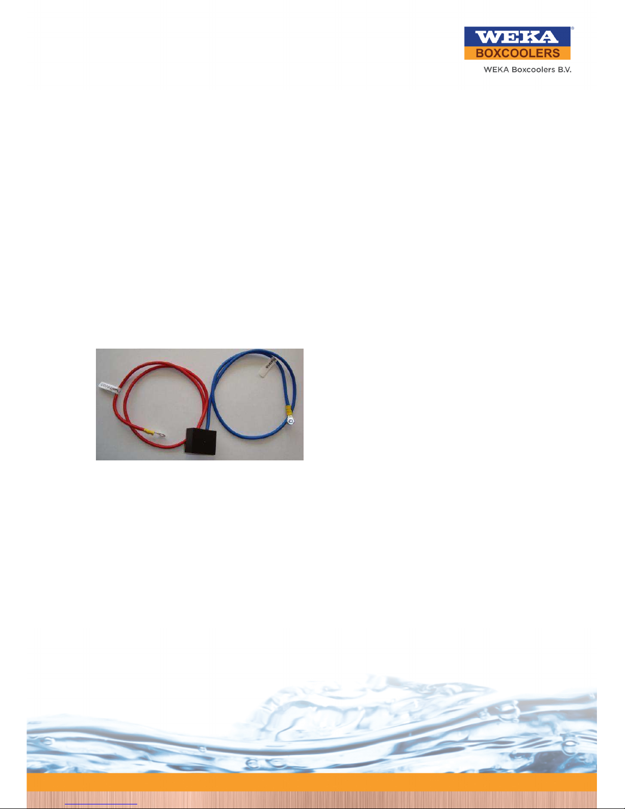
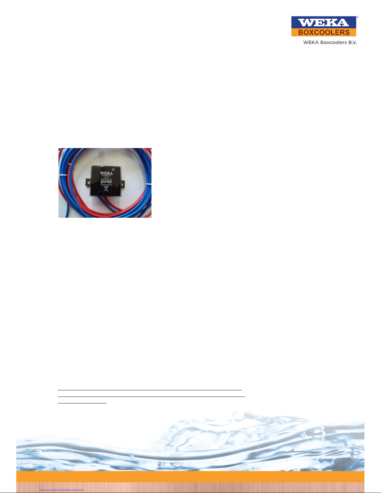
the Boxcoolers, to avoid marine growth on the Boxcoolers and to avoid corrosion. The WEKA Guard and WEKA
Protector are the devices which control and protect the Boxcoolers and the ship from these phenomena, provided
the Boxcoolers are correctly installed.
A few things also mentioned in the “Installation Manual for WEKA Boxcoolers” are highlighted:
1. Make sure the mounting of the Boxcooler is complete – including the bonnet on top of the cooler.
2. The top-plate of the sea-chest (tank top) shall be cleaned from water and obstructing materials.
3. Check the galvanic isolation of the Boxcooler using relevant procedures as below:
Ship is in dry-dock – Boxcooler is not submerged and WEKA Guard is not connected yet
• Measure the resistance Ω(Ohm) between the cooler and the ship’s structure. The resistance must not
be less than 500 Ω(Ohm).
Ship is afloat – Boxcooler is submerged and WEKA Guard is connected
• Measure the resistance between the tube-sheet and a bare piece of the top-plate of the sea-chest.
The potential difference should be approximately 200-350 mV.
Please consult WEKA in case any questions should arise.
3

2. WEKA Guard
2.1 General
In the shipment a device will be included (free of charge) which protects the Boxcooler
from being damaged by welding currents. Welding with Boxcoolers in place must be
performed using the most modern and best available professional welding and grounding
methods.
This device (WEKA Guard) must be connected to the tube-sheet and to the ship’s hull
during the newbuilding process of the ship when the ship-based electrical supply is not yet
available. If not installed, the Boxcooler may suffer severe corrosion due to the welding
currents. Once the ship is completed and due for delivery, the WEKA Guard shall be
replaced by the WEKA Protector, which from this moment on takes over the protection of
the Boxcooler.
2.2 Installation
One WEKA Guard is normally supplied for each Boxcooler.
The WEKA Guard consists of a small box with two wires, a blue and a red one.
The WEKA Guard needs no additional power supply.
The blue cable is connected to the ship’s ground.
The red cable is connected to the tube-sheet of the Boxcooler.
In appendix A, a connection diagram is found for the WEKA
Guard unit.
2.3 Placement of the WEKA Guard
The WEKA Guard shall be placed in a safe area of the ship, in order not to be
damaged during ship’s construction.
4

3. WEKA Protector
3.1 General
WEKA strongly recommends installing one WEKA Protector per Boxcooler. This will
protect the Boxcooler ( to a certain level) from being damaged by ICCP-systems or stray
currents originating from sacrificial anodes. The WEKA Protector is a small device, which is
placed in the vicinity of the Boxcooler to be protected.
3.2 Installation
One WEKA Protector is normally supplied for each Boxcooler.
The WEKA Protector consists of a small box with two wires, a blue and a red. Each
cable is 300 cm of length. The WEKA Protector needs no additional power supply.
The blue cable is connected to the ship’s ground. The red (or brown) cable
is connected to the tube-sheet of the Boxcooler.
In appendix B, a connection diagram is found for the WEKA Protector.
When the WEKA Protector is connected, you must disconnect the WEKA
Guard.
3.3 Placement of the WEKA Protector
The WEKA Protector shall be located near the Boxcoolers in an accessible
position. There are mounting holes around the perimeter of the tube-sheet that
are prepared for screws for attaching the WEKA Protector in a protected and
visible place.
Every two minutes the device will give a flash to show that the protector is working properly.
The WEKA Protector shall be mounted at a sturdy frame, in a dry and well-
protected position, and mounted in such a way that excessive vibrations
are avoided.
NOTE: The WEKA Protector must not be attached to the Boxcooler itself since
the high operating temperature of the Boxcooler may damage the electronics in
the WEKA Protector.
After 5 years the WEKA Protector has to be replaced with a new one.
5

WEKA Guard – Connection scheme
APPENDIX A
When the WEKA Protector unit is installed, the WEKA Guard units should be removed.
One WEKA Guard unit is supplied for each Boxcooler.
6

WEKA Protector – Connection scheme
APPENDIX B
7
This manual suits for next models
1
Table of contents