User manual
TAXI-CHECK – V1.3 - 10
-
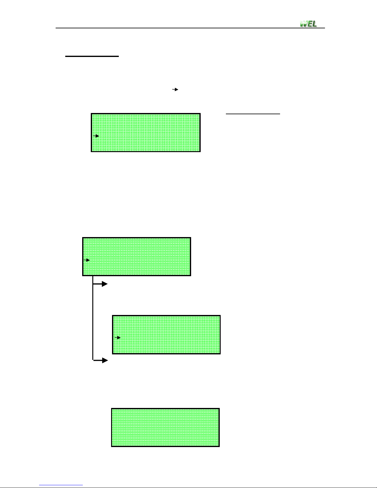
Step 3.
This is the main test screen. The fare value will show n/a since it cannot
be calculated.
Throughout different stages of the test the user may be asked to reduce
the vehicles speed. These speed guidelines should be followed or the test
may be automatically terminated.
When the desired fare has been accumulated on the cab fare meter the
user should press the ENTER key, and advance to step 4.
The test can be manually terminated at any stage by pressing the CLEAR
key, this will return the user to step 5.
When the test is ended the cab driver should decrease vehicle speed until
the wheels are stationary.
Step 4.
Using the DOWN or UP key, select the desired option and press
ENTER. If you want to restart that test without saving the results then
select option 2 restart test), this will return the user to step 1.
Otherwise select option 1 store results) to save test data and
advance to step 5.
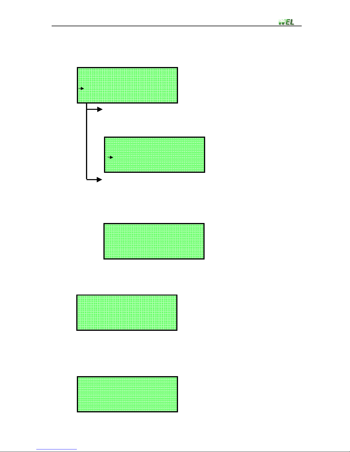
Step .
Since the system only has the ability to save tests as a completed set
the user is given the option of doing multiple tests up to 10) for that
set of tests. To continue with another test select option 1 Start next
test), this will return the user to step 1 allowing the next test to be
setup. If that was the final test for that set then select option 2 End
test set), this will return the user to the main screen. Test data can
then be viewed by following instruction shown in section 3.6.
Test: 1
Speed: 0.0 km/h
Distance: 0.0 m
Fare: n/a
1. Store results
2. Restart test
WHAT TO DO?
1. Start next test
2. End test set