Welch 8890 User manual

OWNER’S MANUAL
FOR
GEM® DIRECT-DRIVE VACUUM PUMP
MODEL 8890
7301 North Central Avenue
Skokie, Illinois 60077
Phone: (847) 676-8800
Fax: (847) 677-8606 (Technical Support)
Fax: (920) 451-4397 (Ordering)
Web-Page: www.welchvacuum.com Printed in U.S.A.
WARNING
Never Block the Exhaust Port. If the exhaust is blocked, pressure
will build-up in the pump with the potential of the pump body
bursting and causing possible injury to personnel in the area.
For outside U.S. and Canada, contact your local
Rietschle Thomas sales office, see back page

2
PLEASE READ BEFORE OPERATION
While reading your manual, please pay close attention to areas labeled WARNINGAND CAUTIONS. The
description of each is found below.
WARNING
Warnings are given where failure to observe instruction
could result in injury or death to people
CAUTION
Cautions are found where failure to observe the instruction should
result in damage to the equipment, associated equipment and process.
These units conform to the SI International system of units of measurement.
The following symbols (with recommendations of IEC1010) of warning will be found on the pump.
Caution - refer to accompanying documents
Caution - risk of electrical shock
Caution - hot surface
WARNING
Motor includes a self reseting thermal cut-out and the pump could restart
without actuation under fault condition.

3
TABLE OF CONTENTS
Warranty ..........................................................................................4
Section 1 – Installation .................................................................. 5
Section 2 – Pump Features and Principles of Operation ............. 8
Section 3 – Specifications .............................................................. 13
Section 4 – Parts List and Exploded Pump View ........................ 16
Section 5 – Operation .................................................................... 18
Section 6 – Maintenance and Troubleshooting ............................19
Section 7 – Repair Service .............................................................22
Section 8 – Accessories & MSDS for Directorr Premium Oil ..... 23

4
WARRANTY
This Welch Rietschle Thomas product is warranted to be free from defects in material and workmanship. This
liability of Welch Rietschle Thomas under this warranty is limited to servicing, adjusting, repairing or replacing any unit
or component part which in the judgment of Welch Rietschle Thomas has not been misused, abused or altered in any
way or damaged by ingestion of foreign material causing impaired performance or rendering it inoperative. Foreign
material includes solids, liquids, corrosive gases and recondensed water or solvent vapor. No other warranties are
expressed or implied. The method of executing this warranty: servicing, adjusting, repairing or replacing shall be at
the discretion of Welch Rietschle Thomas. Vacuum pumps that have been operated within a vacuum system, or other
system, for any period, however short, will be repaired under this warranty rather than replaced.
The warranty is effective for one year from the date of original purchase when:
1. The warranty card has been completed and returned.
2. The product is returned to the factory or other designated service centers, freight prepaid.
3. The product in our judgment is defective through no action or fault of the user.
If the product has become defective through misuse, abuse, alteration or ingestion of foreign materials, repairs will
be billed regardless of the age of the product. In this event, an estimate of the repair costs will be submitted and
authorization of these charges will be required before the product is repaired and returned.

5
Section 1: INSTALLATION
1.1 Introduction
The tradename of this pump is GEM®, because of its suitability for the following laboratory applications:
Evaporators, such as the rotary type
Manifolds for vacuum
This pump also is well suited for use in gas analyzers, continuous gas-flow lasers, general-purpose drying, and
similar uses where a middle-range vacuum level is required. It is a good replacement for diaphragm (membrane)
and water aspirator pumps.
Its unique, patented technology permits pumping at any pressure range from O.1 mm Hg (100 microns) to
atmospheric. At these higher pressures, the pump uses the gas it is pumping to remove heat. Rotary-vane pumps
typically run hotter at these pressures, due to greater frictional forces.
This manual has been written for the care and maintenance of the Model 8890 Vacuum Pump. Take time to read
it carefully, and keep it for future reference. One of the most important aspects of any pump installation is the
precautions taken to prevent condensable vapors from collecting in the pump. Pay particular attention to Section
1-10 for ways to effectively pump condensable vapors.
1.2 Unpacking
Carefully remove the pump from the shipping carton. Keep all paperwork and inspection tags for future
reference. If shipping damage has occurred, a claim must be filed with the carrier immediately; keep the shipping
container for inspection by the carrier.
1.3 Pump Mounting
Rubber bumpers are supplied with the pump base. They isolate noise and eliminate creeping. For more rigid
mounting requirements the pump base can be the bumper holes to put the mounting bolts through. Refer to
Section 3 – Specifications for mounting hold location dimensions.
1.4 Pump Location
The pump should be located in a clean and well-ventilated area and adequate space should be provided wherever
possible for routine maintenance such as oil changes. For best performance, the pump should be located as
closely as possible to its system. Determining factors for pump locations should include length and size of
connections, the number of bends, and the type of exhaust connections.
1.5 Exhaust Provisions
Exhaust connections will be determined by the type of system to be exhausted and desired cleanliness of the air
surrounding the pump. Under normal pumping conditions nothing more than the optional exhaust filter will be
necessary. Refer to Section 9 – Accessories for various exhaust filters available. Where extreme exhaust
conditions are encountered, it is best to pipe the filter exhaust out of the building. The pump’s exhaust connection
is a threaded port, ¾-20, located opposite the inlet port on top of the oil reservoir. It will accept the Model 1417
Exhaust Filter, which is furnished with the pump, or can be used with the Model 1396J Hose Nipple, for 7/16 in.
ID hose.

6
WARNING
Never block or impede air flow from the exhaust port. High pressure
can build up within the oil reservoir if the exhaust flow is blocked.
Check frequently, especially if exhaust is piped out of the building.
1.6 Electric Power
Compare the pump motor rating, printed on a label on the side of the motor, to the power source, to be sure they
agree in voltage, phase, and frequency. Pump installation must comply with local electrical codes which dictate
appropriate protection devices such as fuses or circuit breakers. We strongly suggest that you learn the location
and operation of the circuit breaker or fuse protecting the electrical outlet for the pump so that you can react
quickly in the event of an emergency.
The vacuum pump motor is factory wired to for 115 V for models which operate from 60 Hz, and
220 V for models which operate from 50 Hz. The motor wiring can easily be changed for operation at a voltage
different than that set at the factory. Follow the motor wiring schematic diagrams in Section 3-2 – Motor Power
Specifications and Special Features.
Identification Symbols:
CAUTION
Only a qualified technician should attempt motor rewiring. Motor lead wires can
be accessed by removing the four screws on the top lid of the motor junction box.
1.7 Vacuum Connections
The pump inlet is equipped with a hose barb nipple for connection of 3/8 in. ID hose. It is located next to the
pump handle.
The choice of connections and fittings can have a very marked effect on the pumping speed at the vacuum
chamber. Any connection placed between the pump and the chamber creates an impedance to the flow of gas.
This is particularly true at low pressures in the millitorr range where the gas flow is substantially molecular in
character. The gas flow is then dependent upon the kinetic activity of the molecules to bring it to the pump
intake.
The conductance of a tube is proportional to the cube of its diameter and inversely proportional to its length.
Therefore, connecting lines should be as large in diameter and as short in length as practical. For best results the
connection tube should be at least as large as the diameter of the pump intake. To avoid a large reduction in
pumping speed at the vacuum chamber, the conductance of the line must be considerably greater than the speed of
the pump.
1.8 Vacuum Gauges
The type of vacuum gauge to be used in a system is determined largely by the pressure range to be measured. A
thermocouple gauge or a dial-type gauge, is recommended for measuring pressures in the range produced by this
pump. See Section 9 – Accessories.

7
1.9 Vacuum Pump Oil
CAUTION
The vacuum pump is shipped without oil inside to prevent
possible spillage during shipment. Oil must be added prior to use.
Remove the fill plug located on the top of the oil case and add the oil supplied in a bottle packaged with each
pump. Both the fill and drain plugs have knurled edge and a center slot for easy turning either by hand or with a
screwdriver.
Be sure the pump is filled with oil to the level indicated on the oil fill window. When additional oil is required, use
only DIRECTORR® Premium Vacuum Pump Oil; pump performance is not guaranteed with other brands of oil.
Do not overfill the pump, and be sure to replace the oil fill plug.
After the pump has been running for at least 15 minutes, check the oil level again. The oil level should be
maintained between the “add” mark and the “full” mark on the oil level window while the pumpis operating. Do
not overfill; excess oil tends to be splashed out the pump exhaust. The ideal level is four “ribs” down from the
top of the oil case, or about ½ in. below the “full” mark.
1.10 Pumping Condensable Vapors
Liquids can collect in a vacuum pump by either being ingested or sucked directly into the pump, or by its vapors
condensing in the pump.
If the application requires pumping directly on a liquid, or on samples whose surface contain large amounts of
liquid, the initial pumping may draw some of this liquid directly into the pump. The use of a liquid trap is
recommended. A plastic flask of sufficient size is often adequate. Please it nearest the source of the liquid being
pumped. Inlet and outlet connections should be make at or near the to prevent any of the trapped liquid from
being drawn out by the pump.
To prevent condensable vapors from condensing in the vacuum pump, several measures should be taken. These
include:
A. Control of the pressure in the vacuum system. Not all vacuum systems need to, or should be, operated at the
lowest pressure possible for the pump. Rotary evaporators, for example, depend on a pressure setpoint high
enough to prevent the distillate collected from revaporiazing. If revaporized, it can easily recondense in the
pump.
Use of a bleed valve and pressure gauge is recommended.
Use the Cat. No. 1423 Vacuum Manifold Valve/Gauge Kit.
B. Trap condensable vapors in a cold trap. If the pressure of the system must be set at or near the ultimate
pressure of the pump, or if the vapor load is high, use a cold trap is recommended. It should be placed away
from sources of heat, such as the pump, for maximum efficiency.
Several types of cold traps are available. They include:
1) Dry Ice/Alcohol Slurry Traps which maintain a temperature of about –75 C.
2) Liquid Nitrogen Traps which maintain a temperature of about –100 C.
3) Refrigerated Traps which typically maintain temperatures between about – 25 to –80 C.
See Section 9 – Accessories for a selection of these traps. Consult a handbook for the melting temperatures
of the liquids being pumped. Some very heavy vapor loads may require these of two traps in series. Once the
trap is installed and charged, wait for it to reach its minimum temperature before turning on the vacuum pump.
The condensed vapor must be removed from the trap on a frequent basis to prevent revaporization via
sublimation, and to allow the trap to work at its peak efficiency.

8
Section 2: PUMP FEATURES AND PRINCIPLES OF OPERATION
2.1 General Description
The Model 8890 Vacuum Pump is a two-stage, direct-drive gerotor pump featuring:
a. Capacity of 28 Liters/Minute (1 CFM).
b. Ultimate pressure of 0.1 mm Hg (100 microns)
c. Intake isolation valve available on certain models
d. Continuous operation at intake pressures from 100 microns too atmospheric.
For clarity, the modular vacuum pump assembly is referred to as the pump in this section.
2.2 Principles of Vacuum Pump Operation
The main purpose of a vacuum pump is to reduce the pressure in a vessel or a closed system. The degree of
pressure reduction is dependent upon the requirements of the application and the type of vacuum pump employed.
Mechanical, rotary, oil-sealed pump operation is described in this section because of its similarities to the
pumping action of this gerotor gear pump.
Pressure reduction in a closed system is accomplished by repeatedly removing a portion of the original volume of
gas contained in the system. Removal is performed by the action of the rotating elements of the pump which
cause a given space to be successively enlarged and diminished. Figure 2-1 illustrates a section through a typical
stage of a rotary vane pump. Note that this figure is not intended to illustrate the internal components of a gerotor
pump such as the Model 8890; its purpose is to illustrate the general operating principles of vacuum pumps.
The rotary action of the pump creates a hollow space or chamber (1) which expands as the pump rotates. As the
chamber expands, the pressure in the chamber decreases. As a result, gas is drawn into the chamber due to the
difference in pressure between the chamber and the inlet (4) to the chamber. (The inlet is the only place where
gas can flow into the chamber.)
Figure 2.1
Typical Rotary Vane Pump,
Schematic Diagram
Once the vane (3) moves past the inlet (4), it seals the inlet against the chamber (1), and the gas becomes trapped
between the vanes (2 and 3). The chamber (1) formed by the enclosed space between the vanes then begins to
decrease in volume as the rotor revolves, compressing the gas. The pressure of the compressed gas becomes
greater than atmospheric pressure. When the vane (2) moves past the exhaust port (5) the compressed gas in the
chamber is forced out through the exhaust port.
This expansion/compression cycle constitutes one complete cycle of pump operation. This cycle is repeated as the
vane (2) passes the intake port and seals it against the atmosphere. Therefore, two pump cycles are performed
during each revolution of the pump rotor.

9
2.3 Effects of Continued Pressure Reduction
The quantity of gas in the vessel (6) is reduced with each evacuation cycle. The gas remaining in the vessel
expands to fill the vessel and consequently with each cycle the pressure in the vessel is reduced. This is a
manifestation of Boyle’s law which states that for a constant temperature, the volume of a body of gas is inversely
proportional to its pressure, i.e. if the volume is enlarged the pressure must be reduced.
As the amount of gas in the vessel is steadily diminished, its pressure is correspondingly reduced. The action of
the pump must therefore compress a successively smaller quantity of gas with each cycle to something greater
than atmospheric pressure in order to expel it from the pump.
At the beginning of an evacuation sequence, the compression ration is very small. In the first cycle of operation
the pump draws in a volume of gas at atmospheric pressure and expels it at approximately atmospheric pressure.
In contrast, at ultimate pressure, a pump draws in gas at (for example) 100 millitorr and must compress it to more
than 760,000 millitorr (atmospheric pressure) in order to expel it from the pump. Since the exhaust valve is
generally spring loaded to provide a good seal, the pressure required to open it is somewhat greater than
atmospheric pressure. Therefore, at an ultimate pressure of 100 millitorr (1 x 10 Torr) the compression ration
performed by the pump is approximately 10,000 to 1.
2.4 Ultimate Pressure
As described previously, a quantity of gas is removed from the system with each cycle of the pump. Therefore,
the pressure of the gas remaining in the system is reduced with each pump cycle. Since the pump can remove
only a small portion of the gas with each pump cycle, it is obvious that this method of evacuation can never
completely remove all the gas in the vessel. In addition, all the components of the system contain minute sources
of gas leakage which are impossible to seal completely against atmospheric pressure. Outgassing of materials
within the system provide additional sources of gas.
As a result, after prolonged pumping, a state of equilibrium is reached in which the gas introduced from all the
leakage sources is balanced by the ability of the pump to remove gas from the system. This state of equilibrium is
referred to as the ultimate pressure, or blankoff pressure, of the pump and its system. No matter how much
additional pumping time is provided, no further reduction in system pressure will be accomplished once ultimate
pressure is attained.
2.5 The Gerotor Vacuum Pump
The Model 8890 Vacuum Pump uses patented technology, (U.S Patent No. 4,519,755) developed by Welch
Vacuum, employing two gerotor stages to pump gases. Each gerotor stage consists of an inner rotor and an outer
roto Figure 2-2 is a cutaway view of a single gerotor pump showing the inner and outer rotors. There is a one-
tooth differential between the two rotors; the inner rotor has one less tooth than the outer rotor. The inside
diameter of the outer rotor is somewhat larger than the outside diameter of the inner rotor.
Figure 2.2
Gerotor Pump Chamber,
Schematic Diagram

10
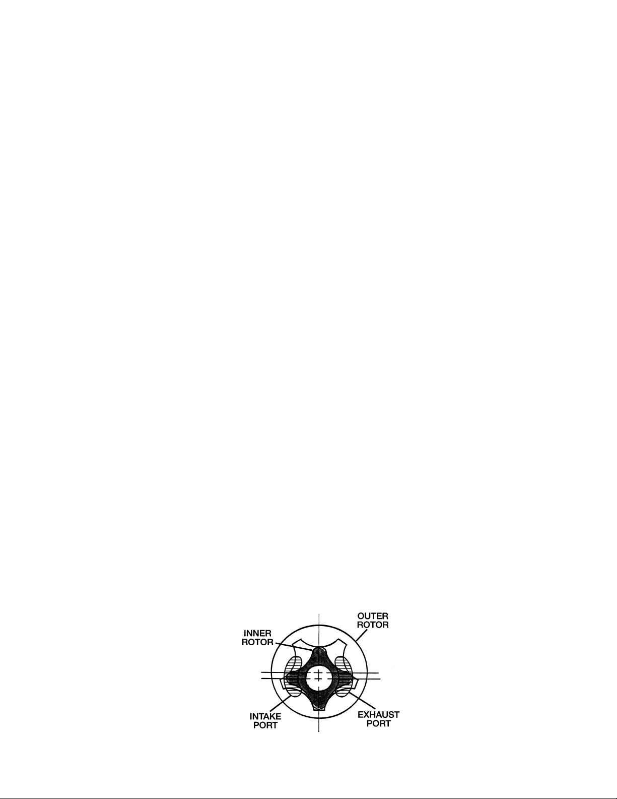
The outer rotor is held in place by a housing and is free to rotate within the housing. The pump shaft drives the
inner rotor, which in turn drives the outer rotor in the same direction, but at a slower speed.
In a gerotor pump, the pumping chamber is created between the inner and outer rotors. The boundaries of the
chamber are defined by the two contact areas where the teeth of the inner rotor meet the teeth of the outer rotor.
As the two rotors revolve, the resulting speed differential between the inner and outer rotors creates a pumping
chamber which is constantly moving. The chamber expands and contracts as the rotors turn. Inlet and outlet
ports are placed to allow gas to enter and exit the pumping chamber at the proper points. These ports, in
conjunction with the movement of the chamber, produce pumping action. A film of oil acts as a sealant and
lubricant between the two rotors, allowing pumping down to relatively low pressure levels. Because the relative
velocity between the inner and outer rotors is low, there is minimal wear of the rotating parts. As a result, the
gerotor pump is very reliable.
2.6 Pump Mechanism Description
The Model 8890 Vacuum Pump incorporates two separate in-line gerotor stages with interconnecting ports.
Relative to each other, the intake stage is at high pressure and the exhaust stage is at low pressure. Each stage
contains a two piece gerotor assembly consisting of an inner drive rotor and an outer driven rotor; the two stages
are enclosed in a common gerotor housing. The shaft turns the drive rotor which then drives the driven rotor.
Each stage has an exhaust valve with a backer valve; the backer valve prevents excessive exhaust valve travel.
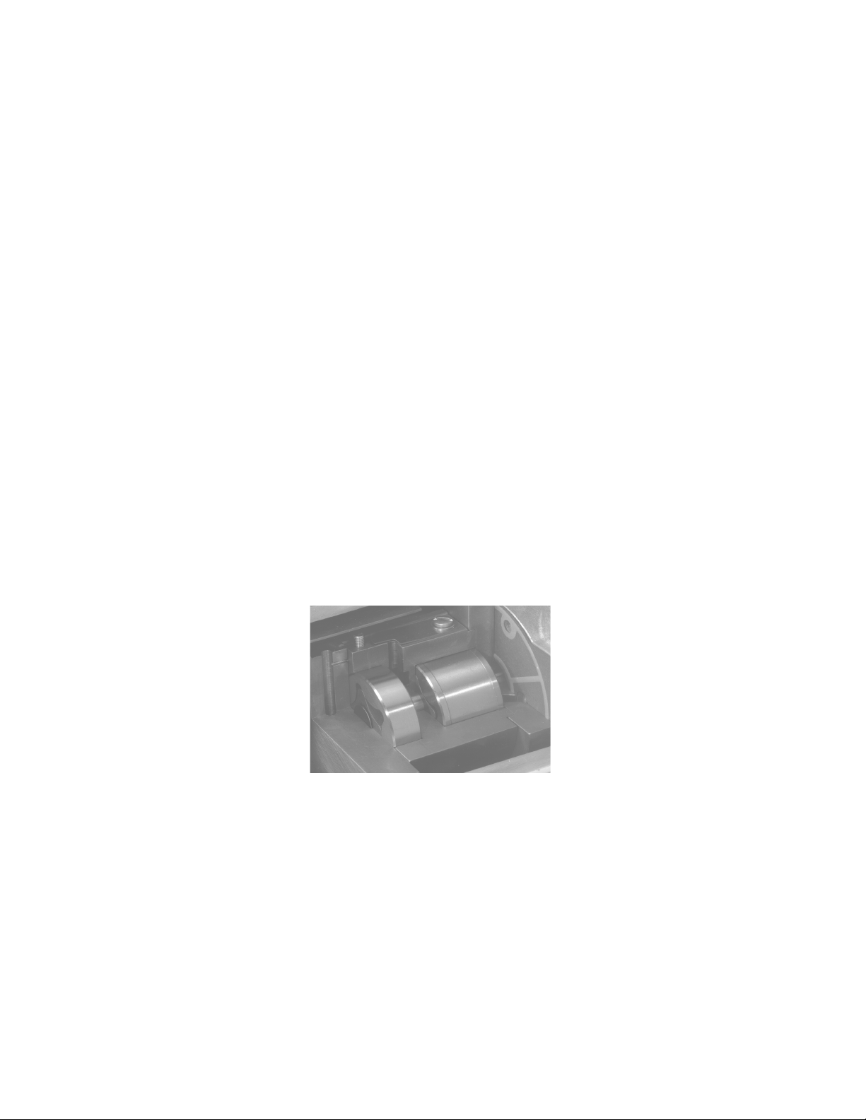
The intake gerotor stage, which is the larger of the two stages, is closest to the driven end of the shaft. The intake
gerotor is larger in volume and its size determines the pumping rate of the pump. See Figure 2-3.
Gas from the system being evacuated flows into the inlet of the intake gerotor and is compressed in the gerotor
chamber. At the beginning of a pump down, the pressure of the compressed gas is sufficient to force the bypass
valve open, so most of the compressed gas is forced out the bypass valve and is vented to the atmosphere. As the
evaculation of the system continues, the pressure of the compressed gas eventually reaches a point where it is not
sufficient to force the bypass valve open.
Figure 2.3
Two Stage Gerotor Pump,
Cutaway View
At this point, all of the compressed gas instead flows from the intake gerotor into the inlet of the exhaust gerotor,
is compressed again, and with the help of the lubricating oil, pushes the exhaust valve open. From there, the
compressed gas flows out the pump’s exhaust port and is vented to the atmosphere. Both the bypass valve and the
exhaust valve have backer valves to provide extra opening resistance.
A small orifice is located in the exhaust stage. The function of this orifice is to reduce the noise level of the
pump. The orifice allows a small amount of air at atmospheric pressure to enter the gas being discharged from the
exhaust stage. This reduces the pressure differential between the atmosphere and the gas leaving the pump,
thereby reducing noise from the pump exhaust. When the pump motor is shut off while the pump is still
connected to a vacuum, the orifice vents the pump, preventing oil suckback.
The pump is mounted inside an oil case which is a reservoir for the oil that lubricates the pump. The motor shaft
drives the pump shaft via an electric motor coupling. There is a coupling body on the end of each shaft; a
coupling spider between the two coupling bodies transfers the power from the motor shaft to the pump shaft.

11
2.7 Pump Lubrication
To ensure efficient operation and proper maintenance, and to minimize noise and oil vapors, it is important to use
the correct type and quantity of oil. DIRECTORR® Premium Vacuum Pump Oil has been especially developed
to have the proper viscosity, low vapor pressure, and chemical stability needed to produce peak pumping
efficiency. The ultimate vacuum guarantee on this pump applies only when DIRECTORR® Premium oil is used.
Each pump is supplied with a bottle of oil sufficient for filling. Additional oil is available. See Section 9 –
Accessories for sizes available.
Oil is fed into the pumping chamber by the differential pressures created by the rotation of the pump. Oil metered
into the pump through a narrow opening is sufficient to lubricate and seal the moving parts, permitting the
pumping of gas at relatively low pressure levels.
2.8 Intake Isolation Valve Models
Cat. No. 8890A-55, 8890C-56 and 8890C-57 Vacuum Pumps have a solenoid-operated isolation valve in the
pump intake. When power to the pump is turned off, this valve closes automatically, maintaining vacuum in the
system being evacuated, and vents the inside of the pump to atmospheric pressure. The solenoid is wired to the
pump’s ON/OFF switch. When the pump is turned on, the spring-loaded solenoid plunger is pulled down, but the
isolation valve remains held against the pump intake by the pressure differential between that of the pump and
chamber. After a very short time, the pressure of the pump equals the pressure in the chamber, at which time the
isolation valve drops due to its own weight, opening then take of the pump to allow gas to flow into the pump
again. Figure 2.4 illustrates the components of the valve.
Figure 2.4
Intake Isolation Valve,
Cutaway View
2.9 Exhaust Filter
Any oil-sealed vacuum pump tends to discharge oil mist from its exhaust port when the pump operates under high
flow conditions, such as when the pump’s intake is at or near atmospheric pressure. Typically, oil mist in the
form of a white puff of “smoke” can be seen from the exhaust port when no filter is used. Once the vacuum level
and the corresponding air flow through the pump are reduced, very little, if any, oil mist will be emitted. An
exhaust filter is recommended when the pump operates at relatively high intake pressure for any length of time.
Oil droplets entrained in the pump’s exhaust are removed by the exhaust filter element. Use of an exhaust filter
typically reduces or baffles pump noise as well. Exhaust filters are sometimes referred to as Oil Mist Eliminators,
or as Smoke Eliminators. A Model 8817 Exhaust Filter is furnished with each pump. See Section 10-Accessories
for a selection of additional filters available.

12
Section 3: SPECIFICATIONS
Table 3.1 Pump Specifications
* Partial measurement based upon the American Vacuum Society Test
Procedure No. AVS 5.1-1963 using a trapped McLeod Gauge.
ledoM0988
segatSforebmuN2
tnemecalpsiDriAerF
zH06@).nim/L(MFC
zH05@h/3m).nim/L(
)13(1.1
65.1)62(
)rabm(rroT*erusserPetamitlUdeetnarauG)3.1(1-01x0.1
ABdleveLdnuoS85
deepSpmuP/rotoM
zH06@mpr
zH05@mpr
0543
5782
warDtnerruCrotoM roV511@A0.3
V032@A5.1
rewopesroHrotoM4/1
)strauq(sretilyticapaCliO)84.0(54.0
elppindedaerhtTPN4/1,noitcennoCekatnIbraBesoH"8/3
deriuqeR.D.IgnibuT"8/3
noitcennoCtsuahxEdedaerht02-4/3
).gK(.sblthgieWpmuP)1.11(5.42
noisnemiDllarevO
)mc(sehcniL
)mc(sehcniW
)mc(sehcniH
)8.63(5.41
)0.31(1.5
)3.12(4.8
).gK(.sblthgieWgnippihS)8.11(62
noisnemiDnotraCgnippihS
)mc(sehcniL
)mc(sehcniW
)mc(sehcniH
)4.93(5.51
)8.71(0.7
)4.52(0.01
.oN.taCretliFtsuahxE7141
.oN.taCtnemelEelbaecalpeRretliFL7141
.oN.taCtiKriapeR20-K0988
.oN.taCmuimerPRROTCERID,epyTliO)retiL1(11-P5998

13
Figure 3.1 Pumping Speed Curve Figure 3.2 Pump Down Curve
of Model 8890 Vacuum Pump of Model 8890 Vacuum Pump
Figure 3.3 Dimensional Drawings, Model 8890 Vacuum Pump

14
Table 3.2 Motor Power Specifications and Special Features, Model 8890
Cat. No. Voltage Freq. Phase Factory Special Feature
Wired For
8890A 115/230 60 1 115 V
8890A-55 115/230 60 1 115 V Isolation Valve
8890A-85 115/230 60 1 115 V Prepared for use with Fomblin YL-VAC-06/6,
Isolation Valve
8890C-01 115/230 60 1 230 V North American Plug
8890C-02 115/230 50 1 220 V European Schuko Plug
8890C-56 115/230 60 1 230 V N. American Plug, Iso. Valve
8890C-57 115/230 50 1 220 V Euro. Plug, Iso. Valve
Models can be easily rewired to operate at either the low (115 V) or high (220-230V) voltage. When changing
the factory wiring, replace the line cord plug with one suitable for the voltage connection which meets the local
electrical codes. Figure 3-4 shows the electrical schematic for low voltage; Figure 3-5 shows it for high voltage.
This applies to Franklin Electric Motors, Model No. 1603007401, and 1603007402, for both 50 and 60 Hz
operation.
Figure 3.4 Electrical Wiring Figure 3.5 Electrical Wiring
Wiring Diagram, Low Voltage Schematic Diagram, High Voltage

15
PARTS LIST 8890A VACUUM PUMP
ITEM QTY PC. NO. A* B* DESCRIPTION
01 2 62-1037 Screw, Fillisterhead, #8-32x7/16
02 1 61-2370 Window Holder
03 1 61-2229A Window Glass
04 1 66-0304 1 O-Ring, Fluoroelast. #127
05 1 61-2413 Drain Plug
06 1 61-2158A O-Ring, Fluoroelast. #111
07 1 61-2230B Oil Case
08 1 61-2130A 1 O-Ring, Fluoroelast. #115
09 1 61-2372 Filler Plug
10 8 2-00-6712 Screw, Sockethead, #10-32x3/4
11 14 2-62-0793 Lock Washer #10
12 3 62-0003 Screw, Sockethead, #10-32x3
13 1 61-1189B End Plate
14 1 61-1186B Cover Baffle
15 1 61-0007A Exhast Rotor Set
16 4 4-21-3006 Dowel Pin 1/8x3/8
17 1 61-1182C Gerotor Housing
18 2 2-10-1604 Screw, Binderhead, #8-32x1/4
19 2 2-68-5632 Washer #8
20 1 61-1120A Thrust Disk
21 1 61-9398A Valve Cover Spacer
22 2 61-1121A Key
23 1 61-1123A 1 Intake Valve
24 1 61-1128A 2 Backer Valve
25 1 61-1124B Shaft
26 1 61-0006A Intake Rotor Set
27 1 2-10-5607 Screw, Roundhead, #8-32x7/16
28 1 61-1179A 1 O-Ring, Fluoroelast. #034
29 1 41-2962 1 Lip Seal, 3/8”
31 1 61-1184C Wear Plate
ITEM QTY PC. NO. A* B* DESCRIPTION
32 1 61-1119B 1 Gasket
33 1 61-1318 Mounting Plate
33* 1 61-1321 Mounting Plate
34 1 61-9429 Screw, 10-32x3/16 with O-ring
36 1 61-2221A Intake Nipple
37 3 2-00-6708 Screw, Sockethead, #10-32x1/2
38 1 61-2313 Adapter Plate for Franklin Motor
38 1 61-2314 Adapter Plate for Emerson Motor
39 2 4-21-5010 Dowel Pin, 3/16”x5/8”
40 2 41-2693 Coupling Body
41 4 2-00-6716 Screw, Sockethead, #10-32x1
42 1 41-2694 1 Coupling Rubber
43 1 61-2377 Handle
44 2 2-61-1165 Washer 1/4
45 2 2-01-6112 Screw, Sockethead, 1/4-20x3/4
46 1 61-9479A 1 Drip Pad
47 1 61-2039C Motor Assy 1/4 HP, 60Hz, Franklin
47 1 61-2040C Motor Assy 1/4 HP, 50Hz, Franklin
47 1 61-2007C Motor Assy 1/4 HP, 60Hz, Emerson
47 1 61-2025C Motor Assy 1/4 HP, 50Hz, Emerson
48 4 61-2123A 4 Rubber Bumper
49 1 61-2120C Pump Base
50 4 2-00-6812 Screw, Sockethead, #10-32x5/8
53* 1 61-2139A Disk Assembly, Isolator Valve
54* 1 61-2216A Plunger
55* 1 61-2155A 1 O-Ring, Fluoroelast. #020
56* 1 61-2212A Adapter, Isolator Valve
57* 2 2-00-6410 Screw, Sockethead, #6-32x5/8
58* 1 61-2308 ISO Operator Assembly w/O-Ring
** 1 1417 Exhaust Filter
A*: MAJOR REPAIR KIT CAT # N/A
B*: MINOR REPAIR KIT CAT # 8890K-02
* Parts used in 8890A-55 Pump only
** Part supplied with the Pump but not shown
67-1480
Sheet 1 of 2
Rev. 2 6/04

16
Section 5: OPERATION
5.1 Starting Procedure
Before using the pump for the first time, it is a good idea to spend a few minutes inspecting the pump and its
electrical and vacuum connections. Review Section 1 – Installation as required. Check the AZ power outlet to be
sure that it is the same voltage and phase as the pump motor. Connect the pump’s power cord to the power outlet.
Check the pump’s oil level to be sure it is correct.
Close off the pump intake and run the pump at blankoff for a few minutes. The gurgling noise should go away
after a few seconds of running; it is caused by the high volume of air that flows through the pump is first turned
on. If the gurgling noise does not stop, check the oil level to see if it is low, and check the pump intake fitting to
be sure that it is tight. Once proper pump operation has been verified, the pump intake can be opened to the
vacuum system.
After running the pump for a few minutes, check the oil level again. If the level is too high or too low, stop the
pump and add or remove oil as needed. Stop the pump and vent it to the atmosphere before adjusting the pump
fluid level.
Before starting the pump when connected to the vacuum system, check all vacuum connections.
5.2 High Pressure Operation
The Model 8890 pump is designed to be most efficient when operated at or near its ultimate blankoff pressure.
When operated at elevated pressures, the exhaust filter provided should be used. When operated at high pressures
for long periods of time, this filter will saturate quickly, and puffs of “smoke” will be seen around it. Replace the
filter with a new one, or replace with the Model 1417 Filter with replaceable cartridge. See Section 10 –
Accessories.
5.3 Shutdown Procedures
A few simple precautions are necessary before performing a pump shutdown. If a gauge is connected to the
system, first isolate the gauge, then turn off the power to the pump and open the system to the atmosphere.
NOTE
The intake isolation valve, in models equipped with this feature, will automatically close
when power to the pump is turned off. This will maintain vacuum in the system (if the
pump remains connected to the rest of the system) and will vent the pump to atmosphere.
If the pump is disconnected from the system for any length of time, cover the pump intake with a rubber stopper or
other suitable cover to protect the pump against contamination and loose particles. If the exhaust port is open, that
should be covered also. If the pump oil is contaminated and the pump is going to be stored for a prolonged period,
the oil should be changed before the pump is stored. Even if a pump is stored for a long period with oil initially in
good condition, check the oil when the pump is restarted, and change the oil if necessary.

17
Section 6: MAINTENANCE AND TROUBLESHOOTING
6.1 Vacuum Problems
Inability to attain sufficient vacuum in a system is usually due to leakage, contamination, or unusual outgassing. A
system must be thoroughly clean and free from leaks to operate efficiently. If the system is found to be clean and
leak-free, but vacuum problems still exist, the pump should be checked. A simple way to test the pump is to
measure its ultimate pressure capability. This can be done by disconnecting the pump from the rest of the system
and connecting a pressure gauge directly to the pump intake. (Be sure to seal the pump intake from the
atmosphere.) The gauge can be any type that is suitable for the pressure levels expected. Run the pump until the
gauge indicates no further reduction in pressure, and compare the pressure reading to the pump’s ultimate pressure
rating.
If the pump meets its ultimate pressure specifications only when disconnected from the rest of the system, the
fault must be elsewhere in the system. If the pump’s ultimate pressure is unusually high, the pump may be badly
contaminated, low on oil, or mechanically defective. However, if the pressure is only slightly higher than the
pump’s guaranteed pressure, an oil change may be all that is needed to bring performance up to specifications.
Be sure to use only DIRECTORR® Premium Oil in the Model 8905 Vacuum Pump; the ultimate pressure
guarantee does not apply if other types of oil are used.
The most common cause of efficiency loss in a vacuum pump is contamination of the oil, which is usually caused
by foreign particles and/or condensed vapors. The condensate emulsifies with the oil, and when the oil is
recirculated, the condensate evaporates. The resulting vapor then reduces the ultimate vacuum attainable in the
system.
Some foreign particles and vapors from sludges with the oil. The presence of sludge in the oil impair its sealing
and lubricating properties, and eventually could cause pump seizure. Therefore, periodic oil changes are
necessary to maintain efficient operation of the system. The interval at which oil changes are required is different
for each system; experience will help you determine the proper interval for your system and process.
6.2 Oil Change
The best time to change the oil is when the pump is warm and the oil is less viscous. Before attempting
an oil change, the pump must be disconnected from the power outlet.
WARNING
The drain oil is hot and can cause burns. Operating temperature of the oil
is typically 140 degrees Fahrenheit or higher. Avoid skin contact with the oil.
Oil Removal: Drain the oil into a container by removing the black plastic drain plug located below and to the left
of the oil sight glass. The container should hold at least one quart of oil. The pump may be tilted to remove
residual oil out of the oil reservoir.
Oil fill: Replace the oil drain plug, remove the black plastic oil fill plug located on the top of the oil reservoir.
Fill the pump with vacuum oil until the level reaches the Full mark as seen from the oil sight glass. Do not
overfill the pump. The excess oil tends to splash out of the exhaust. Replace the oil fill plug. Check the oil level
again after the pump warms up to its normal operating temperature. Add or remove oil as needed. It is normal for
the oil level to change upon initial start up.
NOTE
When filling the pump with oil, be sure to use only DIRECTORR® Premium
Oil.The ultimate pressure quarantee applies only if this oil is used.

18
6.3 Shaft Seal Replacement
When the shaft seal in the mounting plate shows signs of excessive oil leakage, it should be replaced. Before
attempting replacement of the seal, the pump must be disconnected from the vacuum system and from the power
outlet. New lip seal (P/N 41-2962) and new gasket (61-1119B) or seal replacement kit (Cat. No. 8890K-03)
should be available before attempting repair.
1. Drain Oil by opening the drain plug. The pump may be tilted to remove residual oil out of the oil case.
2. Separate Base from the pump by removing four socket head screws 10-32 x 5/8.
3. Separate the Pump from the Motor Assembly by removing four socket head screws 10-32x1 from
the motor adapter plate. For 8890A-55, the isolator valve coil should be slipped off by removing nut, name
plate and large washer from valve projecting from the inside of the mounting plate. Set aside the motor
assembly with isolator coil placed next to it.
4. Remove Oil Case from the pump by placing it on its mounting plate side and unscrew four socket head
screws 10-32x3/4.
5. Remove Coupling from the pump shaft by loosening the setscrew. Separate pump module from the
mounting plate by unscrewing three socket head screws 10-32x1/2 and three split lock washers. Discard
the gasket.
6. Push out Lip Seal out of the wear plate with a blunt edge of a screw-driver blade. Discard the lip seal.
Older models will have lip seal installed in the mounting plate.
7. Install New Shaft Seal with flat side of the seal toward the motor. Use a little oil on the lip seal outside
periphery. The seal is located 0.09 from the coupling end inside the bore. Seal assembly tool 61-2172A
used to install it.
8. Place the Pump Module on a table with shaft up. Slide shaft insertion tool 61-2170A over the shaft
end and place the new gasket over the modular assembly.
9. Moisten the Lip Seal, shaft and the tool with oil prior to the assembly. Slip the mounting plate over the
shaft of the modular pump.
10. Adjust Gasket in proper angular location and then tighten gradually 3 screws 10-32x1/2 with lock
washers.
11. Assemble Coupling Body to pump shaft all the way to the shaft shoulder and tighten the setscrew.
12. Attach Oil Case to the mounting plate using four socket head screws 10-32x3/4 with 4 lock washers.
Tighten screws gradually.
13. Insert two dowel pins to the mounting plate and put the coupling spider in place.
14. Attach Motor Assembly to the mounting plate using four socket head screws 10-32x1 with lock
washers. For Model 8890A-55, watch for wires from the isolator valve coil to be placed in groove of
motor adapter plate during assembly. After carefully fitting all parts together cross tighten the four
screws gradually, then attach the coil to the isolator valve mechanism by first slipping on the coil houlder
and then the coil with name plate. Tighten the coil nut (name plate should turn freely).
15. Attach Base to the mounting plate by means of four socket head screws 10-32x5/8 long.
16. Finally pump is filled with DIRECTORR® Premium Oil and is ready to be inspected for its
performance.

19
TROUBLESHOOTING
6.4 Trouble Shooting Guide

20
Section7: REPAIR SERVICE
7.1 Repair Kits
Minor repairs to the pump can usually be performed in the field. Minor repair kits contain those parts which can
be easily replaced, are most likely to wear, and involve only minor repair. Parts constituting the internal
mechanism of the pump which would require complete pump disassembly for replacement are not included.
7.2 Major Factory Repair
With proper care, this pump will give many years of service. The basic working parts of vacuum pumps are
machined to close tolerances and require assembly on fixtures, with special tools, by mechanics who are highly
skilled at this work. Should major repairs involving the pump mechanism become necessary, we strongly
recommend that the pump be returned to the factory for repair.
Welch Rietschle Thomas maintains complete repair facilities in the United States. These facilities are well
equipped and staffed with experts to insure prompt reconditioning of all returned pumps. Broken, worn, scored or
corroded parts are replaced with new parts, and the pump is thoroughly evaluated and tested to determine that it
meets the performance requirements.
7.3 Minor Repair Kit For Model 8890 Vacuum Pumps
A minor repair kit, Cat. No. 8890K-02, is available for the Model 8890 Vacuum Pump. This kit contains a group
of parts that can be replaced in the field. Table 7-1 lists the contents of the minor repair kit. Refer to Figure 4-1
Exploded View Diagram. this should be used as a guide for disassembly and assembly.
Table 7.1 Minor Repair Kit for Model 8890 Vacuum Pump, Parts List
Part No. Description Quantity Where Used
61-2158A O-Ring, #110 1 Oil Drain Plug
61-1123A Intake Valve 1 Pump Module
61-1128A Backer Valve 2 Pump Module
61-1122A Exhaust Valve 1 Older Models
61-1178A Silencer 1 Older Models
61-1119B Oil Case Gasket 1 Mounting Plate
61-2130A Bumper Rubber 4 Base
41-2694 Coupling Spider 1 Motor/Pump
41-2962 Lip Seal 1 Wear Plate
61-2130A O-Ring, #115 1 Oil Fill & Intake Older Models
61-2162A O-Ring, #015 (iso. valve models) 1 Isolation Valve
61-2155A O-Ring, #020 (iso. valve models) 1 Isolation Valve
67-0729 Instruction Manual 1 —
61-1174A Installation Tool 1 Lip Seal
61-1175A Insertion Tool 1 Lip Seal
61-2231 Tetraseal, #127 (New S/N 1025 & Up) 1 Sight Glass Window
61-1179A O-ring, #034 1 Gas Ballast
61-9479A Drip Pad 1 Pump
Table of contents
Other Welch Power Pump manuals
Popular Power Pump manuals by other brands

Greenlee
Greenlee 940m3 SERIES instruction manual

Viking pump
Viking pump 823 Technical & service manual

Greenlee
Greenlee 940 instruction manual

MULTIQUIP
MULTIQUIP QP305SLT Operation and parts manual

STA-RITE
STA-RITE SL Series owner's manual

BLACKMER
BLACKMER NPH2F Installation, operation and maintenance instructions