Weldability Sif ProtecoReclenz User manual

Operating instructions
Type
ProtecoReclenz
ProtectoReclenzTwin
Weldability sif
Peters House, The Orbital Centre
Icknield Way, Letchworth Garden City
Hertfordshire
SG6 1ET
Tel.: +44 (0) 845 862 2620
Fax: +44 (0) 800 970 7757
E-Mail: sales@weldability-sif.com
www.weldability-sif.com

ProtectoReclenz - 2 -
Table of contents
1 Drawing / Description of components ..................................................................................................3
2 Introduction ..........................................................................................................................................5
3 Intended use / Functional principle Weldability ProtectoReclenz ........................................................6
4 Safety instructions................................................................................................................................6
5 Initial operations...................................................................................................................................8
5.1 Mounting of suction arm ................................................................................................................................ 8
5.2 Electrical connection ...................................................................................................................................... 9
6 Explanation of the controls...................................................................................................................9
7 Maintenance and service...................................................................................................................10
7.1 Cleaning of filter cartridge ........................................................................................................................... 10
7.2 Compressed air supply ................................................................................................................................. 11
7.3 Emptying of dust collector bin ..................................................................................................................... 11
7.4 Change of filter cartridge.............................................................................................................................. 12
8 Fault removal and fault diagnosis ......................................................................................................13
9 Handling of waste ..............................................................................................................................13
10 Technical data................................................................................................................................14
11 List of spare parts...........................................................................................................................15
12 Declaration of conformity Weldability ProtectoReclenz.................................................................16

ProtectoReclenz - 3 -
1 Drawing / Description of components
ProtectoReclenz,
Pos.1
Pos.2
Pos.3
Pos.4
Pos.5
Pos.6
Pos.7
Pos.8
Pos.9
Pos.10
Pos.11
Pos.12
Pos.13
Pos.14
Pos.15
Pos.16
Pos.17
Power switch
Operating hour counter
Operating status lamp: green
Volume flow control lamp: red
Signal horn
Suction arm with suction hood or
connecting piece
Lid
Hand grip
Cartridge box
Cartridge access door
Filter cartridge
Cartridge guide
Cartridge bracket
Fastening screw for filter cartridge
Drawer box
Drawer access door
Dust collecting bin
Pos.18
Pos.19
Pos.20
Pos.21
Pos.22
Pos.23
Pos.24
Pos.25
Pos.26
Pos.27
Pos.28
Pos.29
Pos.30
Pos.31
Pos.32
Pos.33
Pos.34
Lifting device
Fastening screw for dust collecting bin
Fan housing
Fan access door
Cleaning access door
Silencing housing with air outlet grid
Cap nut for cartridge door
Caster with brake
Caster
Screw for mounting of suction arm
Spring washer for mounting of suction arm
Turning flange
Cap nut for fan access door
Mains cable with plug
Dust collecting bag
Wrench for the lifting device
Toggle clamp

ProtectoReclenz - 4 -
ProtectoReclenzTwin
Pos.1
Pos.2
Pos.3
Pos.4
Pos.5
Pos.6
Pos.7
Pos.8
Pos.9
Pos.10
Pos.11
Pos.12
Pos.13
Pos.14
Pos.15
Pos.16
Pos.17
Power switch
Operating hour counter
Operating status lamp: green
Volume flow control lamp: red
Signal horn
Suction arm with suction hood or
connecting piece
Lid
Hand grip
Cartridge box
Cartridge access door
Filter cartridge
Cartridge guide
Cartridge bracket
Fastening screw for filter cartridge
Drawer box
Drawer access door
Dust collecting bin
Pos.18
Pos.19
Pos.20
Pos.21
Pos.22
Pos.23
Pos.24
Pos.25
Pos.26
Pos.27
Pos.28
Pos.29
Pos.30
Pos.31
Pos.32
Pos.33
Pos.34
Lifting device
Fastening screw for dust collecting bin
Fan housing
Fan access door
Cleaning access door
Silencing housing with air outlet grid
Cap nut for cartridge door
Caster with brake
Caster
Screw for mounting of suction arm
Spring washer for mounting of suction arm
Turning flange
Cap nut for fan access door
Mains cable with plug
Dust collecting bag
Wrench for the lifting device
Toggle clamp

ProtectoReclenz - 5 -
2 Introduction
In recent years, a special type of welding fume extraction systems has become an ever more
prominent factor: Filtering of welding fumes and return of the filtered air into the workshop area.
This shows that the issue of environmental consideration has turned for the better for all concerned.
There never has been any doubt about the existence of harmful fumes at welding sites. However,
type of fumes depends on the particular welding process and welding technique. One can generally
differentiate between gases and fumes. The fumes could also be referred to as fine dust.
Investigating them under the microscope, we are able to see particles of a size that will pass
through the respiratory tract deep into our lungs. The size of these particles is a small as 0.001 mm
or even less.
Ventilation is the general approach to improve the conditions at the relevant work positions.
Generally, this is effected by continuously exchanging the air in the workshop, i.e. the total air
volume is exchanged at a high rate. This method will reduce the concentration of harmful particles
within the hall to a great extent, however, it will improve the air within the breathing range of the
individual welder to a negligible portion only.
This also applies to overhead suction systems, i.e. the installation of large extraction hoods
overhead of welding places. Here again the heavily polluted air passes upwards through the
breathing range of the welder. Extraction and/or filtering take place overhead and outside the range
of the welder. A point-attack extraction of the welding fumes right at their place of origin is far more
effective than room ventilation or overhead extraction. Both capital investment for on-the-spot fume
extraction as well as the operating costs for such systems are far below those of the previous
conventional solutions.
Environmental and work protection measures are prerequisite for the successful application of
advanced welding technologies, aside from the optimisation of such welding processes. In view of
increased awareness of the problems involved and in compliance with pertinent legal directives, the
danger potential for personnel and environment must be considered at an early stage and it must
be minimised using appropriate technical solutions.

ProtectoReclenz - 6 -
3 Intended use / Functional principle Weldability – ProtectoReclenz
The filter unit is especially used to extract and filter fumes and dusts. The filter unit is among other
things suited to separate fumes generated when working on steels and complies with the highest
welding fumes class “W3” according to DIN EN ISO 15012-1.
An improper use of the device and of live components can cause damages of
single elements up to dangers to life and limb!
The unit must not be used to extract welding fumes containing oil, explosive dusts and
gases, hybrid mixes, burning or glowing substances, gases, water etc. Furthermore, the
unit must not be used in explosive zones (If in doubt, contact the manufacturer!).
The polluted air is extracted via the suction hood (or a specific suction head) and directed into the
suction arm (or suction hose) and into the filter unit. Here, the particles are collected on the surface
of the filter cartridge. The clean air passes the fan and returns into the room via the exhaust grid
Pos.31).
Caution:
As soon as the accumulated dust particles on the filter cartridge yield a maximum resistance to the
air flow, the integrated electronic control will illuminate the red lamp of the air flow volume control
(Pos.4) and the signal horn (Pos.5) sounds up.
The filter cake is removed by manually by directing the air jet of a compressed air pistol onto the
filter area.
(Refer to chapter 7.1 ‘Cleaning of filter cartridge)
The removed filter cake is gathered in the dust collecting bin from which it can be taken for final
waste handling. (Refer to chapter 7.3 ‘Emptying of the dust collector bin’)
4 Safety instructions
The following basic safety measures must be observed to prevent of electric shocks, injury or fire
when using electrical devices:
•Read and follow the instructions listed below before using the filter systems !
•Store the operating and service instructions in a secure and readily accessible space !
•Do not employ the unit for the extraction of easily combustible or explosive gases!
•Do not employ the unit for the extraction of aggressive media !
•Do not employ the unit for setting it in explosive zones, e.g. zone 0, zone 1, zone 2, zone
20, zone 21, zone 22!
•Do not employ the unit for sucking off burning or glowing materials, e.g. cigarettes,
matches, metallic types of dust and/or splinters, paper, cleaning cloths, etc.!
•Do not employ the unit for sucking off burning and/or inflammatory materials, e.g. oils
and/or oil mist, fats, parting agent (e.g. silicone spray), cleaning agent, etc.!

ProtectoReclenz - 7 -
•Do not employ the unit for the sucking up of liquids of any kind !
•Do not employ the unit for extraction of any organic matters without the written permission
of the manufacturer !
•Protect the connecting lead from heat, wetness, oils and sharp edges !
Confirm the correct voltage. (Refer to the unit type plate)
•Use only original Weldability spare parts !
•Do not operate the unit without a filter cartridge installed !
•Pull the mains plug before opening the unit !
•The exhaust gird must not be obstructed or blocked in any way!
•Always take care that the unit stands secured and that the caster brakes are set !
•Pull the mains plug when cleaning or servicing the unit, when exchanging any parts or when
changing machine settings for a different function !
•The filter cartridges cannot be regenerated for repeated use !
•The filter cartridges must be disposed of according to pertinent legislation and directives !
•At regular intervals inspect the mains supply lead for signs of damage !
•The unit must not be used when there is any damage or irregularity at the mains supply
lead !
•Use only dry and oil-free compressed air with pressure ratings from minimum 3 bar to 4 bar
maximum.
•Reposition the suction arm during welding operations, if possible by exploiting the thermal
flow of the welding fumes
•The maximum permissible distance of 25 cm to the welding point should not be exceeded.
•Do not use the filter unit when any one or more components of the system are defective,
missing or damaged. In any one of these instances contact the Weldability Service
Department: Phone: +44 (0) 845 862 2620
•When extracting carcinogenic welding fumes as from the processing of nickel or chrome
alloys, the requirements of the directives on clean air of the German TRGS 560 ‘Return of
process air when working with carcinogenic media’ must be observed. (And/or the
equivalent national directives for the respective user.) The suction unit ProtectoReclenz has
been checked and approved by the Institute for Work Safety (BGIA) under the certification
number xxxxxx. This certification is part of the operating instructions.
•Further information regarding the TRGS 560 can be obtained from the
‘BGIA - Berufsgenossenschaftliches Institut für Arbeitssicherheit’
(Institute for work safety of the employers’ liability insurances) at
D-53754 Sankt Augustin, Germany.

ProtectoReclenz - 8 -
5 Initial operations
The filter unit is delivered in a state ready to be plugged to the mains supply.
Prior do using the machine, the extraction/suction elements, e.g. the suction arm and appropriate
optional accessories, must be mounted or installed.
5.1 Mounting of suction arm
Attach the suction element (Pos.6) e.g. the suction arm or the connecting piece and clamping
flange (Pos.29), screws (Pos.27) and spring washers (Pos.28).
Caution:
The connecting element must move/turn freely !

5.2 Electrical connection
•Connect the filter unit to the mains supply. (Observe the information on the type plate!)
•When you switch the unit on for the first time, make sure that the fan rotor turns in the
required direction. This can be detected in case of a weak extraction performance. An
adhesive label is fixed within the fan housing for a visual inspection. In case of connections
of 400 V or 500 V, it is possible that the set rotary field is incorrect and needs to be
changed.
Attention:
The warning label „Disconnect the unit from the mains supply before opening the housing“ is only to be
ignored in exactly this case. Open the door when the unit is switched off, but do not reach into the fan
housing at any moment. Now switch the unit switch switch on for a short time and then switch it out.
The fan starts operating slightly and it is now possible to compare the sense of rotation to the label.
Wait until the fan has stopped to shut the door with the help of the cap nuts.
If you have any further questions, please contact our after-sales team: Phone: +44 (0) 845 862 2620.
Please note:
It is possible that the sense or rotation has to be checked every time the device is connected to another
mains connection.
Only authorized electricians are allowed to carry out tasks in the electrical field!
6 Explanation of the controls
Pos.1 The main switch switches the filter unit on or off.
Pos.2 The operating hour counter starts to count as soon as the filter unit will be switch on.
Pos.3 The operating status lamp shows if the filter unit will be switch on.
Pos.4 + 5 The red volume control lamp (Pos.4) illuminates and the signal horn (Pos.5) sounds,
when the suction power is no longer adequate. Now the filter inserts must be cleaned
manually (Refer to chapter 7.4: ”Change of filter cartridge”).

7 Maintenance and service
The accumulation of extracted particles on the filter cartridge will eventually lead to a reduction of
the suction / extraction performance.
The rate of accumulation and thereby the degrading of the filter cartridge (Pos.11) is monitored
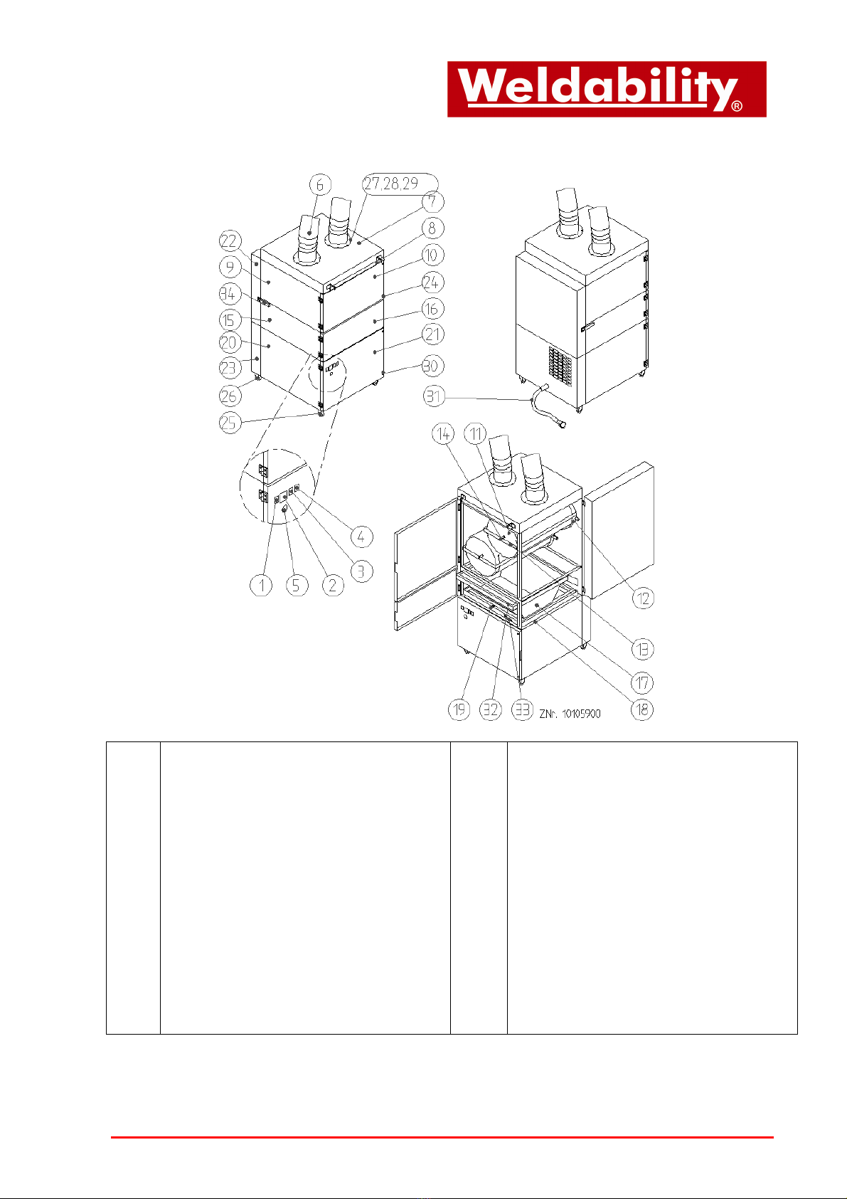
electronically. In order to maintain the designed suction performance, the filter cartridge must be
cleaned when the red volume control lamp (Pos.4) illuminates and/or the signal horn (Pos.5)
sounds. (Refer to chapter 7.1: ”Cleaning of filter cartridge / Manual cleaning”)
The accumulated dust particles are blown off the filter by applying compressed air from the clean
side. The released filter cake will drop into the dust collecting bin (Pos.17). (Refer to chapter 7.3:
”Emptying of dust collector bin”)
The useful service life of the filter cartridge greatly depends on the operational environment. For this
reason, it cannot be predicted.
If the operating pressure of the filter unit should not be achieved after cleaning the filter cartridge,
the cartridge must be replaced. (Refer to chapter 7.4: ”Change of filter cartridge”)
Caution:
Stop the operation of the filter unit when changing the filter cartridge.
Exchange of the filter cartridge and the disposal of the element may be executed only in amply
ventilated environments and when using an appropriate protective respiratory mask!
We recommend to use a respiratory mask to DIN EN 141/143 - Protection class P3. It is also
recommended to use appropriate protective gloves.
Dispose of the filters according to the legal regulations. The polluted filter elements must be put in
an appropriate container (e.g. PE bag), bags are available as an option (see list of spare parts)! We
recommand to stockpile some PE bags in time.
The task of changing the filter elements should be executed by trained personnel only!
7.1 Cleaning of filter cartridge
When the red volume control lamp (Pos.4) illuminates and the signal horn (Pos.5) sounds, the filter
cartridge must be cleaned according to the following procedure:
•Disconnect the filter unit from the mains supply (Pull the plug) !
•Close the throttling flap at the suction hood.
•The front doors of the housing (pos.10 + 16 + 21) have to be closed.
•Open the cleaning access door (Pos.22) by releasing the overcentre lock (Pos.34).
•Evenly apply the air jet from the compressed air pistol (available as an option) to the filter
cartridge (Pos.11). (Refer to chapter 6.2. “ Compressed air supply”)
•Apply the air jet for ca. 5 – 10 minutes.
•Close the cleaning access door (Pos.22) and secure it with the overcentre lock (Pos.34).
•Open the throttling flap at the suction hood.
•Connect the filter unit to the mains supply.
•(Observe the information on the type plate!)
Caution:
Without the compressed air supply, the filter cartridge will be clogged, and its performance will
degrade rapidly. The unit will indicate a fault (Filter clogged/full) !
Do not manually shake or wash the filter element as this will damage the filter medium, and the
harmful waste particles will be returned into the workshop's atmosphere !

7.2 Compressed air supply
A suitable compressed air supply must be proved to ensure the correct function of the suction unit.
•The compressed air must be dry and oil-free.
•External air supply via an approved pressure hose and at an operating pressure from 3 bar
minimum to 4 bar maximum.
Caution:
Without the compressed air supply, the filter cartridge will be clogged, and its performance will
degrade rapidly. The unit will indicate a fault (Filter clogged/full) !
7.3 Emptying of dust collector bin
After a certain number of operating hours, the duct collector bin (Pos.17) shall be cleaned. The
schedule depends on the mass of accumulated dust. The dust collector bin is not allowed to be filled
with more than 25% quantity.
•Disconnect the unit from the mains supply (Pull the plug).
•Open the drawer access door (Pos.16).
•Lower the lifting device (Pos.18) by turning the fastening screw (Pos.19) downward.
•Pull out the dust collector bin (Pos.17).
•The dust collecting bag (Pos.32) with the accumulated dust take and lock.
•The accumulated dust must be store/dispose off the matter according to pertinent directives.
•A new plastic bag into the dust collecting bag insert, so that the opening of the bag is inverted
over the edge of the dust collecting drawer.
•Push the dust collector bin (Pos.17) all the way back into the drawer box (Pos.15).
•Raise the lifting device (Pos.18) by turning the fastening screw (Pos.19) until the dust
collector bin (Pos.17) sits tight and leak-free.
(Also check for possible damage of the sealing gasket under the cartridge box (Pos.9).)
•Close the drawer access door (Pos.16).
•Connect the filter unit to the mains supply.
(Observe the information on the type plate!)
Caution:
Exchange of the filter cartridge and the disposal of the element may be executed only in amply
ventilated environments and when using an appropriate protective respiratory mask !
We recommend to use a respiratory mask to DIN EN 141/143 - Protection class P3.
The task of changing the filter elements should be executed by trained personnel only !

7.4 Change of filter cartridge
The change of the filter cartridge is necessary as soon as the filter alarm is returning in short
intervals, in spite of well cleaning. Before changing the filter cartridge has to be cleaned. (refer to
chapter 7.1: “cleaning of filter cartridge”).
•Disconnect the filter unit from the mains supply.
•Before starting the changing prepare an appropriate container.
Attention:
The polluted filter elements must be put in an appropriate container (e.g. PE bag), bags are
available as an option (see list of spare parts)! We recommand to stockpile some PE bags in time.
•Release the cap nut (Pos.24) and open the cartridge access door (Pos.10).
•Release the fastening screw (Pos.14) of the cartridge bracket (Pos.13), and stülp the PE-
bag about the the cartridge bracket and the filter cartridge.
•Release the cartridge bracket (pos. 13) at one upper side and swivel it to the side.
Withdraw it with the filter cartridge (Pos.11). Finally withdraw the cartridge bracket out oft he
PE bag, taking care of a low dust release.
•Push the new filter cartridge into the cartridge guide (Pos.12). Take care of a correct
position of the sealing.
Caution:
Only use original Weldability replacement filter cartridges !
•Tighten the fastening screw (Pos.14) of the cartridge bracket (Pos.13).
•Close the cartridge access door (Pos.10) and tighten the cap nut (Pos.24).
•Connect the filter unit to the mains supply.
Caution:
Exchange of the filter cartridge and the disposal of the element may be executed only in amply
ventilated environments and when using an appropriate protective respiratory mask !
We recommend to use a respiratory mask to DIN EN 141/143 - Protection class P3.
The task of changing the filter elements should be executed by trained personnel only !
Disposal of the old filter cartridge according to pertinent directives !

8 Fault removal and fault diagnosis
Fault Cause Elimination of defect
Suction hose is not connected. Connect the suction hose.
Suction hose is damaged. Replace the suction hose.
Suction trajectory is clogged. Check the suction trajectory
and eliminate the defect.
No suction capacity
(fumes are not sucked
off).
Cleaned air outlet is covered. Check the cleaned air outlet
and eliminate the defect.
Filter element saturated. Replace the filter pack,
dispose of the old filter
according to the requirements!
Damage at the suction hose. Replace the suction hose.
Suction hose or suction arm not
correctly connected.
Check the connection of the
suction hose or suction arm
and connect it.
Motor turns into wrong direction. Change the rotating field of the
mains tapping point.
Cleaned air outlet is narrowed. Check the cleaned air outlet
and eliminate the defect.
Suction capacity too low
(fumes are hardly
sucked off).
Suction trajectory is narrowed. Check the suction trajectory
and eliminate the defect.
Connector power supply is not or
wrongly plugged.
Check/plug the connector
power supply.
Device does not start.
No power on socket. Check the power line and
eliminate the defect.
9 Handling of waste
To ensure an efficient and orderly operation of your ProtectoReclenz extraction unit and for
compliance with the correct disposal of the collected dust media, we offer the following services:
•A list of such speciality companies in Germany can be provided on your request at no extra
cost.
•Our customer services by phone or Fax
Feel free to contact our Service Department where you will be assisted on a round-the-clock basis:
Phone: +44 (0) 845 862 2620 Fax: +44 (0) 800 970 7757

10 Technical data
Caution:
Refer to the data on the type plate !
Filter unit
ProtectoReclenz
ProtectoReclenz
Twin
Electrical power supply V 230 / 400 / 500 230 / 400 / 500
Current Ph 1 / 3 / 3 1 / 3 / 3
Frequency Hz 50 50
Motor rating kW 1,1 2,2 / 2,4 / 2,2
Air volume flow, max. m³/h 1210 2220
Air volume flow, min. m³/h 700 1160
Vacuum, max. Pa 2900 2600
Protection class IP 54
ISO - class F
Control voltage V 24
Operating time % 100
Width x Depth x Height mm 665 x 820 x 1365
665 x 914 x 1797
Weight kg 165 200
Number of suction arms 1 2
Type of filter Filter cartridge
Filter area of filter cartridge m² 10 20 (2x 10)
Rate of extraction/separation % >99
Mode of cleaning manual
Noise level
(Measured acc. to DIN 45635 T1 in 1m distance
from the surface of the unit in a clear area at the
maximum air flow volume.)
dB(A) 72 74
Compressed air External
Pressure, min. bar 3
Pressure, max. bar 4
Compressed air supply dry / oil-free

11 List of spare parts
Designation: Article-No.:
PE bag for the disposal of filter cartridges (4 units) 10030250
Motor 1.1 kW 230V 1Ph 50 Hz 20000004
Motor 1.1 kW 400V 3 Ph 50 Hz 20000007
Motor 1.1 kW 500V 1Ph 50 Hz 961025
Motor 2,2 kW 230V 1Ph 50 Hz 200421150222303
Motor 2,4 kW 400V 3 Ph 50 Hz 20000011
Motor 2,2 kW 500V 3 Ph 50 Hz 200421150225002
Filter cartridge, filter surface 10m² 10025
Spare hose, suction arm 2 m 101925
Spare hose, suction arm 3 m 101926
Spare hose, suction arm 4 m 101927

12 Declaration of conformity Weldability – ProtectoReclenz
Weldability sif
Peters House, The Orbital Centre
Icknield Way, Letchworth Garden City
Hertfordshire
SG6 1ET
Tel.: +44 (0) 845 862 2620 Fax: +44 (0) 800 970 7757
E-Mail: sales@weldability-sif.com www.weldability-sif.com
We herewith declare in sole responsibility that the before mentioned product, starting from machine
No.: 9000010011001, conforms to the following standards:
Directives on machine building: 2006/42/EG
Electromagnetic compatibility: 2004/108/EG
Directives on printing device: 97/23/EG
Directives on low voltage: 2006/95/EG
Applied harmonised standards:
- DIN EN 349
- DIN EN 983
- DIN EN 12100 part 1 and 2
- DIN EN 60204 part 1
- DIN EN ISO 13857
- DIN EN ISO 14121
plus further national standards and specifications:
- DIN 45635 Teil 1
- DIN EN ISO 15012-1
This declaration will become void if changes are effected to the suction and filter systems which
were not agreed upon in writing by the manufacturer.
Authorized representative for the technical documentation: Technical department, Weldabiility
This manual suits for next models
1
Table of contents
Popular Water Filtration System manuals by other brands

EcoWater
EcoWater ESM11CE owner's manual

Philips
Philips Saeco BRITA INTENZA+ user manual

Veolia
Veolia Hydrotech Drumfilter HDF - 16/20V- Value... Operation and maintenance manual

Monzana
Monzana DBWC001 instructions

Aquasana
Aquasana Rhino Well 1 Water with UV owner's manual

Kinetico
Kinetico SuperSoft Installation instructions and user manual