6
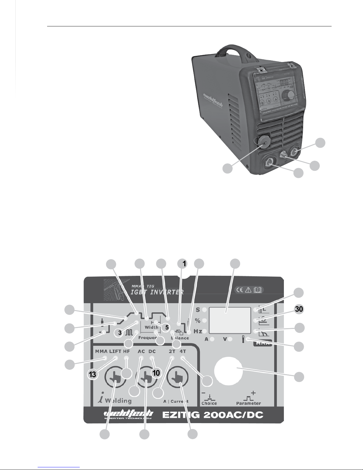
TIG 2T/4T Trigger Control (5 - 7)
In2TModethetriggerispulledandheldontoacti-
vate the welding circuit, when the trigger is released,
the welding circuit stops. 4T is known as ’latching’
mode. The trigger is pulled once and released to ac-
tivate the welding circuit, pulled and released again
to stop the welding circuit. This function is useful
for longer welds as the trigger is not required to be
heldoncontinuously.TheEZITIG200AC/DCalsohas
more advanced current controls that can be used in
4T mode.
AC/DC Output Modes (8 - 10)
DC (Direct Current)Welding Output is suitable for
TIGweldingferrous(ironbased)metalssuchasmild
steel and stainless steel, copper and titanium.
TIG welding reactive metals such as Aluminium,
Magnesium and Zinc requires AC (alternating cur-
rent) output.When reactive metals are exposed to
air they form an oxide layer that insulates the base
metal and prevents welding current owing, it also
contaminatestheweldpool.Reversecurrentowis
requiredtobreakthrough/cleanothisoxidelayer
so that welding can take place, while the current
ow during the positive cycle does the majority of
the heating of the weld pool area.
TIG HF/ Lift Ignition Modes (12 - 13)
ForTIGweldingprocess,contactofthetorchtung-
sten to the workpiece will cause contamination of
the tungsten and the workpiece that will adversely
aecttheweldquality,especiallywhenthetungsten
iselectricallyenergised.HF(highfrequency)ignition
sends a pulse of high energy electricity through the
torch system that is capable of ‘jumping’ between
the tungsten and the workpiece, ensuring arc start-
ing without any contact between the tungsten and
workpiece.The disadvantage of HF ignition is that
the high energy electrical pulse creates signicant
electrical and radio signal interference, which limits
its use around sensitive electronic equipment such
as computers.
Lift TIG ignition is a compromise that minimises
tungsten contamination while eliminating the elec-
tricalinterferenceofHFstartsystems.Liftarcstart-
ing works by lightly resting the tungsten on the work
Controls Explained piece, activating the torch trigger signal and then
liftingthetungsteno.Thecontrolcircuitwillsense
when the tungsten is removed from the work piece
and send a low powered pulse of electricity through
thetungstenthatwillcausetheTIGarctoinitiate.Be-
cause the tungsten is not ‘live’ when it is in contact
with the work, contamination is minimised.
Pre Flow (15)
Pre ow controls the period shielding gas will ow
for when the torch is triggered before the arc starts.
This purges the work area of atmospheric gas which
could contaminate the weld before the weld starts.
Start Current Setting (16)
Available in 4T trigger mode only, sets a welding cur-
rent5-100%ofthemain weldingcurrentactivated
when the trigger is held on, to ‘latch’ the trigger
before the main weld current is started. Once the
trigger is released, the current will go through the
upslope(17)periodifitisset,tothemainwelding
current(18).
Up Slope (17)
When the trigger is activated, the welding current
will increase gradually over the time selected up to
thesetmainweldingcurrent(18).
Down Slope (20)
When the trigger is released, the welding current will
reduce gradually over the time selected down to 0.
This allows the operator to complete the weld with-
out leaving a ‘crater’ at the end of the weld pool.
End Current Setting (21)
Available in 4T trigger mode only, sets a welding cur-
rent5-100%ofthemain weldingcurrentactivated
when the trigger is held on, to ‘unlatch’ the trigger
beforetheweldisnished.Ifdownslope(20)isset,
the current will go through the downslope period
before going to the end current set. When the trig-
ger is released, the arc will stop.
Post Flow Gas (22)
Controls the period of time the shielding gas contin-
ues to ow for after the arc is stopped. This protects