Welkin P2 User manual

Welkin P2 User manual

Incorrect use or operation of this product may result in personal injury and property damage, and Shuxiying
Technology (Chengdu) Co., Ltd assumes no responsibility for this. This product is not suitable for
usebyminors. Please usethis product after readingthis product manual in detail.
Shuxiying Technology (Chengdu) Co. and Ltd do not bear any liability for personal injury and
propertydamage causedbythe following reasons:
1Use this product in case of alcohol, fatigue and other poor physical conditions or poor mental state;
2The product is not assembled or usedin accordancewith the correctinstructions in this manual;
3Damage causedby replacingor modifying this product byyourself;
4The UAVitself hasproblems suchas natural wear andtear,damage to the line, andso on;
5The UAVis in an abnormal state and is still forcedto fly,resulting in losses;
6Loss caused by the flight of the aircraft in a magnetic field interference zone, radio interference
zone, no-fly zone,or openfield;
7Flying in inclement weather;
8Due to improper use of users caused by illegal or three party personnel, property losses,
ShuxiyingTechnology (Chengdu) Co.,Ltd is not liable jointly and severally.

1. System Overview
Productintroduction
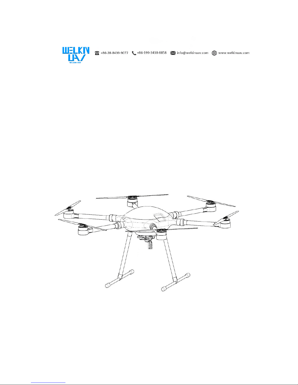
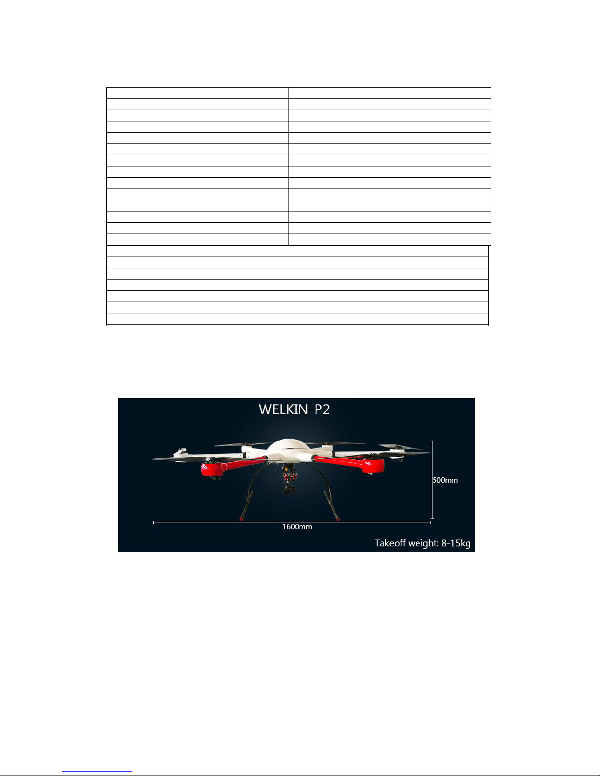
Welkin P2 is an industrial grade drone independently developed by our company. The airframe is made of
carbon fiber material, and the frame, upper cover, arm, landing gear and electric frame are all designed with
light structure. It is lighter and more beautiful while ensuring rigidity and strength. The arm is designed with
umbrella folding, which makes assembly and transportation quicker and more convenient. This product is
equipped with a multi-rotor flight control system independently developed by our company. The advanced
algorithm ensures the stability and safety of theflight platform.
Functionalcharacteristics
?Extra large payload, long enduranceandflight distance
?Quickrelease structure for easy carrying andtransportation
?Rainproofdesign, meet GJB150.8 (onthe standardof rain test)
?Carbonfiber integrated molding body,good rigidity andlight weight
?Windresistance upto 6levels (pass the seatest)
?Precise attitude control
?HD video, image output (in the caseof barrier free, the distance canreach30KM)
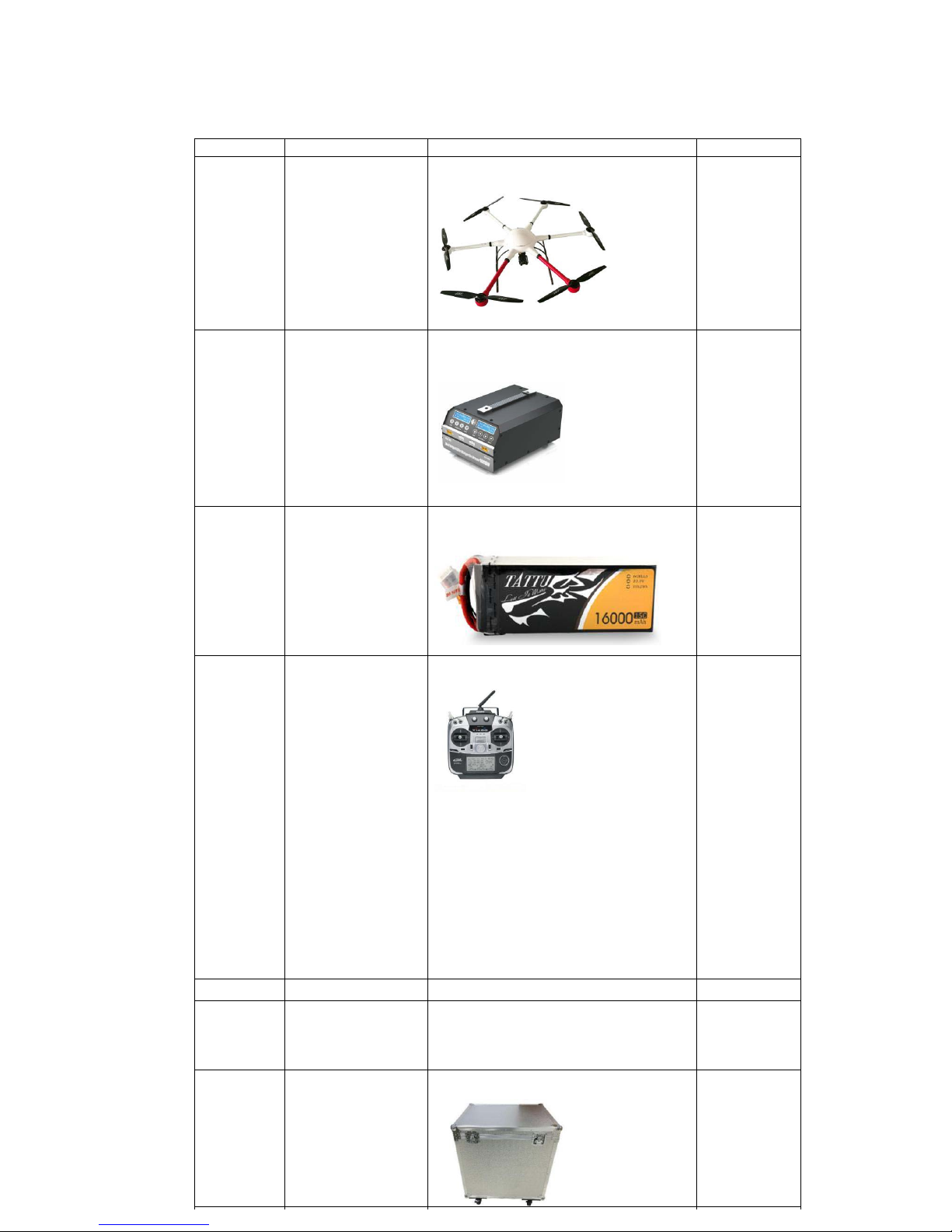
2. Product List
List
In order to facilitate transportation, Welkin P2 adopts a folding design, which has been tested for quality and
flight test before leaving the factory to ensure stable and reliable products. Before you start using it, checkthe
contentsof the package. The following is alist ofWelkin P2 items.

Table1Packing List

No. Name Reference Picture Quantity
1 Six-rotor drone body
1
2 Charger
1
3 Power Battery
2
4 Remote Control
1
5 GCS (Software) / 1
6 Task Equipment Depends on what equipment client buy
Depends on
how many
equipment
client buy
7 Flight Case
1

IndexParameter
Table3Remote ControlParameters
Table2Welkin P2 Parameters
Maximum Flight Course
60km
Cruise Speed
0~15m/s
Duration Time
70 min
Flight Height
1~4000m
Remote Control Distance
Maximum 40km (obstacle-free)
Control Mode
Automatic / Manual
Image Transmission Mode
Real Time Transmission
Image Transmission Format
1920*1080 HD (H.264);720*576 SD (MPEG-2)
Image Transmission Distance
Maximum 30km (obstacle-free)
Image Encryption Device
AES Encryption
Produce Size
1600*1600*500mm
TakeoffWeight
8~15kg
Waterproof Grade
Meet the standard of GJB 150.8 on rain test
Anti-wind Capability
≤6 Scale (Pass the sea test)
Remote control name: Futaba T14SG
Helicopter/fixed wing/multi-rotor compatible equipment
2.4GHz working frequency
Transmitter: 14SG 14 channel remote control *1
Receiver: Futaba R7008SB 2.4G high voltage plate receiver *1
Emitter: 6V, 1800amh (HT5F1800B)
Charger: HBC-3C special charger *1
Hanging band *1
Support SD card upgrade (Cards need to be purchased separately)
Input voltage
AC 100~240V
Output power 1080W (540W*2)
Charging current
1~20A*2 (adjustable)
Maximum balance current
1.2A
Battery type
lithium battery, high voltage lithium battery
Number of lithium battery sections
6 knots * 2 (6S)
Charging mode
fast charging, balanced charging mode, storage and
maintenance
Si
272 202 118 6

Maximum Flight Course
60km
Cruise Speed
0~15m/s
Duration Time
70 min
Flight Height
1~4000m
Remote Control Distance
Maximum 40km (obstacle-free)
Control Mode
Automatic / Manual
Image Transmission Mode
Real Time Transmission
Image Transmission Format
1920*1080 HD (H.264);720*576 SD (MPEG-2)
Image Transmission Distance
Maximum 30km (obstacle-free)
Image Encryption Device
AES Encryption
Produce Size
1600*1600*500mm
TakeoffWeight
8~15kg
Waterproof Grade
Meet the standard of GJB 150.8 on rain test
Anti-wind Capability
≤6 Scale (Pass the sea test)
Remote control name: Futaba T14SG
Helicopter/fixed wing/multi-rotor compatible equipment
2.4GHz working frequency
Transmitter: 14SG 14 channel remote control *1
Receiver: Futaba R7008SB 2.4G high voltage plate receiver *1

Table4ChargerParameters
3. Component
FuselageParameters
Maximum Flight Course 60km
Cruise Speed
0~15m/s
Duration Time
70 min
Flight Height
1~4000m
Remote Control Distance
Maximum 40km (obstacle-free)
Control Mode
Automatic / Manual
Image Transmission Mode
Real Time Transmission
Image Transmission Format
1920*1080 HD (H.264);720*576 SD (MPEG-2)
Image Transmission Distance Maximum 30km (obstacle-free)
Image Encryption Device
AES Encryption
Produce Size
1600*1600*500mm
TakeoffWeight
8~15kg
Waterproof Grade
Meet the standard of GJB 150.8 on rain test
Anti-wind Capability
≤6 Scale (Pass the sea test)
Remote control name: Futaba T14SG
Helicopter/fixed wing/multi-rotor compatible equipment
2.4GHz working frequency
Transmitter: 14SG 14 channel remote control *1
Receiver: Futaba R7008SB 2.4G high voltage plate receiver *1
Emitter: 6V, 1800amh (HT5F1800B)
Charger: HBC-3C special charger *1

ComponentDescription


4. SystemOperationDescription
OperationProcess
EnvironmentalConfirmation
1.Pay attention to the choice of the flight site. Please do not fly in areas with large human
flow, manyfloors, high voltage powerlines, and airport restrictions. Please lookfor empty
spacewithout high-rise building shelter to fly.
1Pay attention to the choice of landing site, pay attention to the height of the
highest building to determine thereturn altitude;
2Do not fly in harshenvironments, suchas strong winds or rainydays;
3It is forbidden to fly in areas with strong magnetic field interference, such as steel
bridges and basestations;
4Do not operatewith propellers indoors;
5Checkif the routemeets theabove requirements;
6Checkif the GPS is normal andcheckif theGPS tracker is carried.
SystemCheck(beforepoweron)

1. Check if the aircraft outer cover, arms, landing gear, joint of arms and fuselage have
cracks or damage;
2. Checkif the GPS moduleis installed in the correctdirection;
3. Make sure that the screw at thejoint is tightened;
4. Check if the direction of the blade is correct and there is no damage (blade surface crack
or edge cracking);
5. Checkif the bladefixing tightness is appropriate;
6. Checkif the motor is firm (whether the outer rotor andtheinner stator fit together);
7. Checkif the guide is fixed firmly;
8. Checkthelandinggearforloosenessanddamage;
9. Checkif the battery compartment is in place andfixed firmly;
10. Checkif thepower of battery is sufficient;
11. Checkif the mission equipmentis fixed firmly;
12. Checkif thepower supplyline andtransmission line of thetask equipment are connected.
13. Checkthecenterofgravityoftheaircraftinthecaseofbatteryandtaskequipmentinstalled.
14. Checkthe battery powerof remote control;
15. Checkif theremote control channel is reset.
16. Pleasebesuretoturnontheremotecontrolbeforepoweringuptheaircraft.

SystemCheck(afterpoweron)
1Checkthe tightness ofthe power plug;
2Checkif the ledlight flashes normally;
3Checkif the settings of out-of-control protection andlow voltage protectionare
normal;
4Check if the retract of landing gear is normal (An aircraft with a retractable
functional landing gear);
5Calibrate geomagnetism (Whenit in a new flight environment);
6Checkif the task device control is normal;
7Check if the power supply status and data, image transmission function is normal,
ensure the connection between the aircraft and the ground station is successful, and
ensure that the signal strength is good;
8Check if the remote control signal is normal. The remote control calibration needs
to confirm that if the remote control channels are normal through the calibration page. In
the case of more than one remote controller in the field, make sure that the receiver only
corresponds to one remote controller.
GroundStationandAutonomousRouteConfirmation
1Checkif the GPS signal is normal, pleaseensurethat the number ofsatellites more
than 10;
2Checkif the flight control self-test items are all normal;
3Voltage calibration needs to measure the actual battery voltage. If the voltage
difference with the software feedback is greater than 0.1V, please be sure to select the
correct battery type and number of cells;
4Checkif the correspondingposture ofthe aircraft is correct;
5Confirm the height of all way points, they all needs to be higher than the actual
environmental altitude(if necessary,you canuse asmall aircraft to test theflight route);
6Make sure that there are noobstacles onall route lines.

CheckItemsInFlight
1The aircraft needs to switch to GPS mode when it is about 10m high from the
ground, and hover above 5seconds at fixed point to checkif the hover is normal;
2Checkif the magnetic compass is normal;
3Checkif the remote controlis normal underthe attitudemode andGSPmode;
4Please pay attention to the battery voltage. When the voltage is insufficient, please
return and landin time;
5Keep the remote control open all the time, and switch flight mode to GPS mode.
Push the throttle to 50%, and keep it during the whole flight until landing then push the
throttle down to 0%.
LandingCheck
1. The landinggear must be deployed beforelanding.
1Checkiftheenvironmentofreturnpointandthelandingpadaresafe;
2Checkthesituationofaircraftvoltage.
CheckAfterLanding(onebyone)
Do notapproach the aircraft until the propeller hasstopped.
1Ensure that the aircraft has beenlocked;
2Save the data first, then power off the aircraft, and then close the remote control,
map transmission, ground station andother storage components;
3Folding machine arms, folding paddles, paddle supports and etc to put into the
case. (Note that the high temperature batteryshould beplacedat room temperature
andthenboxed);
4Pay attention to the storage voltage of the battery (22.2V);
5The package is dust-proof andmoisture-proof.

Compasscalibration
The compass is easily interfered by other electronic devices, resulting in abnormal flight
data to cause the normal flight , and even flight accidents, we need often calibrate the
compass to keep the compass in optimal working condition (recommended to calibrate
the compass before the first flight)


[Note] ①Please do not calibrate in areas containing ferromagnetic materials, such as magnetic
mines,parking lots, buildingareas with undergroundsteel bars andetc.
Please do not carry ferromagnetic materials with you when calibrating. Such as keys and mobile
phones,
Compass modules cannot beused normally in theArctic Circle.
Compass calibration is very important, otherwise thesystem will not work normally.
5. HowtoRecharge
ProductFeatures

LiPoBATT(dronebattery) charging
1. Pleasetakeoutthebatteryandconnectittothecharger.
Insert the charger into the power supply, connect the battery, and display the interface after opening the switch.
1AdjusttheSTATUStoadjusttoLiPoBATT(lithiumbattery).
2Press ENTER to confirm.
3PressENTERtojumptothecurrentadjustmentstateandpressSTATUStoadjustto8.0A.

4Press ENTER to enter into the voltage adjustment state, press STATUS button to adjust to
22.2V(6S), pressENTER to confirm.
5LongpressENTERtoenterintothe[CONFIRM]interface.

Adjustment interface diagram
Other state diagram
CANCEL(STOP) interface diagram
1Cancel the selection without pressing any keys, restore to [current and voltage adjustment interface].
2Press ENTER to enter into the charging state, the current, voltage, charging duration and current
charging capacity will be showed.
Table of contents