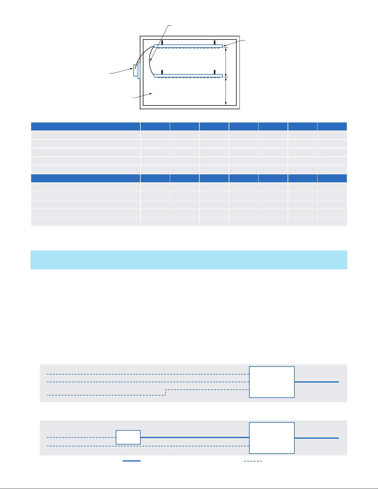
FIGURE 5 Bottom view of PB-CP control panel
FIGURE 4 Left view of PB-CP control panel
DUAL BAR SYSTEM WIRING INSTRUCTIONS
For applications where two linked BARs are required, follow the wiring instructions listed below. Accessories
Required: 3 x Ring Terminals per (2) BAR system.
Remove the white cover plate with the Plasma Air logo from BAR #1 exposing its ring terminals.
1. Snip the control panel connector off the end of the wiring from BAR #2 and attach the new ring terminals to the
loose wire ends.
2. Lay the new ring terminals from BAR #2 on
top of the exposed ring terminals on BAR #1.
3. Reattach the cover plate on BAR #1. Connect
BAR #1 to the Control Panel using the
standard factory connector.
OPERATION
1. When power is supplied to the Plasma BAR
Control Panel and the switch is in the "on"
position, the Plasma BAR ionization assembly
will be activated with the supply fan.
2. The Plasma BAR ionization unit is self
balancing and does not require any type of
adjustment.
3. The benefit of the Plasma BAR ionization
system is realized only when the supply fan
is running. Therefore, to achieve improved
air quality, interlock the Plasma BAR Control
Panel to be activated with the supply fan.
MONITORING CIRCUIT
The Plasma BAR Control Panel includes a
monitoring circuit to verify operation status. The
circuit consists of a relay with isolated normally
open contacts. The contacts remain open
whenever the ionization system is not powered
or if there is a fault in the equipment. Whenever
the ionizer is energized and producing ions, the
normally open contacts close and the green
ion indicator light will illuminate. Connect
the monitoring control wires of the Building
Automation System (BAS) to the dry contacts on
the unit. (See Figure 4 & 5).
TROUBLESHOOTING & MAINTENANCE
The Plasma BAR ionizer should be inspected annually to ensure optimal performance. If any dust has built up on
the tip of the ionizing needles, this can be removed using a simple cotton swab or compressed air. The control
panel requires no maintenance of any kind.
1. If the Plasma BAR ionization unit is not working, check that: The control panel power switch is in the "on"
position, the supply fan is running and the green ion indicator light is illuminated.
2. The power input connections to the control panel are properly connected. Verify all connections are correct
and securely tightened. Reconnect any loose wires.
3. Test the BAS alarm dry contacts using a multimeter set to continuity mode (Ohms symbol). If the multimeter
buzzes the circuit is continuous and operation is normal. If it does not buzz the circuit is broken. Verify other
steps and contact support if needed.
4. If the control panel internal fuse is blown, wait 2 minutes to allow the unit to automatically reset the fuse. Turn
on the power to the control panel. If the fuse blows again, return the control panel to the factory for service.
SEQUENCE OF OPERATION
1. For units that are interlocked with the supply fan control, the BAS controls the start/stop of the air conditioning
unit supply fan.
2. After a one minute time delay on a call for supply fan operation, the BAS monitors the ionization system via the
control panel.
3. Open contacts indicate a fault; closed contacts indicate normal operation.
3540 Toringdon Way Suite 200, Charlotte, NC 28277
phone 1 866 508 1118 www.plasma-air.com info@plasma-air.com
200080-C
© 2023 All rights reserved
GREEN LED
IONIZATION
LIGHT
(MAY APPEAR
SLIGHTLY DIFFERENT
THAN PICTURED)
ON/OFF
SWITCH
12 VOLT DC
IN/OUT PIN
(2.1mm pin)
DRY CONTACTS
FOR BAS
MONITORING
24 VOLT AC
POWER INPUT
CONNECTION