Welldana Innocare Medial User manual

Operating instructions Medial
_________________________
__________________________
2
Please read this operating instructions carefully before placing
the health care bed into operation
Our company sets high standards on quality and customer satisfaction
In this context we always want you to receive the best possible advice and
if you have further questions or need for information concerning our special equipment please contact
us:
On the following pages you’ll find the mode of operation and material handling of our health care beds:
Model „Medial“
The health care beds are produced according to DIN EN 1970 – 2000 (standard for health care beds)
as well as
DIN EN 60601-2-38 (standard for nursing beds / in dependence on)
In the following operating instructions you’ll receive detailed illustration and specification on:
•Assembling of the health care bed
•Operation of the moveable devices
•Service and maintenance
•Service book in the appendix
Subject to technical modifications without prior notice
2
Contents 1.0-12.0
Click to buy NOW!
P
D
F
-
X
C
H
A
N
G
E
w
w
w
.
d
o
c
u
-
t
r
a
c
k
.
c
o
m
Click to buy NOW!
P
D
F
-
X
C
H
A
N
G
E
w
w
w
.
d
o
c
u
-
t
r
a
c
k
.
c
o
m

Operating instructions Medial
_________________________
__________________________
3
1.0 General instructions 4-10
1.1 General instructions + storage condition 4-5
For the special equipment „Trendelenburg positions“
please connect the accumulator battery!
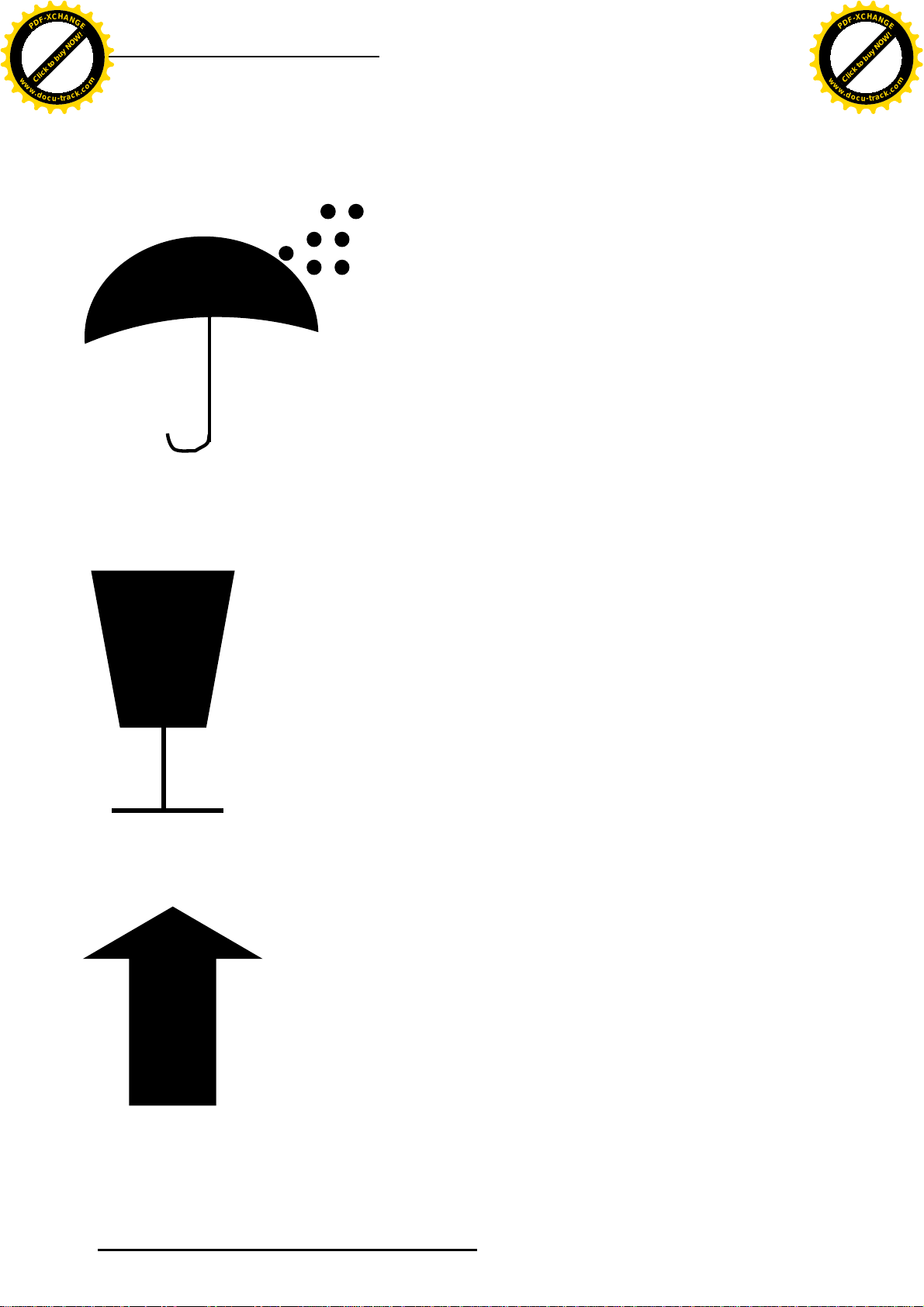
1.2 Symbols in use - Illustration 5-7
1.3 Packages 8
1.4 Special characteristics 8
1.5 Purpose / Range of use 8
1.6 commodities in use 9
1.7 Maintenance and recommended cleaning products 9
1.8 Design and assembly 10
1.9 Mattress 10
2.0 Assembly-instructions 10-16
2.1 Assembling the health care bed 10-11
2.2 Assembling the central drive unit 11-12
2.3 Assembling the lying surface with front modules 13-14
2.4 Assembling the wooden side-rails 14-16
3.0 Connection and cabling 16-23
3.1 Connection and laying of all cables 16-17
3.2 line cord (main connection) 17-18
3.3 Function control 19-20
3.4 Safety margin 20-22
3.5 Disassembly 22
3.6 Emergency prone position release 22-23
4.0 Functional characteristics 24-26
4.1 Backrest 24
4.2 Leg rest with knee angle 24-25
4.3 side-rail features 25
4.4 castor locking device 25
4.5 lying surface level adjustment 26
4.6 Moving the bed with a patient 26
5.0 Accessories/ special equipment 27
5.1 Lift-up device with grab handle 27
5.2 Retractable side-rails (special equipment) 27
5.3 Backrest retractor - DBFK (special equipment) 27
5.4 Health care bed mattress 27
5.5 Attaching the lifter 27-28
6.0 Electrical components 28-32
6.1 Drive unit 28
6.2 Height adjustment motors 28
6.3 Manual control unit and locking device 29
(Trendelenburg adjustment) 29-31
7.0 Maintenance 31-33
7.1 Maintenance rate 31
7.2 Checklist for malfunctions 32-33
8.0 Technical characteristics 33
8.1 dimensions 33
8.2 weights 31
8.3 castor types 31
9.0 Electrical data 34
10.0 Maintenance- Checklist 34-37
11.0 Disposal 37
12.0 Maintenance booklet 37-44
1.0 General instructions 3
Click to buy NOW!
P
D
F
-
X
C
H
A
N
G
E
w
w
w
.
d
o
c
u
-
t
r
a
c
k
.
c
o
m
Click to buy NOW!
P
D
F
-
X
C
H
A
N
G
E
w
w
w
.
d
o
c
u
-
t
r
a
c
k
.
c
o
m

Operating instructions Medial
_________________________
__________________________
4
1.1 General
Please read these operating instructions carefully in order to prevent damage during assembling and
before placing the health care bed with slatted frame into operation
Only accessories from Fa. Müller Kranken- und Pflegeeinrichtungen Werner Mühle GmbHwhich were
delivered with the bed (accessory kit) or were ordered as special equipment are to be used. The list for
special equipment is in 5.0
The user has to assure oneself of the good order and condition of the health care bed. On long-term
application (every 12 months) or reuse after storage it is necessary to check its functions and look for
visible damages.
The health care beds are produced following DIN EN 1970 – 2000 (standard for health care beds)
as well as
DIN EN 60601-2-38 (= standard for nursing beds / in dependence on)
The drive units comply with the EN 60601-1 specification.
Certain constellations, like positioning the bed next to other electrical equipment – like radio or
television - may lead to electro-magnetic interferences. In this case remove the devices or change the
position of the bed.
Storage condition:
The health care bed should always be used under the following conditions:
Storage temperature: + 10° to max. + 40 ° C
Relative air humidity : 30 to 75%
Air pressure : 700 – 1000 Hektopascal
When your bed has the special feature „Trendelenburg-position“it is possible to move the bed
with the charged accumulator battery only (without any further external power supply)
This shall secure the prone positioning in case of power blackout while Trendelenburg position.
If the bed is to bed stored for a longer period, a patient is transported in the bed or the power
supply is cut for security reasons it is absolutely necessary to unplug the connection from the
accumulator battery to the laying surface motor in order to prevent any unwanted displacing of
the health care bed. (see photo)
1. Remove the cap with a standard Phillips head screw driver
2. Here the accumulator battery is connected!
3. Unplug the plug and disconnect the accumulator power supply!
Finally you have to screw the cap back on the multiway connector!
1.2 Symbols in use - Illustration
Click to buy NOW!
P
D
F
-
X
C
H
A
N
G
E
w
w
w
.
d
o
c
u
-
t
r
a
c
k
.
c
o
m
Click to buy NOW!
P
D
F
-
X
C
H
A
N
G
E
w
w
w
.
d
o
c
u
-
t
r
a
c
k
.
c
o
m

Operating instructions Medial
_________________________
__________________________
5
4
This symbol indicates: Take notice of operating instructions!
This symbol indicates: application part - type B
IP 44
This symbol indicates: protection class – protected against access to dangerous parts with a wire,
protected against contaminants D = > 1 mm. protected against splash water.
IP X4
This symbol indicates: Protected against splash water.
This symbol indicates: double protective insulation
This symbol indicates: Evidence of conformity of medical products and devices – reference 93/42/EWG
Click to buy NOW!
P
D
F
-
X
C
H
A
N
G
E
w
w
w
.
d
o
c
u
-
t
r
a
c
k
.
c
o
m
Click to buy NOW!
P
D
F
-
X
C
H
A
N
G
E
w
w
w
.
d
o
c
u
-
t
r
a
c
k
.
c
o
m

Operating instructions Medial
_________________________
__________________________
6
This symbol indicates:
This sign you’ll find on the packing and indicates:
Direction of arrow must be up during storage, transport and
unpacking.
Keep of wetness!!
Don’t throw! Keep careful – fragile!
This way up!!!!
Click to buy NOW!
P
D
F
-
X
C
H
A
N
G
E
w
w
w
.
d
o
c
u
-
t
r
a
c
k
.
c
o
m
Click to buy NOW!
P
D
F
-
X
C
H
A
N
G
E
w
w
w
.
d
o
c
u
-
t
r
a
c
k
.
c
o
m

Operating instructions Medial
_________________________
__________________________
7
This sign you’ll find on the upper front motor shaft and
indicates:
Danger of being crushed!
1.3 Packages
(7 pieces)
1. Frontlifter including castors
2. Lying surface part (headpiece)
3. Lying surface part (footpiece)
4. Side-rails
5. Retractor including grab handle
6. Engine box including accessory kit
Contents of accessory kit :
•Main drive unit
•Manual control
•6 self-adhesive cableclips
•2 slugs (allen) M 8 x 16
•Allen wrench
•Side-rail guide pusher (4 pieces)
Please check the completeness of the contents before assembling
1.4 Special characteristics
-Electrical level adjustment of the lying surface from 40 - 80 cm
-Electrical adjustment of the backrest 0 to 70°
-Electrical adjustment of the knee angle 0 to – 20°
-Only with special equipment Trendelenburg position:
Trendelenburg bedding (inclined position of head and foot section) (switch off possibility via
manual control)
1.5 Purpose / Range of use
The health car bed „Medial“ is especially designed for the home care area. The health care bed shall
facilitate the care of indigent or older people at home. It is not designed to be connected with other
medical electric devices. The health care bed is not fitted to be employed in hospitals or other fields of
medical care.
The safe workload is 1700 N (~ 170 kg) which include mattress (20 kg) as well as accessories
(15 kg). This leads to a maximum permitted weight of the patient of 135 kg.
The health care bed is not suitable for patients who measure less than 150 cm or more than 190 cm
(based on a lying surface length of 200 cm).
It is furthermore necessary to indicate the possible risk of crushing for emaciated patients since in this
case the standard security distance won’t be sufficient. For security reasons we advise you to put a
side-rail protection or protective cushions/ hose in use. This can be ordered via our service hotline or at
the specialised rehabilitation supply dealers.
Before operating make sure that the side-rails are in perfect condition and fully functioning
(see also 2.4).
Click to buy NOW!
P
D
F
-
X
C
H
A
N
G
E
w
w
w
.
d
o
c
u
-
t
r
a
c
k
.
c
o
m
Click to buy NOW!
P
D
F
-
X
C
H
A
N
G
E
w
w
w
.
d
o
c
u
-
t
r
a
c
k
.
c
o
m

Operating instructions Medial
_________________________
__________________________
8
The use of the side-rails is limited to securing members not to fall off laterally. To access and get out of
the bed it is absolutely necessary to put the wooden side-rails in its lowest position
There are no electro medical appliances in our beds permitted!
1.6 Basic materials in use
Several components of the health care bed are partly made of permanently powder- coated steel. The
derived timber products all have a high-quality surface-coating. All side rails are made of sheathed solid
plywood (spruce fir).
The solid wood is coated with an environment- and skin-friendly varnish. The sprung slats are made of
special surface-sealed plywood
1.7 Maintenance and recommended cleaning products
In order to ensure the economic life-time of your health care bed we strongly recommend as follows:
•Clean all metallic and wooden parts with a damp cloth only
•The same applies for the electrical engine; this one must not be cleaned with a high-pressure
cleaner.
•Due to hygienic reasons we recommend not to use any lubricants for the moveable parts.
•Do not use any tools like palette-knifes, knifes or similar.
•Do not use coarse-grained scouring agent
Please only use by the Robert Koch institute certified and approved disinfecting agents (Sagrotan) for
disinfecting the health care bed.
These are to be applied with a spray bottle and/or a cloth (made of cotton or microfiber) on the inlay
frame in order to clean and disinfect it. Apply the disinfecting agent through wiping with the cloth. We
strongly recommend removing the disinfecting agent after its residence time in order to avoid any
possible skin irritation. Always wear rubber gloves when disinfecting or cleaning the health care
bed!
Abstract of "Robert Koch Institut Berlin Germany list:
Active agent:
Name:
Producer or
supplier
functional
attenuation
development
time
functional
attenuation
development
time
functional
attenuation
development
time
functional
attenuation
development
time
functional
attenuation
development
time
1
2
3
4
5
6
7
8
Amocid
Lysoform
Bacillotox
Bode Chemie
Phenol or
Gevisol
Schülke & Mayr
Phenol-
Helipur
Braun Melsungen
derivate
m-Kresolseifenlösung
DAB 6
Mucocit-F 2000
Merz
Phenol
Velicin forte
Henkel
Desinfection
von Ausscheidungen
1 part sputum or stool
+2 parts dilution
OR
1 part urine +
1 part dilution respectively
washing abrasive Sputum: Stool: Urine:
%
desinfection: desinfection:
5
% h. % h. % h. % h.
5
h.
1 12 5 6 5 4 5 6
5
2
1 12 6 4 5 4 5 6
6
2
0,5 12 5 4 5 4 5 6 2
6 4 6 4 6 6 2
1 12 5 4
1 12
1 12 3 2 5 4 5 6
Click to buy NOW!
P
D
F
-
X
C
H
A
N
G
E
w
w
w
.
d
o
c
u
-
t
r
a
c
k
.
c
o
m
Click to buy NOW!
P
D
F
-
X
C
H
A
N
G
E
w
w
w
.
d
o
c
u
-
t
r
a
c
k
.
c
o
m

Operating instructions Medial
_________________________
__________________________
9
1.8 Design and construction
It is possible to dismantle your health care bed into several portable parts which makes it easier to be
transported.
The health care bed can be completely assembled with the included tools (Allen key).
The lying surface is equipped with an electronically adjustable slatted frame. The backrest and the
knee-kink are individually adjustable and permit a comfortable position for the patient and the nursing
person respectively
A level adjustment (height adjustment) is possible via the head and food section (front) of the bed. It is
possible to choose between a parallel adjustment and a tangential deviation on the handset.
These parts of the bed are produced with welded steel tubing which has a varnish-annealed surface.
1.9 Mattress
Please use a special health care mattress RG 35 in accordance with DIN EN 597 of low flammability
with the following measurements:
Height: 120mm
Length: 2000 mm
Width: 900 mm
The measurements of length and width change accordingly to any changes of the lying surface,
i.e. 90 x 210 cm
This means that the mattress has got a length of 2100 mm.
It is recommended to install the heightened side-rails from our accessories-catalogue if other kinds of
back supports are used.
2.0 Assembly instructions
2.1 Assembling the health care bed
1. Operate the step-levers of the two front-modules as described in 4.4 and place them flat
against the wall – the square iron bars showing to the room-centre.
2. Both parts of the lying surface have to be stuck together at the butt joints and then tightened
manually with the enclosed winged screws (2 parts). The butt joints of the lying surfaces-halves
are the ones without a cross-iron bar at the outer frame
Grub Screws
(Enclosed in the accessories kit)
Winged bolt
3. We recommend placing both halves of the lying surface side-by-side on the floor and fitting the
parts in this position together. In addition to the winged
Click to buy NOW!
P
D
F
-
X
C
H
A
N
G
E
w
w
w
.
d
o
c
u
-
t
r
a
c
k
.
c
o
m
Click to buy NOW!
P
D
F
-
X
C
H
A
N
G
E
w
w
w
.
d
o
c
u
-
t
r
a
c
k
.
c
o
m

Operating instructions Medial
_________________________
__________________________
10
bolts one grub screw on both sides of the lying surface has to be screwed down with the allen key
(accessories kit).
2.2 Installation of the central drive unit underneath the lying surface
1. Put the lying surface on edge (heading-section-sticker upwards). The top side of the lying
surface should be put transversely to the wall. The pressure levers are showing to the centre of
the room.
Stickers showing to
the wall as follows:
-CE sign
- Heading-section
indication
- max. Indication of weight
- Serial sticker
- Indication for power
supply
- - Gewichtsangabe
2. The next step is to unfasten the winged
screws – as long as the lying surface stands
edgewise - at the heading- and foot section
and to re-screw them loosely (app. 3
revolutions).
Click to buy NOW!
P
D
F
-
X
C
H
A
N
G
E
w
w
w
.
d
o
c
u
-
t
r
a
c
k
.
c
o
m
Click to buy NOW!
P
D
F
-
X
C
H
A
N
G
E
w
w
w
.
d
o
c
u
-
t
r
a
c
k
.
c
o
m

Operating instructions Medial
_________________________
__________________________
11
Assembling the lying surface with the front modules
1. Put the lying surface down on the floor
in front of either of the front modules.
2. Stand behind the front module and raise
the lying surface regularly on the
rectangular tubes.
3. Insert the tube-ends of the lying surface above the rectangular tubes of the front module. Push
the lying surface as far as it will go (direction of arrow) towards the metal adapter plates of the
front modules.
4. After this tighten the loosely screwed winged bolts of the lying surface manually in order to get
a securely attached connection between the front-module and the lying surface.
Click to buy NOW!
P
D
F
-
X
C
H
A
N
G
E
w
w
w
.
d
o
c
u
-
t
r
a
c
k
.
c
o
m
Click to buy NOW!
P
D
F
-
X
C
H
A
N
G
E
w
w
w
.
d
o
c
u
-
t
r
a
c
k
.
c
o
m

Operating instructions Medial
_________________________
__________________________
12
5. Repeat this procedure for the other front-module (Raise the lying surface and insert it on the
rectangular tubes, etc.) and make sure to get a securely attached connection of the front
module and lying surface.
6. Finally the 4 location points to the front modules behind the winged bolts have to be screwed
tight with one grub screw each (Allen key of the accessories kit).
2.4 Installation of the side-rails
1. There are 2 side-rails on each bedside needed.
Caution: Rounding points upwards!
2. First of all it is necessary to attach the 2 guide pushers to the front section ( push the
lower snap fastener and insert the guide pusher head-up through the lower opening
of the aluminium-rail; the guide pusher has to slide easily back and forth the two
snap fasteners).
Head of guide-pusher
Please insert guide pusher like this in
the aluminium-rail.
3. Place the guide pusher at the
front and slip two wooden
side-rails on the fingers of the
guide pusher
Click to buy NOW!
P
D
F
-
X
C
H
A
N
G
E
w
w
w
.
d
o
c
u
-
t
r
a
c
k
.
c
o
m
Click to buy NOW!
P
D
F
-
X
C
H
A
N
G
E
w
w
w
.
d
o
c
u
-
t
r
a
c
k
.
c
o
m

Operating instructions Medial
_________________________
__________________________
13
4. Without holding on you can now attach the other end of the side rails to the guide pusher.
5. Insert the freehand-attached guide pusher into the aluminium-rail at the other front module.
(same procedure – please pay attention to the snap fasteners!)
4. Please repeat this procedure at the other bed side, too.
Information:
When adjusting the lying surface by inappropriate handling: Danger of being crushed between
side rails and lying surface!
Furthermore it is necessary to keep the side rails fully functional as they have been at the time
of delivery. i.e.: occasional cleaning of the aluminium- rails. Do not use any broken or defective
side rails.
For security reasons it is not permitted to use the side rails propped up diagonally.
(please refer to chapter 3.4!)
The ready-mounted side-rails are easily adjustable to the higher and lower position as shown on the
following figure.
Lowest position
Highest position
3.0 Connecting and laying of all plugs and cables
3.1 Connecting the power supply
Click to buy NOW!
P
D
F
-
X
C
H
A
N
G
E
w
w
w
.
d
o
c
u
-
t
r
a
c
k
.
c
o
m
Click to buy NOW!
P
D
F
-
X
C
H
A
N
G
E
w
w
w
.
d
o
c
u
-
t
r
a
c
k
.
c
o
m

Operating instructions Medial
_________________________
__________________________
14
The health care bed has to be placed near a power supply (socket)!
Voltage supply 230 Volt / 50 Hz
FOTO####################################################################
1. Remove the cap with a standard Phillips
head screw driver.
2. Plug the multipolar plug of the manual control switch in the receptacle of the drive unit.
Please refer to the symbols and figures on the drive unit!
1. 2.
3. The connecting cables (helix cable) at the front module placed engines
also have to be connected with the drive unit underneath the lying
surface at the preset receptacles!
Small round multipole
connector
Click to buy NOW!
P
D
F
-
X
C
H
A
N
G
E
w
w
w
.
d
o
c
u
-
t
r
a
c
k
.
c
o
m
Click to buy NOW!
P
D
F
-
X
C
H
A
N
G
E
w
w
w
.
d
o
c
u
-
t
r
a
c
k
.
c
o
m

Operating instructions Medial
_________________________
__________________________
15
Attention:
If the small round connector is not plugged, the motor will not run.
The cables of the two hoist motors have to be plugged in the designated receptacles on the drive unit
underneath the lying surface
4. Spare cable, coming from the drive unit can be fixed under the lying surface frame using the self-
adhesive cable routing clips (accessories kit).
3.2 line cord (Main connection cable)
In order to prevent any sagging the front hoist-motor cables also have to be secured by cable
routing clips as shown in the illustration below!
The strain relief (Anti-kink included) which is pushed on the line
cord disposes of two mounting nuts. One mounting nut fixes the
strain relief to the line cord and the other mounting nut fixes the
strain relief to the lying surface.
Please make sure that the line cord from the motor to the strain
like this! relief is neither too tight nor sagging!
Finally it is necessary to check the correct and tight position of the strain relief, otherwise
screw it with the big rear plastic nut until it is locked.
Refer to illustration above
Caution: When running the cables please make sure that they cannot
be damaged by any moveable parts. Furthermore it is necessary to
Click to buy NOW!
P
D
F
-
X
C
H
A
N
G
E
w
w
w
.
d
o
c
u
-
t
r
a
c
k
.
c
o
m
Click to buy NOW!
P
D
F
-
X
C
H
A
N
G
E
w
w
w
.
d
o
c
u
-
t
r
a
c
k
.
c
o
m

Operating instructions Medial
_________________________
__________________________
16
prevent sagging cables which could constrain the sub-driveability
and mobility of the health care bed!
Please use enclosed self-adhesive cable routing clips
Information: To avoid any confusion every plug is different and
fits in only one socket.
Please do not force the plugs when plugging in!
3.3 Function control + security dimensions
Before starting the function control please re-screw the cap above the plugs back on the main
drive unit.
•Plug the main connection cable in a standard 220 V socket and establish the electricity supply.
•Please perform now a function control of the electrical drive units by using the manual control
(please refer to 6.3 activating the manual control)
•For this move all drive units in their respective end-position
•While proceeding, make sure that there are no parts colliding.
Due to security reasons the following internal dimensions are to be kept and may under no
circumstances exceed the limits!
900 x 2000 mm internal space!
Top- view on
the health
care bed
Click to buy NOW!
P
D
F
-
X
C
H
A
N
G
E
w
w
w
.
d
o
c
u
-
t
r
a
c
k
.
c
o
m
Click to buy NOW!
P
D
F
-
X
C
H
A
N
G
E
w
w
w
.
d
o
c
u
-
t
r
a
c
k
.
c
o
m

Operating instructions Medial
_________________________
__________________________
17
•Avoid putting extremities in the danger zone during the moving process of the drive units/
adjustable range of the health care bed. ( Refer also to 4.0!)
•There are no electro-medical appliances permitted in our health care beds!
The minimum
separation distance
between the
side rails and the
moveable parts
of the bed must not
be less than:
min. 25 mm!
(Only use
recommended
mattress-sizes as
described in 5.4!)
3.4 Security dimensions
Pay attention for always keeping the following security dimensions:
A= < 120mm H = Lowest position = 400mm from floor to upper edge Lying
surface.
Measurements in mm!
View on lowest lying position
Click to buy NOW!
P
D
F
-
X
C
H
A
N
G
E
w
w
w
.
d
o
c
u
-
t
r
a
c
k
.
c
o
m
Click to buy NOW!
P
D
F
-
X
C
H
A
N
G
E
w
w
w
.
d
o
c
u
-
t
r
a
c
k
.
c
o
m

Operating instructions Medial
_________________________
__________________________
18
H
Highest position = 800 mm
Security dimensions for one-piece side rails
Also refer to the table on the following page:
Illustration and table according to DIN EN 1970:2000
Click to buy NOW!
P
D
F
-
X
C
H
A
N
G
E
w
w
w
.
d
o
c
u
-
t
r
a
c
k
.
c
o
m
Click to buy NOW!
P
D
F
-
X
C
H
A
N
G
E
w
w
w
.
d
o
c
u
-
t
r
a
c
k
.
c
o
m

Operating instructions Medial
_________________________
__________________________
19
DDistance between front- and bottom
end/ accessories and side rails/ grab
handles to the bed-bottom in levelled
position
D less than 60 mm
or
D more than 250 mm
EBiggest dimension in at least one
direction of each accessible opening
below the side rails
Either:
D bigger than
250mm
then
E less than 60mm
or
D less than 60mm
then
E less than 120mm
Description
from scratch Dimension - explanation Dimension-
requirements in mm
AHighest dimension between side rail
components at all normally used
positions. A less than 120mm
BThickness of the normally used
mattresses without compression and
bed-bottom in levelled position.
Manufacturer’s
Indication (refer to
accessories 5.4!)
CHeight of side rails’ upper edge above
the mattress without compression and
bed-bottom in levelled position. C bigger than 220mm
Click to buy NOW!
P
D
F
-
X
C
H
A
N
G
E
w
w
w
.
d
o
c
u
-
t
r
a
c
k
.
c
o
m
Click to buy NOW!
P
D
F
-
X
C
H
A
N
G
E
w
w
w
.
d
o
c
u
-
t
r
a
c
k
.
c
o
m

Operating instructions Medial
_________________________
__________________________
20
3.5 Dismantling
Warning: When shutting down the bed (without mattress) it is
possible that the hoisted leg rest won’t be lowered down –
even when the motor is moving to its back position since
the unlade leg rest is too light. The leg rest can fall down at
any indefinite point in time.
Note: The health care bed should only be shut down when the lying surface is
at a levelled position.
For dismantling the health care bed please follow the instructions in reverse order – that means from
3.3 to 2.1!
3.6 Emergency lowering device
The health care bed disposes of mechanical equipment for a so-called emergency handling.
With this device it is secured that in case of a power blackout the front end of the health care
bed can be lowered down manually.
For executing the emergency lowering device it is necessary to operate the red emergency lowering
device-lever at the lying surface engine (see illustration below).
Should the bed dispose of the special feature „Trendelenburg positioning” it is possible to lower the
headrest via the emergency lowering device lever, and additionally, the emergency lowering of the
bed height and inclined position through an integrated rechargeable battery pack in the engine.
For this it is highly recommended to take notice of the following points:
If the health care bed is stored away for a longer period, an in-patient is transported or the
electric power supply is cut off for other reasons it is imperative to unplug the plug and socket
connection from the rechargeable battery pack to the lying surface engine ( refer to pages 4+5!)
so that no unintentional kinetic moving of the health care bed is possible.
-Before the initial operation the rechargeable battery pack has to be charged for at least
10 hours (through Power plug – socket connection) so that the full operability of the
emergency lowering device is guaranteed.
-The state of charge of the rechargeable batty pack can be seen at the pilot-light on the
manual control switch ( refer to illustration below)
FLength of side rail (s) F bigger than 2/3
of lying surface
length
GDistance between front- and bottom
end without extending these
components
no
requirements
Click to buy NOW!
P
D
F
-
X
C
H
A
N
G
E
w
w
w
.
d
o
c
u
-
t
r
a
c
k
.
c
o
m
Click to buy NOW!
P
D
F
-
X
C
H
A
N
G
E
w
w
w
.
d
o
c
u
-
t
r
a
c
k
.
c
o
m
Table of contents