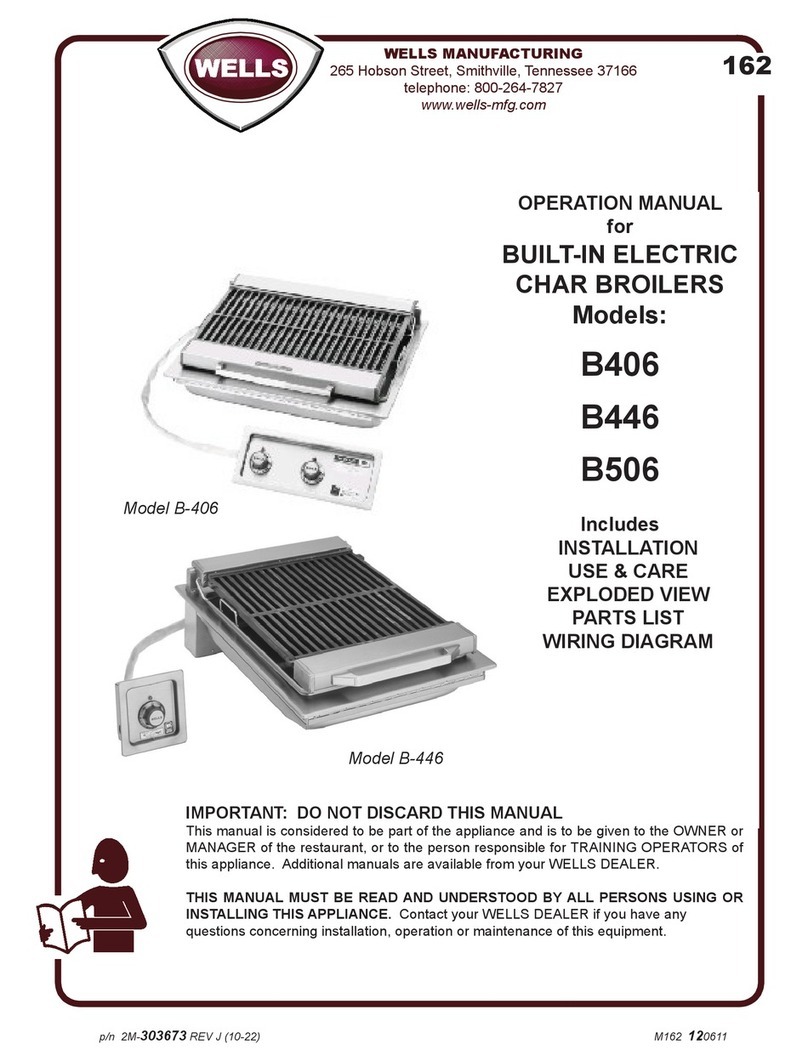
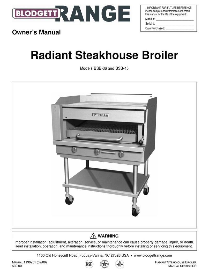
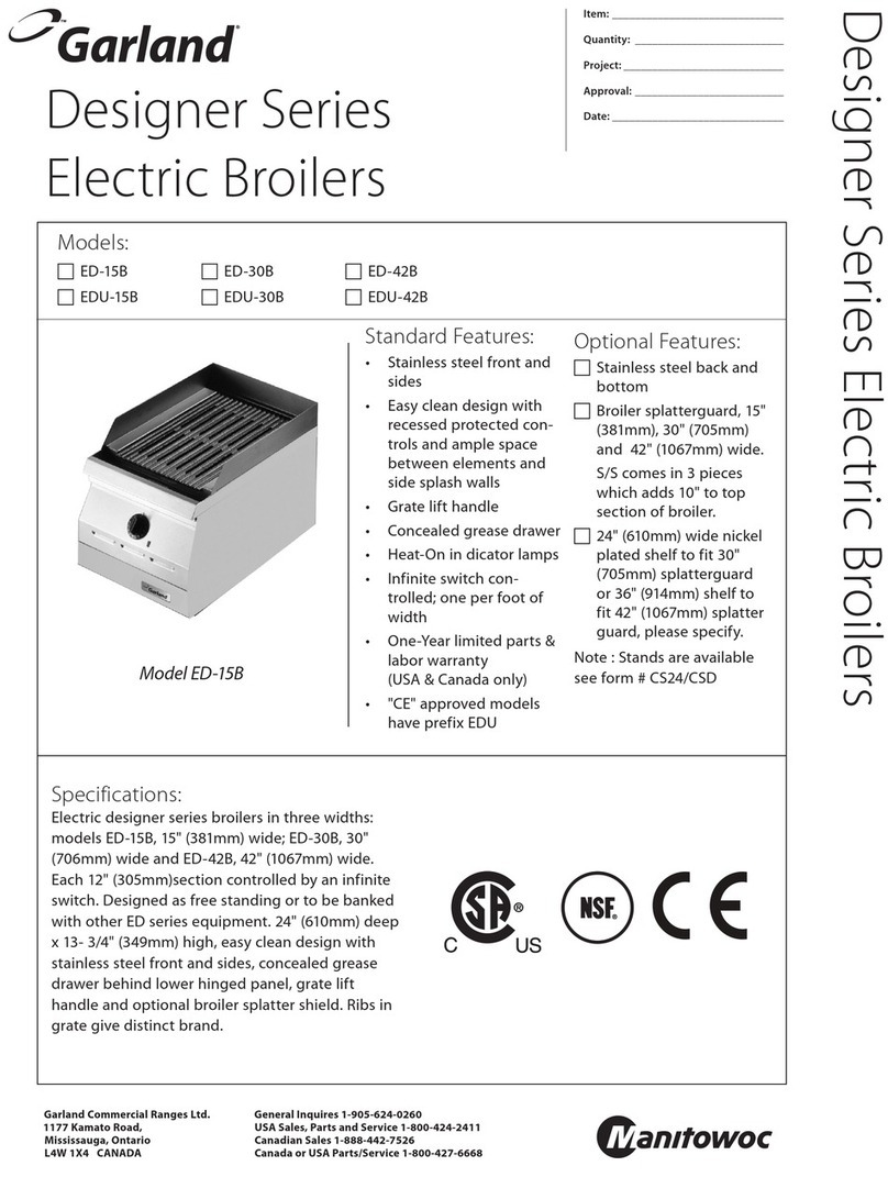
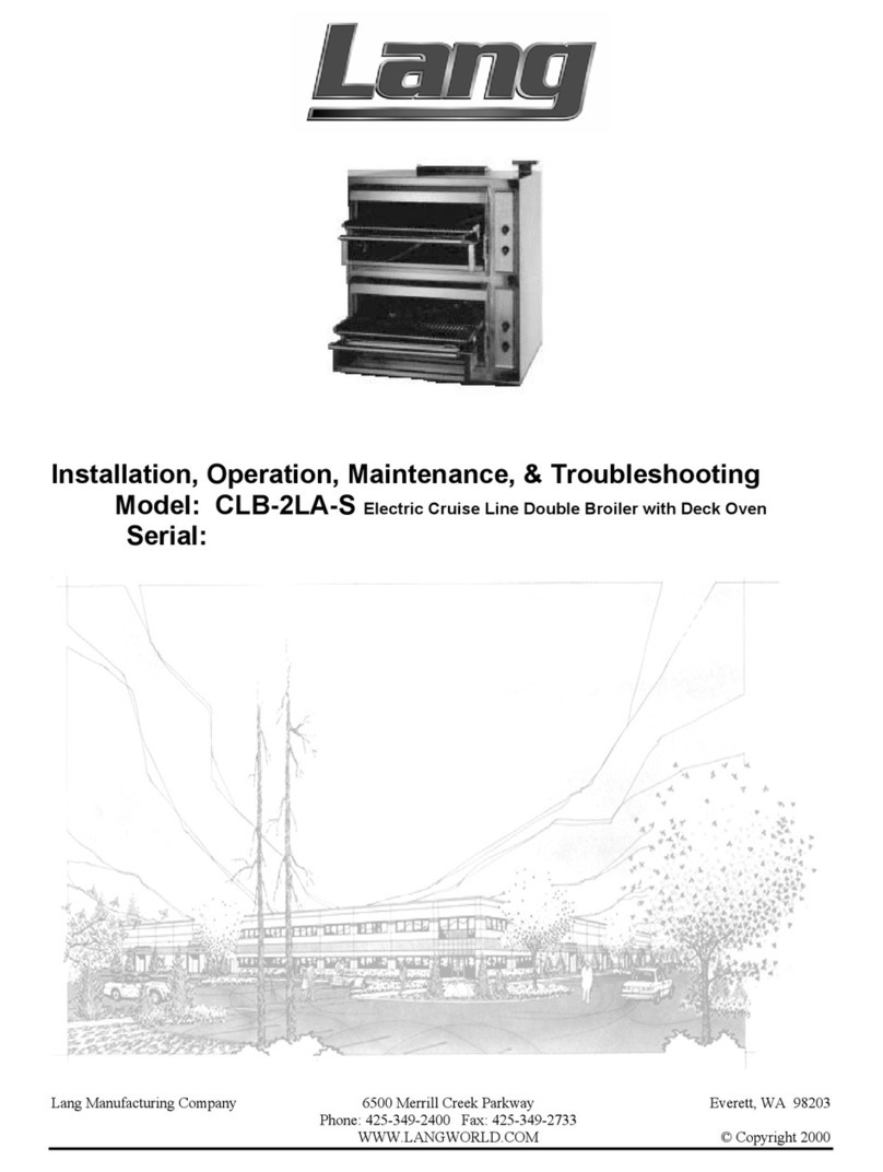
Wells B-50 Operating instructions

IMPORTANT: WELLS BLOOMFIELD, LLC PROPRIETARY INFORMATION.
DISSEMINATION OF THIS INFORMATION TO ANYONE OTHER THAN
WELLS AUTHORIZED SERVICE AGENTS IS STRICTLY PROHIBITED.
TECHNICAL CONTENT OF THIS MANUAL IS DESIGNED FOR
USE BY QUALIFIED PROFESSIONALTECHNICIANS ONLY.
PRINTED IN UNITED STATES OF AMERICA
WELLS BLOOMFIELD, LLC
2 ERIK CIRCLE, P. O. Box 280 Verdi, NV 89439
telephone: 775-689-5707
fax: 775-689-5976
www.wellsbloomfield.com
p/n SV161Rev.(-) S161 080910 cps
161
SUPPLEMENTAL
SERVICE
INSTRUCTIONS
ELECTRIC
CHARBROILERS
COUNTERTOP MODELS
B-40
B-44
B-50
BUILT-IN MODELS
B-406
B-446
B-506

GENERAL
This appliance is intended for use in commercial establishments
only.
This appliance is intended
to prepare food for human consumption.
No other use is
recommended or authorized by the manufacturer or its
agents.
Operators of this appliance must be familiar with the appliance use,
limitations and associated restrictions. Operating instructions must be
read and understood by all persons using or installing this appliance.
Cleanliness of this appliance is essential to good sanitation. Read and
follow all included cleaning instructions and schedules to ensure the
safety of the food product.
Disconnect this appliance from electrical power before performing any
maintenance or servicing.
Maintain 2" of water in drip pan at all times during operation. Do not
pour water over elements to refill drip pan.
DO NOT splash or pour water on, in or over any controls, control
panel or wiring.
DO NOT use water spray or steam jet to clean this appliance.
This appliance is not jet stream approved.
The technical content of this manual, including any wiring diagrams,
schematics, parts breakdown illustrations and/or adjustment
procedures, is intended for use by qualified technical personnel.
Any procedure which requires the use of tools must be performed by a
qualified technician.
This appliance is made in the USA. Unless otherwise noted, this
appliance has American sizes on all hardware.
WARNING:
RISK OF
INJURY
Installation procedures must
be performed by a qualified
technician with full knowledge
of all applicable electrical and
plumbing codes. Failure can
result in personal injury and
property damage.
WARNING:
ELECTRIC
SHOCK HAZARD
All servicing requiring access
to non-insulated electrical
components must be
performed by a qualified
technician.
Some procedures involve
exposed live circuits. Use all
due caution to avoid contact
with live electric circuits.
Failure to follow this warning
can result in severe electrical
shock.
CAUTION:
RISK OF
DAMAGE
DO NOT connect or energize
this appliance until all
installation instructions are
read and followed. Damage to
the appliance will result if
these instructions are not
followed.
PRECAUTIONS AND GENERAL INFORMATION
xi
SV161 SvcManual Electric Char-Broilers

GENERAL
GENERAL
Precautions & General Information …………….………… xi
Specifications ..……………………………...................….. 1
Features & Operating Controls ……………………………. 2
SERVICING INSTRUCTIONS
Troubleshooting Suggestions ......................................... 4
Prepare the Broiler for Use ............................................. 5
Replace Infinite Switch ................................................... 6
Replace Pivot for Element Head .................................... 7
Replace heating Element ............................................... 8
Replace Sopport Rod Spring .......................................... 10
EXPLODED VIEWS AND SERVICE PARTS
Control Knob Identification .............................................. 11
B-40 and B-406 ............................................................... 12
B-44 and B-446 .............................................................. 14
B-50 and B-556 .............................................................. 16
WIRING DIAGRAMS & SCHEMATICS
B-40 and B-406 ............................................................... 18
B-44 and B-446 .............................................................. 20
B-50 and B-556 .............................................................. 22
This manual contains information needed to properly service and repair Wells Bloomfield electric charbroilers.
This manual applies to the following Wells models:
B-40(6), B-44(6), B-50(6)
For installation, operation and maintenance instructions, refer to Operation Manual p/n 303672 (countertop
models), or Operation Manual p/n 303673 (built-in models).
TABLE OF CONTENTS
INTRODUCTION
1
SPECIFICATIONS
SV161 SvcManual Electric Char-Broilers
MODEL ELEMENT VOLTS KW AMPS PER LEG 3Ø AMPS
1Ø
POWER
CORD
(countertop only)
L1 L2 L3 NEUT
B-40
B406 SINGLE
ASSEMBLY 208 5.5 12.9 12.9 22.4 N/A 26.0 OPTIONAL
NEMA 6-30P
240 5.5 11.2 11.2 19.4 N/A 22.5
B-44
B-446 SINGLE
ASSEMBLY 208 5.5 11.5 22.4 14.4 N/A 26.0 NOT SUPPLIED
240 5.5 10.0 19.5 12.5 N/A 22.5
B-50
B-506 DUAL
ASSEMBLIES 208 11.0 30.0 30.0 30.0 N/A - NOT SUPPLIED
240 11.0 26.0 26.0 26.0 N/A 45.0

GENERAL
FEATURES & OPERATING CONTROLS
2
COUNTERTOP ELECTRIC CHARBROILER
IMPORTANT:
B-40 grate mounts above the element.
B-44 and B-50 grates can mount above or below the
elements.
Always remove a top-mounted grate before lifting the
element assembly.
IMPORTANT:
Remember to dis-engage the support rod before
lowering element assembly.
IMPORTANT:
DO NOT pour water over elements to refill drip pan.
SV161 SvcManual Electric Char-Broilers
ITEM COMMENT
TEMPERATURE
CONTROL The char-broiler is INFINITE SWITCH CONTROLLED. Power is applied to the
heating elements in a timed sequence based on the control knob position.
INDICATOR LIGHT Light will glow when the infinite switch is in any position other that OFF.
HEATING ELEMENT
ASSEMBLY
The char-broiler element assembly may be raised for cleaning, or to add water to
the drip pan. Use the handle to manually lift the grate. It is held the “up” position by
a support rod which automatically engages as the element is raised.
ELEMENT GUARD/
GRATE
The grate is designed to protect the individual elements from food contact and
spatula abrasion, resulting in prolonged element life and reduced carbonization.
The grate is easily removed for cleaning.
ELEMENT
SUPPORT ROD Holds element assembly in up position. Engages automatically when the element
assembly is raised. Must be disengaged manually before lowering elements.
DRIP PAN
The heavy-duty removable drip pan is located under the element assembly. The
drip pan catches food particles and grease drippings during broiler operation.
Maintain 2 inches of water in the drip pan at all times during operation of the broiler.
The drip pan is easily removed for cleaning.
DATA PLATE Gives manufacturer, make, model and serial number. Also voltage and phase
information, and agency approvals.
ADJUSTABLE LEGS The char-broiler is equipped with adjustable 4” legs.

GENERAL
FEATURES & OPERATING CONTROLS (continued)
3
SV161 SvcManual Electric Char-Broilers
ITEM COMMENT
TEMPERATURE
CONTROL The char-broiler is INFINITE SWITCH CONTROLLED. Power is applied to the
heating elements in a timed sequence based on the control knob position.
INDICATOR LIGHT Light will glow when the infinite switch is in any position other that OFF.
HEATING ELEMENT
ASSEMBLY
The char-broiler element assembly may be raised for cleaning, or to add water to
the drip pan. Use the handle to manually lift the grate. It is held the “up” position by
a support rod which automatically engages as the element is raised.
ELEMENT GUARD/
GRATE
The grate is designed to protect the individual elements from food contact and
spatula abrasion, resulting in prolonged element life and reduced carbonization.
The grate is easily removed for cleaning.
ELEMENT
SUPPORT ROD Holds element assembly in up position. Engages automatically when the element
assembly is raised. Must be disengaged manually before lowering elements.
DRIP PAN
The heavy-duty removable drip pan is located under the element assembly. The
drip pan catches food particles and grease drippings during broiler operation.
Maintain 2 inches of water in the drip pan at all times during operation of the broiler.
The drip pan is easily removed for cleaning.
DATA PLATE Gives manufacturer, make, model and serial number. Also voltage and phase
information, and agency approvals.
WELLSLOKS The broiler is equipped with WELLSLOKS, uniquely designed turnout tabs, which
help secure the broiler to the countertop.
BUILT-IN ELECTRIC CHARBROILER
IMPORTANT:
B-406 grate mounts above the element.
B-446 and B-506 grates can mount above or below
the elements.
Always remove a top-mounted grate before lifting
the element assembly.
IMPORTANT:
Remember to dis-engage the support rod before
lowering element assembly.
IMPORTANT:
DO NOT pour water over elements to refill drip pan.

SERVICING
4
SERVICING INSTRUCTIONS
TROUBLESHOOTING SUGGESTIONS
SYMPTON POSSIBLE CAUSE SUGGESTED REMEDY
Won’t heat- - no indicator
lights Not plugged in, or
Circuit breaker tripped. Check plug
Check / reset circuit breaker
One or more section won’t
heat—or not hot enough
Temperature control not set Set temperature control knob to
desired temperature
240V unit run on 208V Verify proper voltage
Damaged infinite switch Check/replace infinite switch
Check/repair wiring and terminals
Damaged heating element(s) Check/replace heating elements
Check/repair wiring and terminals
Temperature control not set Set temperature control knob to
desired temperature
208V unit run on 240V Verify proper voltage
Damaged infinite switch Check/replace infinite switch
Element assy loose, or
difficult to raise or lower Damaged hinge Repair/replace hinge
Element assy does not
latch in up position Damaged support rod assembly Clean/repair support rod
assembly
Replace support rod spring
One or more section too
hot
SV161 SvcManual Electric Char-Broilers

SERVICING
5
SERVICING INSTRUCTIONS (continued)
SV161 SvcManual Electric Char-Broilers
PREPARE THE CHAR-BROILER FOR USE
When using the broiler for the first
time, and after major repairs, wipe the
entire unit with a clean damp cloth or
sponge and mild detergent. Rinse
thoroughly clean water. Dry with a
soft clean cloth.
Remove the GRATE and raise the
ELEMENT ASSEMBLY.
Install the DRIP PAN and add
2” (5cm) of tap water.
Release the ELEMENT SUPPORT
ROD by lifting the element assembly
slightly, then pulling the lower portion
of the support rod forward. Gently
lower the ELEMENT ASSEMBLY.
MODEL B-40(6): Grate must be
installed ABOVE elements.
Install the GRATE, front edge first.
The TANGS of the grate go DOWN
and point toward the FRONT. The
grooves on the underside of the
grate align with the elements. The
rear edge of the grate can now be
lowered until it rests firmly on the
elements.
MODELS B-44(6) and B-50(6):
Grate(s) can be installed above or
below the elements.
ABOVE: Gently lower grate over
elements. The end with flush tabs
goes toward the front.
BELOW: Install one wing bolt in
each tab. The notch in the wing
rests on the lip of the drip pan. The
end with flush tabs must go toward
the front Adjust the wing bolts so
that , when the element assembly is
lowered, the top of the element is
1/4" (6mm) below the top of the
grate fins.
CAUTION:
HOT SURFACE
Exposed surfaces can be hot
to the touch and may cause
burns.
IMPORTANT: DO NOT
attempt to raise the element
assembly without first
removing the grate. Damage
to the hinges will result. Such
damage is NOT covered by
warranty.
IMPORTANT: Allow drip pan
to cool before removing from
the broiler.
DO NOT operate the broiler
without the drip pan installed.
DO NOT operate the broiler
without 2” (5cm) of water in
the drip pan.
IMPORTANT: DO NOT
attempt to lower the element
assembly without first
releasing the support rod.
Damage to the hinges will
result. Such damage is NOT
covered by warranty.
HANDLE
ELEMENT
GRATE TANG
FRONT
ELEMENT SUPPORT ROD
B-40(6) GRATE INSTALLATION
B-44(6) and B-50(6) GRATE INSTALLATION

SERVICING
SERVICING INSTRUCTIONS (continued)
6
SV161 SvcManual Electric Char-Broilers
REPLACE INFINITE SWITCH
COUNTERTOP UNITS:
1. Disconnect unit from electric power and allow to cool.
2. Remove control knob. Remove screws holding trim ring to cabinet.
Withdraw trim ring and switch.
3. Note orientation of switch to trim ring. Mark location of wires on
switch. Remove wires from switch. Remove and discard infinite
switch.
4. Mount new switch to trim ring, being careful to maintain proper
orientation. Connect wiring to switch. Remount trim ring and
switch in cabinet.
5. Reconnect to electric power and test for proper operation.
BUILT-IN UNITS:
1. Disconnect unit from electric power and allow to cool.
2. Remove control knob. Remove screws holding control panel to
cabinet. Withdraw control panel and switches.
3. Note orientation of switch on control panel. Mark location of wires
on switch. Remove wires from switch. Remove and discard infinite
switch.
4. Mount new switch to panel, being careful to maintain proper
orientation. Connect wiring to switch. Remount control panel
and switches into cabinet.
5. Reconnect to electric power and test for proper operation.
CAUTION:
HOT SURFACE
Exposed surfaces can be hot
to the touch and may cause
burns.
KNOB
TRIM RING (OR CONTROL PANEL)
INFINITE
SWITCH
P L1
H1
L2
H2
L2
L1
LOAD
INDICATOR
LIGHT

SERVICING
7
SERVICING INSTRUCTIONS (continued)
SV161 SvcManual Electric Char-Broilers
REPLACE PIVOT FOR ELEMENT ASSEMBLY
1. Disconnect unit from electric power and allow to cool.
2. Support the element head near the pivot to be replaced.
Remove the rear element cover.
Note and mark the location of the supply wires to the elements.
Disconnect the supply wires from the elements.
3. Remove the pivot cover. Store the pivot cover in a safe place.
Withdraw the element supply wires from the pivot.
Remove the screws holding the pivot to the cabinet. Withdraw the
old pivot.
4. Clean all old sealant from the cabinet at the pivot.
Apply a thin coat of high-temp food-grade lubricant to the pin of the
new pivot.
Apply food-grade silicone sealant to the bottom of the pivot.
Slide the pin of the pivot into the element head assembly, then
attach the pivot to the cabinet.
5. Thread the element supply wires through the pivot and re-connect
to the elements.
Reattach the pivot cover. For pivots with wires, be sure insulation
for pivot cover screw is in place.
Reattach the rear element cover.
6. Reconnect to electric power and test for proper operation.
CAUTION:
HOT SURFACE
Exposed surfaces can be hot
to the touch and may cause
burns.
IMPORTANT: DO NOT
attempt to raise the element
assembly without first
removing the grate. Damage
to the hinges will result. Such
damage is NOT covered by
warranty.
IMPORTANT: DO NOT
attempt to lower the element
assembly without first
releasing the support rod.
Damage to the hinges will
result. Such damage is NOT
covered by warranty.
PIVOT COVER
LEFT PIVOT
CENTER PIVOT
CENTER PIVOT
COVER
RIGHT PIVOT
PIVOT COVER SCREW INSULATION
FRONT
NOTE: B-50(6) dual pivot shown. Other units do not use the center pivot components.
Pivot cover screw insulation is used, where wiring passes through the pivot, to
minimize abrasion and chafing of the power wires.

SERVICING
SERVICING INSTRUCTIONS (continued)
8
SV161 SvcManual Electric Char-Broilers
REPLACE HEATING ELEMENT
1. Disconnect unit from electric power and allow to cool. Remove
grate.
2. Remove front and rear element covers. Note location of jumpers
and wires.
SUGGESTION: Removing a pivot will allow the element head to
be tipped on its side for better access to the element connection
screws.
3. Disconnect jumpers and wires from element to be removed.
Remove short jumpers from the front of all elements.
Remove element nuts from the front end of all elements.
Slide the front element support frame off of the elements.
4. Remove the rear element nut from all elements to be replaced.
Withdraw the old element from the rear element support frame and
discard.
5. Apply a small amount of anti-sieze to the element threads, then
attach the element to the rear element support frame.
NOTE: The element mounts such that the end with the shoulder is
positioned at the rear, the "flat" of the element is down, and the
electrical connection pad is toward the bottom.
6. Examine all rear elements for proper alignment, and all rear
element nuts for tightness.
7. Thread an element nut on the front end of the new element.
Run the nut inboard until a single thread remains exposed.
Examine all the other inboard element nuts to verify that only a
single thread remains exposed on each.
8. Slide the front element support frame over the elements.
NOTE: Position front element support frame such that the cover
mounting holes on its face are at the top, and the edge with the
cover mounting slot and threaded tabs is at the bottom.
Loosely reinstall all front element nuts.
Adjust front and inboard element nuts until the front and rear
element support frames are the same distance apart on right
and left ends.
Tighten front and inboard element nuts evenly.
9. Reconnect all jumpers and wiring. Reinstall element covers. If
any pivots were removed or loosened, be sure element support bar
is fully forward before reinstalling the element assembly on the
pivots.
10. Reconnect to electric power and test for proper operation.
Reinstall grate.
CAUTION:
HOT SURFACE
Exposed surfaces can be hot
to the touch and may cause
burns.
IMPORTANT: DO NOT
attempt to raise the element
assembly without first
removing the grate. Damage
to the hinges will result. Such
damage is NOT covered by
warranty.
IMPORTANT: DO NOT
attempt to lower the element
assembly without first
releasing the support rod.
Damage to the hinges will
result. Such damage is NOT
covered by warranty.
SUGGESTION:
At the rear element
connections, install upper
group of jumpers first, then
install lower group.
Installing jumpers in this
order will ease accessibility
conflicts.
IMPORTANT:
Review page 7 for
procedure on reinstalling
pivots.
SERVICING
9
SERVICING INSTRUCTIONS (continued)
SV161 SvcManual Electric Char-Broilers
15 21
FRONT
REAR
INSTALL
LAST
INSTALL
FIRST
FRONT
REAR ELEMENT
SUPPORT FRAME
FRONT ELEMENT
SUPPORT FRAME
SHORT JUMPER (FRONT)
HEATING ELEMENT
LONG JUMPER (REAR)
INBOARD ELEMENT NUT
REAR ELEMENT NUT
NOTE: SHOULDER
AT REAR END
FRONT ELEMENT NUT
NOTE: ALL JUMPER SCREWS
INSERT FROM BOTTOM
NOTE: NO SHOULDER
AT FRONT END
NOTE: B-44(6) shown. B-50(6) utilizes two identical element heads. B-40(6) is similar.

SERVICING
SERVICING INSTRUCTIONS (continued)
10
SV161 SvcManual Electric Char-Broilers
REPLACE SUPPORT ROD SPRING
1. Disconnect unit from electric power and allow to cool. Remove
grate.
2. Remove rear element cover.
Remove one pivot , then slide the element head off of the other
pivot.
3. Use a flat blade screwdriver to pry open the split end of the support
bar. Withdraw and discard all segments of the broken spring
4. Swing the support rod to the rear until the slot in the rod's split end
is vertical.
5. Slide the new spring into the support rod slot. The long finger must
be toward the outside and pointing toward the front.
6. Position the spring so that the short finger is fully seated in the
support rod slot. Then, use pliers to pinch the split end, capturing
the spring.
7. Rotate the long finger of the spring clockwise until it is captured by
the vertical walls at the back and side of the frame support casting.
8. Swing the support rod forward until it is against the elements, then
reinstall the element head on its pivots. Reinstall pivot.
9. Test the support rod for proper operation. It should spring into
position to support the element head when the head is raised.
10. Reinstall rear element cover.
11. Reconnect unit to elctric power and test for proper operation.
Reinstall grate.
CAUTION:
HOT SURFACE
Exposed surfaces can be hot
to the touch and may cause
burns.
IMPORTANT: DO NOT
attempt to raise the element
assembly without first
removing the grate. Damage
to the hinges will result. Such
damage is NOT covered by
warranty.
IMPORTANT: DO NOT
attempt to lower the element
assembly without first
releasing the support rod.
Damage to the hinges will
result. Such damage is NOT
covered by warranty.
SUPPORT
ROD SPRING
SUPPORT
ROD REMOVE
OLD SPRING
INSTALL
NEW SPRING
TENSION
NEW SPRING

EXPLODED VIEWS
11
EXPLODED VIEWS & SERVICE PARTS
SV161 SvcManual Electric Char-Broilers
CONTROL KNOB IDENTIFICATION
All versions of the Wells Electric Char-Broiler use control knob p/n 50371.
WELLS
OFF
LO
HI
8
7
6
5
4
3
2

EXPLODED VIEWS
EXPLODED VIEWS & SERVICE PARTS
12
SV161 SvcManual Electric Char-Broilers
B-40 COUNTERTOP CHAR-BROILER
WELLS
BRACKET COVER
52806
TRADEMARK
LABEL
53848
CONTROL KNOB
50371
TRIM RING
ASSEMBLY
50256
INFINITE SWITCH
CONTROL
54593
POP RIVET
54284
AMBER
LIGHT
SIGNAL
50516
4” ADJUSTABLE FEET (PK 4)
20563 STAINLESS
20314 PLASTIC
RIGHT PIVOT
BRACKET
52841
LEFT PIVOT
BRACKET
52840
TERMINAL BLOCK
50131
SUPPORT ROD
52729
HANDLE &
FRONT
ELEMENT
COVER
500686
GREASE PAN
20202
ELEMENT ASSEMBLY
52722 (208V)
52723 (240V)
INDIVIDUAL ELEMENT
50007 (208V)
50005 (240V)
BROILER GRATE
21707
SUPPORT ROD
SPRING
52428
REAR ELEMENT
CASTING ASSEMBLY
57509
FRONT ELEMENT
CASTING ASSEMBLY
57508
REAR ELEMENT
COVER
52728

EXPLODED VIEWS
13
EXPLODED VIEWS & SERVICE PARTS (continued)
SV161 SvcManual Electric Char-Broilers
B-406 BUILT-IN CHAR-BROILER
HANDLE &
FRONT
ELEMENT
COVER
500686
REAR ELEMENT
COVER
52728
POP RIVET
54284
RED LIGHT
SIGNAL
50385
CONTROL KNOB
ASSEMBLY
50371
INFINITE SWITCH CONTROL
54593
OUTLET BOX
53859
CONTROL PANEL
54015
TOP ASSEMBLY
52730
BRACKET COVER
52806
RIGHT PIVOT
BRACKET
52841
LEFT PIVOT
BRACKET
52840
TERMINAL BLOCK
50131
GREASE PAN
20202
ELEMENT ASSEMBLY
52722 (208V)
52723 (240V)
INDIVIDUAL ELEMENT
50007 (208V)
50005 (240V)
BROILER GRATE
21707
REAR ELEMENT
CASTING ASSEMBLY
57509
FRONT ELEMENT
CASTING ASSEMBLY
57508
REAR ELEMENT
COVER
52728
SUPPORT ROD
52729
SUPPORT ROD
SPRING
52428

EXPLODED VIEWS
EXPLODED VIEWS & SERVICE PARTS (continued)
14
SV161 SvcManual Electric Char-Broilers
B-44 COUNTERTOP CHAR-BROILER
WELLS
4” ADJUSTABLE
FEET (PK 4)
20563 STAINLESS
20314 PLASTIC
TRADEMARK
LABEL
53848
CONTROL
KNOB
50371
TRIM RING
ASSEMBLY
50256
INFINITE
SWITCH
CONTROL
54593
POP RIVET
54284
AMBER
LIGHT
SIGNAL
50516
HANDLE & FRONT
ELEMENT COVER
500687
SUPPORT ROD
SPRING
52428
ELEMENT ASSEMBLY
52737 (208V)
52738 (240V)
INDIVIDUAL ELEMENT
50020 (208V)
50019 (240V)
GREASE PAN
20174
LEFT PIVOT
BRACKET
52840 BRACKET COVER
52806
RIGHT PIVOT
BRACKET
52841
CONTACTOR
57779 (208V)
57780 (240V)
TERMINAL
BLOCK
50131
BROILER GRATE
21706
ACCESS COVER
57893
TIMER WIRE
TUBING (24”)
52128
REAR
ELEMENT
COVER
52740
FRONT ELEMENT
CASTING
ASSEMBLY
57506
REAR ELEMENT
CASTING ASSEMBLY
57507

EXPLODED VIEWS
15
EXPLODED VIEWS & SERVICE PARTS (continued)
SV161 SvcManual Electric Char-Broilers
B-446 BUILT-IN CHAR-BROILER
HANDLE & FRONT
ELEMENT COVER
500687
SUPPORT ROD
SPRING
52428
ELEMENT ASSEMBLY
52737 (208V)
52738 (240V)
INDIVIDUAL ELEMENT
50020 (208V)
50019 (240V)
GREASE PAN
20174
BROILER GRATE
21706
REAR
ELEMENT
COVER
52740
FRONT ELEMENT
CASTING
ASSEMBLY
57506
REAR ELEMENT
CASTING ASSEMBLY
57507
LEFT PIVOT
BRACKET
52840 BRACKET COVER
52806
RIGHT PIVOT
BRACKET
52841
CONTACTOR
57779 (208V)
57780 (240V)
TERMINAL
BLOCK
50131
RED LIGHT
SIGNAL
50385
POP
RIVET
54284
CONTROL KNOB
ASSEMBLY
50371
INFINITE SWITCH CONTROL
54593
MOUNTING
BRACKET
60843
CONTROL PANEL
51023
CONTROL BOX
51033

EXPLODED VIEWS
EXPLODED VIEWS & SERVICE PARTS (continued)
16
SV161 SvcManual Electric Char-Broilers
B-50 COUNTERTOP CHAR-BROILER
WELLS
CONTACTOR
57779 (208V)
57780 (240V)
GREASE
PAN
20174
BROILER
GRATE
21706
SUPPORT
ROD
52741
SUPPORT
ROD
SPRING
52428
AMBER
LIGHT SIGNAL
50516
ELEMENT
ASSEMBLY
52737 (208V)
52738 (240V)
INDIVIDUAL
ELEMENT
50020 (208V)
50019 (240V)
4” ADJUSTABLE
FEET (PK 4)
20563 STAINLESS
20314 PLASTIC
INFINITE SWITCH CONTROL
54593
CONTROL KNOB
50371
TRIM RING
ASSEMBLY
50256
POP RIVET
54284
HANDLE & FRONT
ELEMENT COVER
500687
TERMINAL
BLOCK
50131
RIGHT
PIVOT
BRACKET
52841
LEFT PIVOT
BRACKET
52840
PIVOT BRACKET
COVER
52806
TRADEMARK
LABEL
53848
DOUBLE PIVOT
COVER 53245
FRONT ELEMENT
CASTING ASSEMBLY
57506
CENTER PIVOT
ASSEMBLY
53895
REAR
ELEMENT
CASTING
ASSEMBLY
57507
REAR
ELEMENT
COVER
52740

EXPLODED VIEWS
17
EXPLODED VIEWS & SERVICE PARTS (continued)
SV161 SvcManual Electric Char-Broilers
B-506 BUILT-IN CHAR-BROILER
GREASE
PAN
20174
BROILER
GRATE
21706
SUPPORT
ROD
52741
SUPPORT
ROD SPRING
52428
ELEMENT
ASSEMBLY
52737 (208V)
52738 (240V)
INDIVIDUAL
ELEMENT
50020 (208V)
50019 (240V)
HANDLE & FRONT
ELEMENT COVER
500687
FRONT ELEMENT
CASTING ASSEMBLY
57506
REAR
ELEMENT
CASTING
ASSEMBLY
57507
REAR
ELEMENT
COVER
52740
CONTACTOR
57779 (208V)
57780 (240V)
TERMINAL
BLOCK
50412
RIGHT
PIVOT
BRACKET
52841
LEFT PIVOT
BRACKET
52840
PIVOT BRACKET
COVER
52806
POP RIVET
54284
RED LIGHT
SIGNAL
50385
CONTROL KNOB
ASSEMBLY
50371
INFINITE SWITCH CONTROL
54593
OUTLET BOX
53859
CONTROL PANEL
54015 TOP ASSEMBLY
52759
DOUBLE PIVOT
COVER
53245
CENTER PIVOT
ASSEMBLY
53895

WIRING
WIRING DIAGRAMS
18
SV161 SvcManual Electric Char-Broilers
TERMINAL
BLOCK
3ø
LIGHT
SIGNAL
HEATING
L1
L2
TERMINAL
BLOCK
1ø
LIGHT
SIGNAL
HEATING
L1
L2
L3
17 17
18 18
7
9
856
1
1
3
3
2
2
4
4
B-406 ONLY
HEATING ELEMENTS (24)
SHORT JUMPERS (12)
LONG JUMPERS (20)
VOLTS KW
NOMINAL AMPS PER LINE
AMPS 3ø AMPS
1ø
L1 L2 L3
208 5.4 12.9 12.9 24.4 26.0
240 5.4 11.2 11.2 19.4 22.5
B-40 and B-406
208V, 240V
p/n 31269 issue I
INFINITE
SWITCH
INFINITE
SWITCH
H1 H2
PL1 L2
H1 H2
PL1 L2
65 87
INSTALL
FIRST
FRONT
REAR
JUMPER INSTALLATION
Other manuals for B-50
1
This manual suits for next models
5
Table of contents
Other Wells Broiler manuals
Popular Broiler manuals by other brands

Garland
Garland CXBE12 product manual

Nieco
Nieco MV 62 Series owner's manual

EmberGlo
EmberGlo 5700301 Installation, service instructions & parts

Black & Decker
Black & Decker Toast-R-Oven TRO420 Use and care book

BLACK DECKER
BLACK DECKER Toast-R-Oven Use and care book

Southbend
Southbend 170A owner's manual