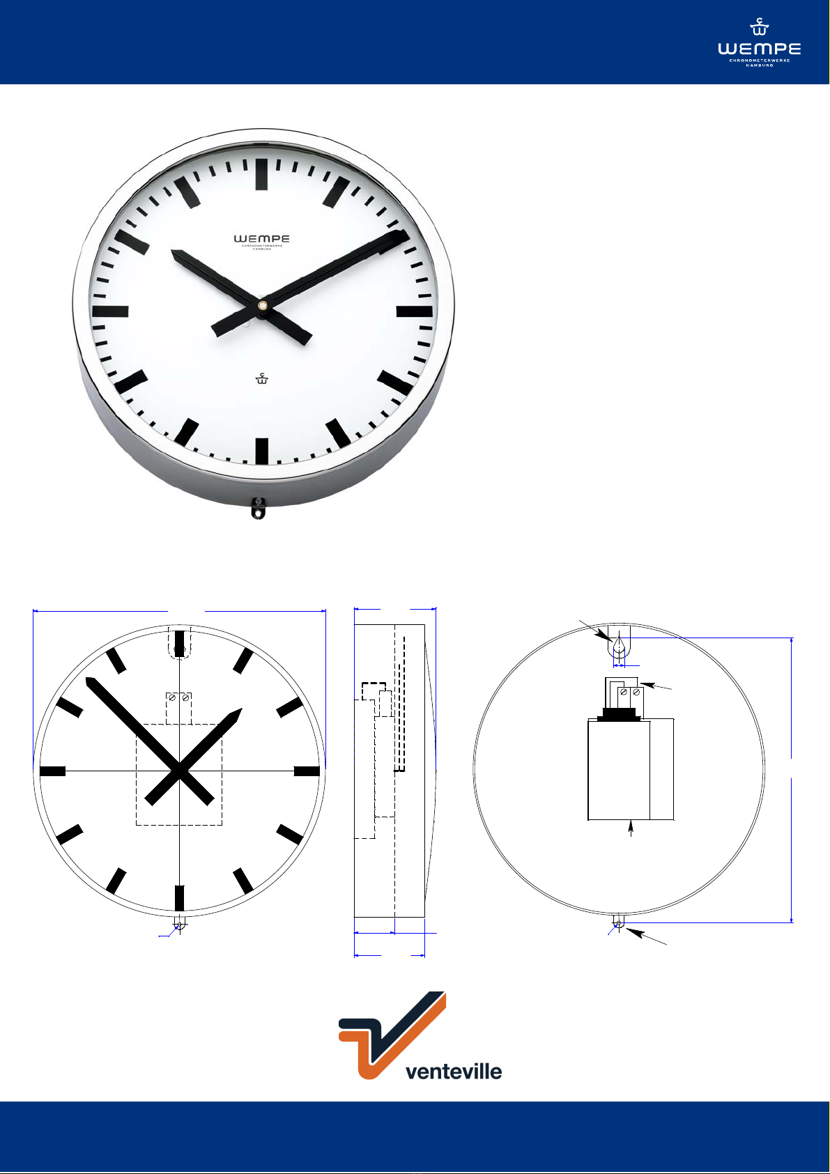
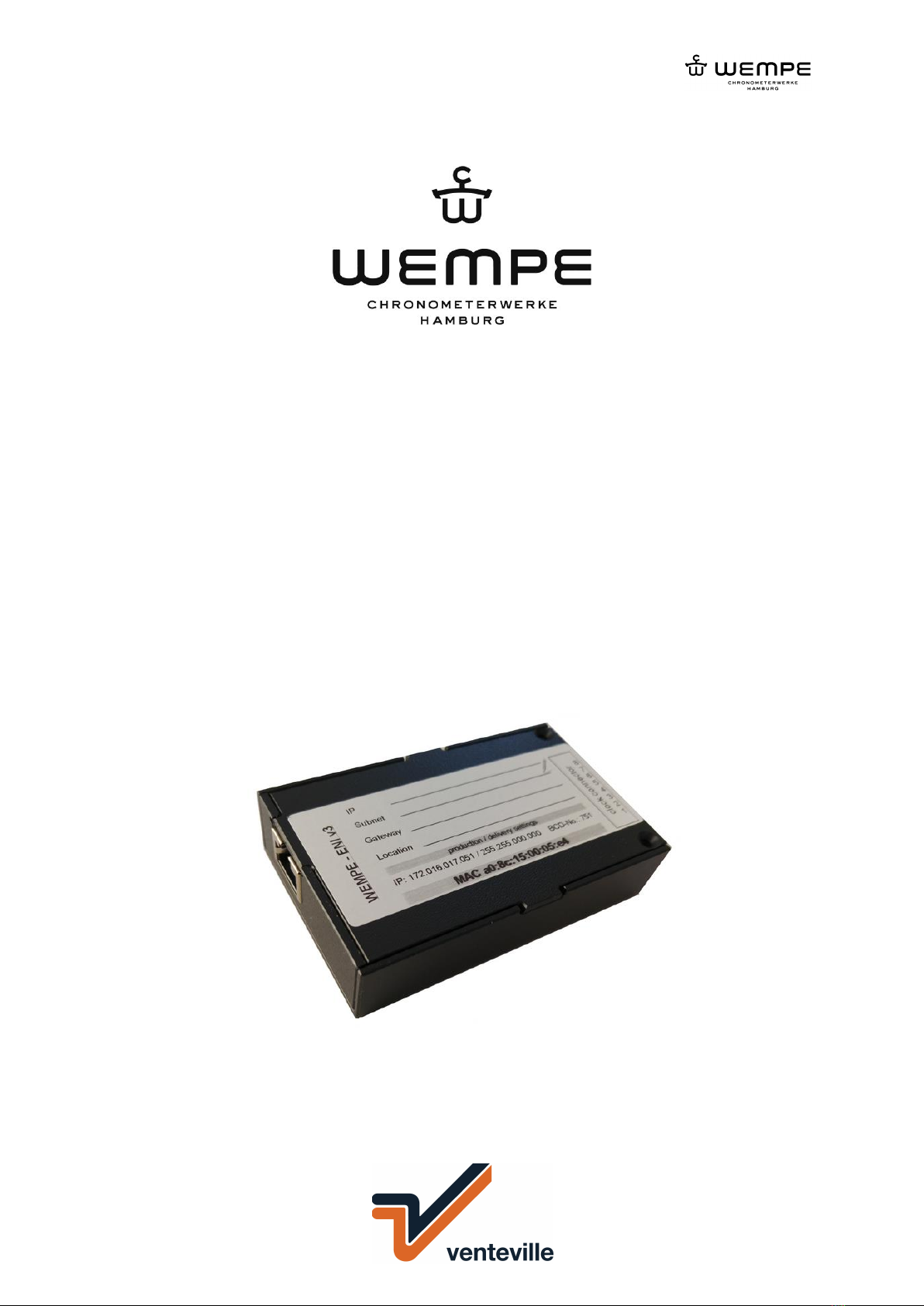
Schiffsuhr CHROM 232mm Mod. 20804/IP ENI v3
Marine clock CHROME 232mm Art.-no. CW850346
V0618
Assembly and commissioning instructions
for secondary clock movements’ type: T
This state-of-the-art secondary clock movement can run on
polarizing minute impulses of 12, 24, 48 or 60V DC. It is
suitable for indoor clocks as well as for outdoor clocks with
protected hands with a diameter of 80cm at maximum. The
movement is maintenance-free.
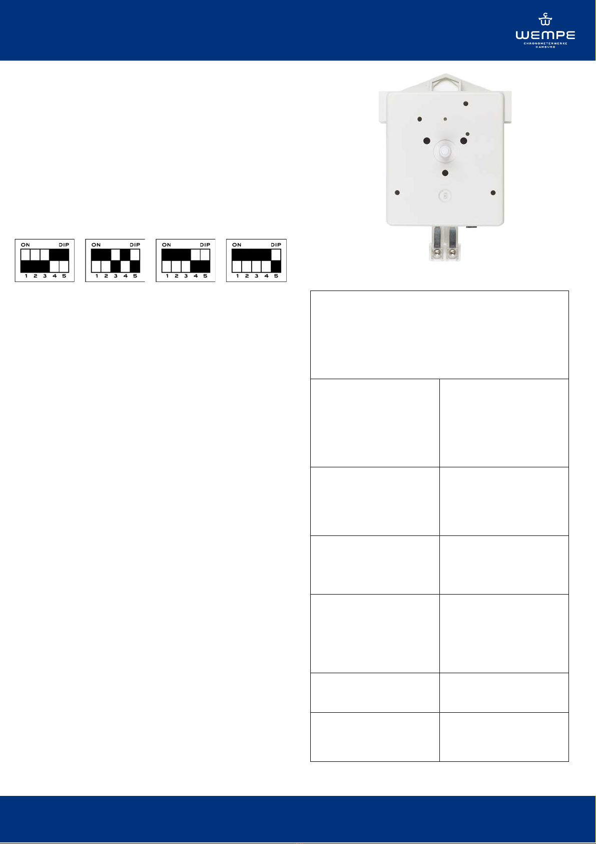
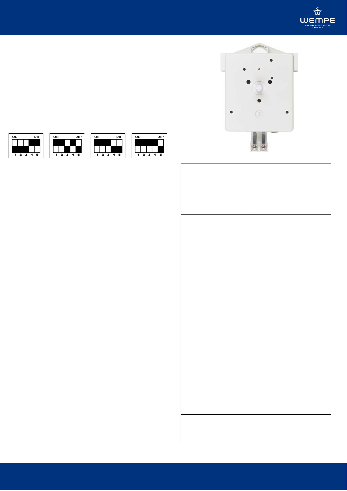
1. Operation voltage
The factory setting for the operation voltage is 24V DC.
Any other voltage can be set on the back of the movement
by means of a DIP-switch.
12V 24V 48V 60V
2. Clocks with a metal or plastic dial
Fix the movement to the dial with a 3-points fixation and
the enclosed pins (maximum thickness 3.5mm). There is
no particular operation position prescribed for the
secondary clock movement. Normally, the DIP-switch
should point downwards.
2.1 Clocks with transparent dials
The movement type TN-Lang has to be used for watches
with a dial made of acrylic glass (maximum thickness
12mm). The motion-work of this movement type is 36mm
long. Place the movement from the backside into the
centre hole of the dial with or without distance washers
(depending on the dial thickness), with the paperboard
washer and the rubber washer. Then place another rubber
washer from the front side on it and fix the movement by
means of the centre fixation screw.
3. Assembly of the hands
Place the hour hand on the hour arbour. If necessary, the
liner of the hand has to be slightly squeezed. Then place
the minute hand on the minute arbour and tighten the pin
screw M2 of the liner. Please pay attention that there is
enough space between the hands. To check this, turn the
minute hand until the clock is set to 12 o’clock. If the
hands are correctly fixed and adjusted, they are now one
on top of the other. If not, you have to adjust the hands
once again.
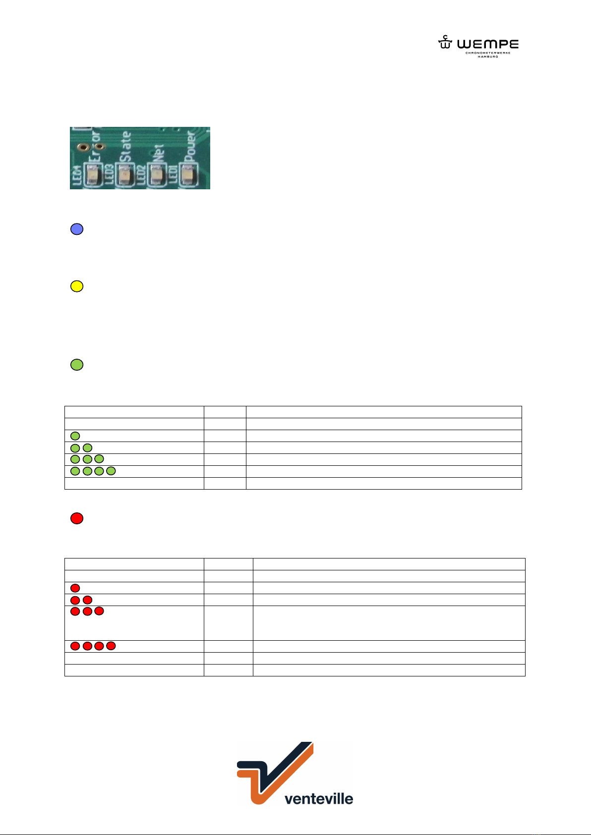
4. Connection to the power supply
Fix the master clock cables to the 2-poles plug. Should
there be a difference of one minute between the master
and secondary clock after putting the clocks into operation,
turn the 2-poles plug by 180°.
5. Setting of the hands
This can be done either manually by turning the minute
hand or by means of the setting bottom placed in a
countersink on the backside (using a screwdriver).
Technical data
Minutes slave clock movement type: T
up to 30 cm of dial diameter
for non-transparency dials
Planning information:
Electrical connection
For the operation and the transmitting of the minute impulse
is a two-wire line necessary.
Case
Width
Height
Height with SC in-series
adapter
Depth
Material
79,2 mm
92 mm
114 mm
21,5 mm
Synthetic material
Minute pointer shaft
Length from dial layer
Socket length
Diameter
Material
14 mm
4,4 mm
4 mm
Synthetic material
Hour pointer shaft
Length from dial layer
Diameter
Material
9 mm
6 mm
Synthetic material
Electrical values
Impulse-nominal voltage
Impulse current
Insulating resistance
Torque at Impulse-nominal
voltage
12, 24, 36, 48 ,60 Volt
12 mA at 12 V, otherwise 6
mA
800 Volt
150 cmp
Way of fastening
Three hole Spreading rivet, synthetic
material
Surrounding values
Protective system
Environmental temperature
Weight
IP 51
-25 °C to +70 °C
ca. 0,2 kg