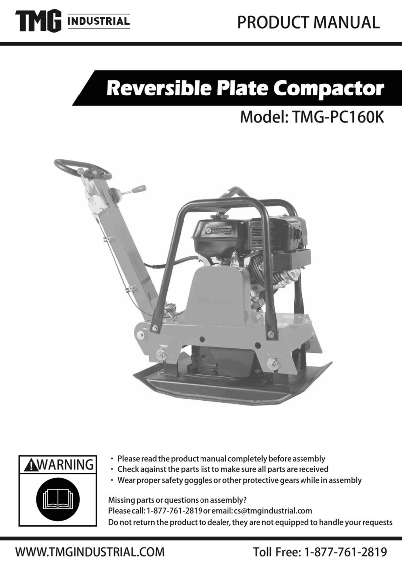
Wen 56035T User manual

This is a guide to greasing the vibrating assembly for your WEN 56035, 56035T, or 56035M
plate compactor This guide is best used in conjunction with the compactor’s manual, included
as a physical copy with your unit and available on the WEN website page for the plate
compactor (link here ), by clicking “Click here to view the product manual”
If at any point you need assistance, have questions, or want to order parts, call WEN customer
service at 1-847-429-9263, M-F, 8-5 Central Time, or email techsupport@wenproducts com
If replacing any parts, use only genuine replacement parts purchased from WEN Products. Use of replacement
parts not sold by WEN Products will void your warranty and could lead to decreased performance or injury.
ABLE OF CON EN S
Tools needed 1
Removing the vibrating assembly 1
Greasing the vibrating assembly 5
Reassembly 8
OOLS NEEDED
•13, 17, 18, 19, 27mm sockets and ratchet
◦Alternative: combination or adjustable
wrench(es)
•Impact wrench or breaker bar (optional)
•Large flat-head screwdriver
•Torque wrench and appropriate standard
sockets, as well as 5mm and 6mm hex-bit
sockets
•5mm and 6mm hex wrench
•Retaining ring pliers
•Rubber mallet
•Reversible anaerobic threadlocker (e g blue
Loctite ®)
•NLGI #2 EP lithium-based high-temperature
grease, approximately 60 – 70 grams
ENSURE THAT THE ENGINE IS COOL BEFORE BEGINNING ANY MAINTENANCE OR REPAIR WORK FOLLOW
ALL SAFETY PROCEDURES LISTED IN YOUR OWNER’S MANUAL USE COMMON SENSE AVOID INJURY
REMOVING HE VIBRA ING ASSEMBLY
1 Make sure the engine is shut down and fully cooled Drain the engine oil and gasoline according to the
instructions in your owner’s manual
2 Use a 13mm socket and ratchet (or combination wrenches) to remove the mounting bolts on both sides of the
belt cover (Figs 1 & 2)
Fig. 1: Mounting bolt 1. Fig. : Mounting bolt .
Date last modified: 0 3/01/30

3 Remove the belt cover The clutch and belt are now exposed (Fig 3)
4 With the screwdriver shaft positioned on the outside of the clutch, position the tip under the belt, and lever the
belt off the clutch while turning the clutch counterclockwise (Figs 4 & 5)
Fig. 4: Removing the belt (1).
Fig. 5: Removing the belt ( ).
Date last modified: 0 3/01/30
Fig. 3: Clutch and belt.

5 The belt can now be removed from the lower, vibrating assembly pulley (within the plate)
6 Remove the 4 nuts and washers from both sides of the engine support plate (Fig 6)
7 Gently lift the handles, engine assembly, and support plate off the shock absorbers, and carefully set the
assembly to the side
8 Remove the 8 mounting bolts from the exciter seat (Fig 7), then remove the exciter seat and vibrating
assembly from the bottom plate You may need an impact wrench or breaker bar to remove the bolts
Date last modified: 0 3/01/30
Fig. 7: Remove the 8 mounting bolts, then gently remove the exciter seat and vibrating
assembly from the bottom plate.
Fig. 6: Remove these nuts and washers ( each side).

9 Use the 27mm socket and adjustable or combination wrench to remove the two mounting bolts and nuts from
the vibrating assembly (Figs 8 & 9) You may need a breaker bar or impact wrench to remove the nuts and
bolts
Fig. 8: Remove these bolts (top of assembly). Fig. 9: Remove these nuts (bottom of assembly).
10 Remove the old vibrating assembly from the exciter seat (Fig 10)
Date last modified: 0 3/01/30
Fig. 10: Vibrating assembly removed.

GREASING HE VIBRA ING ASSEMBLY
11 Use the 6mm hex wrench to remove the socket-head cap screw and washers from the right side of the
vibrating assembly (Figs 11, 12) It’s a standard right-hand threaded screw (lefty-loosey)
Fig. 11: Use a 6mm hex wrench to remove this screw. Fig. 1 : Screw and washer removed.
12 Slide the pulley off the assembly, as well as the shaft key (Figs 13, 14)
Fig. 13: Pulley removed. Fig. 14: Shaft key removed.
13 Remove the retaining ring and eccentric block (Figs 15 – 17)
Date last modified: 0 3/01/30

Fig. 15: Retaining ring. Fig. 16: Retaining ring removed. Fig. 17: Eccentric block removed.
14 Use the 5mm hex wrench to remove the 3 socket-head cap screws around the bearing cover (Fig 18 – 19)
They are standard right-hand threaded screws (lefty-loosey)
Fig. 18: Remove 3 screws from bearing cover. Fig. 19: Screw removed.
15 Remove the bearing cover and oil seal (brown seal shown around the shaft in Fig 18 above) from the main
body You may need to clamp the main body to the table to do this It is easiest to gently twist the cover and
seal off the shaft; you can also gently use a flat-head screwdriver to help loosen it from the body Be careful
not to damage the bearing cover Once the bearing cover is removed (Fig 20), the bearing is exposed (Fig
21)
Date last modified: 0 3/01/30

Fig. 0: Bearing cover removed. Fig. 1: Bearing exposed.
16 Apply approximately 60 – 70 grams of high-temperature grease to the bearing Pack it in tightly
17 Replace the bearing cover and oil seal Apply some reversible anaerobic threadlocker (e g blue Loctite ®) to
the screw threads, then tighten them in a circular pattern Use the torque wrench to tighten the screws to 8.1
ft-lbs (11 Nm).
18 On the other side of the assembly, remove the retaining ring, eccentric block, and bearing cover and oil seal
(basically, repeat steps 13 – 15) Apply approximately 60 – 70 grams of high-temperature grease to the
bearing Pack it in tightly
19 Replace the bearing cover and oil seal Apply some reversible anaerobic threadlocker (e g blue Loctite ®) to
the screw threads, then tighten them in a circular pattern Use the torque wrench to tighten the screws to 8.1
ft-lbs (11 Nm).
20 Reassemble the eccentric blocks and retaining rings on both sides
21 Replace the pulley and shaft key (step 12)
22 Apply some reversible anaerobic threadlocker (e g blue Loctite ®) to the pulley mounting screw threads, and
use the torque wrench to tighten the pulley mounting screw and washer (step 11) to 19.2 ft-lbs (26 Nm).
23 The vibrating assembly is now fully greased and ready to be reassembled onto the plate compactor
Date last modified: 0 3/01/30

REASSEMBLY
24 Position the vibrating assembly on the exciter seat When reinstalling the mounting nuts and bolts, apply some
reversible anaerobic threadlocker (e g blue Loctite ®) to the bolt threads, and use the torque wrench to
tighten the nuts to 147.5 ft-lbs (200 Nm)
25 Reinstall the exciter seat and vibrating assembly on the bottom plate When reinstalling the mounting bolts,
apply some threadlocker to the bolt threads, and use the torque wrench to tighten the nuts to 60.5 ft-lbs (82
Nm)
26 Reposition the engine assembly and support plate on the shock absorbers Thread the belt through the slot in
the support plate Tip the engine assembly up and install the belt on the clutch pulley (see Fig 4) Tip the
assembly down and use a socket or wrench to tighten the lock nuts removed in step 6
1 TIP: if you’re having trouble using this technique, use the screwdriver technique (step 4 ) to work the belt
back onto the pulley
27 Replace the belt cover and mounting bolts When reinstalling the mounting bolts, apply some threadlocker to
the bolt threads, and use the torque wrench to tighten the bolts to 20.6 ft-lbs (28 Nm)
28 Reinstall the handles and all mounting nuts and bolts Use a socket or wrench to tighten them
29 Make sure all fasteners are fully tightened Start your plate compactor according to the instructions in your
manual
QUES IONS? PROBLEMS?
Contact WEN Customer Service at 1-847-429-9263, M-F, 8-5 CST, or email
techsupport@wenproducts com
Date last modified: 0 3/01/30
Other manuals for 56035T
2
This manual suits for next models
2
Table of contents
Other Wen Vibratory Rammer & Tamper manuals
Popular Vibratory Rammer & Tamper manuals by other brands

Fayat
Fayat Dynapac CC900G instruction manual

Masalta
Masalta MR70H instruction manual

Scheppach
Scheppach VS1000 Translation from the original instruction manual

Ammann
Ammann APR 2220 operating instructions

Enarco
Enarco AVMU-AX25 instruction manual

MULTIQUIP
MULTIQUIP Mikasa MTX-90 Operation and parts manual