Wenger Diva Acoustical Tower User manual

Installation Instructions
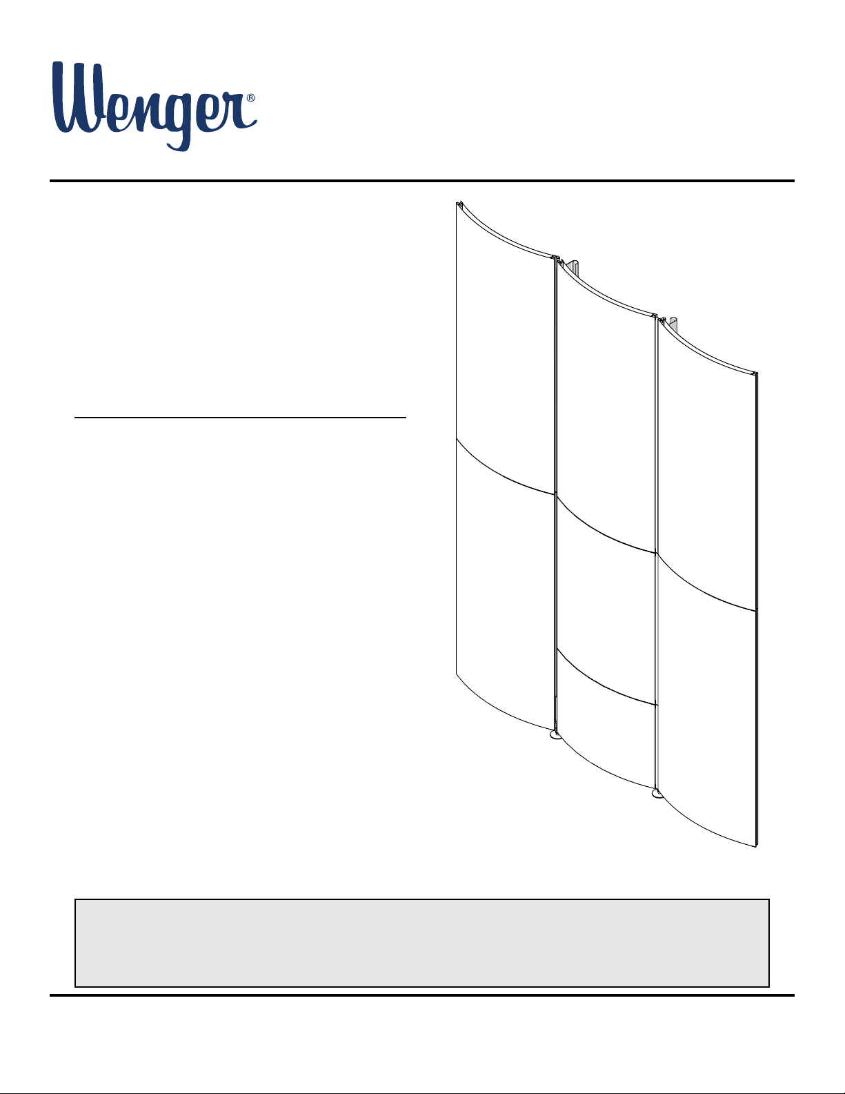
Diva
®
Acoustical Tower
©Wenger Corporation 2020 Printed in USA 2020-02 Part #185C755-05
Wenger Corporation, 555 Park Drive, P.O. Box 448, Owatonna, Minnesota 55060-0448
Questions? Call.....USA: (800) 4WENGER (493-6437) • Worldwide: +1-507-455-4100 • wengercorp.com
Contents
Note: Please read and understand these instructions before installing.
Note: Review all of the Installation Drawings and Reference Drawings.
Note: Three or more people are recommended to work together during assembly and installation.
Note: If you need additional information, contact Wenger Corporation using the information below.
Important User Information . . . . . . . . . . . . . . . . . . . . . . . . . . . . . . 2
General . . . . . . . . . . . . . . . . . . . . . . . . . . . . . . . . . . . . . . . . . 2
Manufacturer ....................................2
Intended Use ....................................2
Installation ......................................2
Warranty ........................................2
Safety Precautions . . . . . . . . . . . . . . . . . . . . . . . . . . . . . . . . . . . . 3
Before Installation . . . . . . . . . . . . . . . . . . . . . . . . . . . . . . . . . . . . . 3
Required Tools. . . . . . . . . . . . . . . . . . . . . . . . . . . . . . . . . . . . . . . . 3
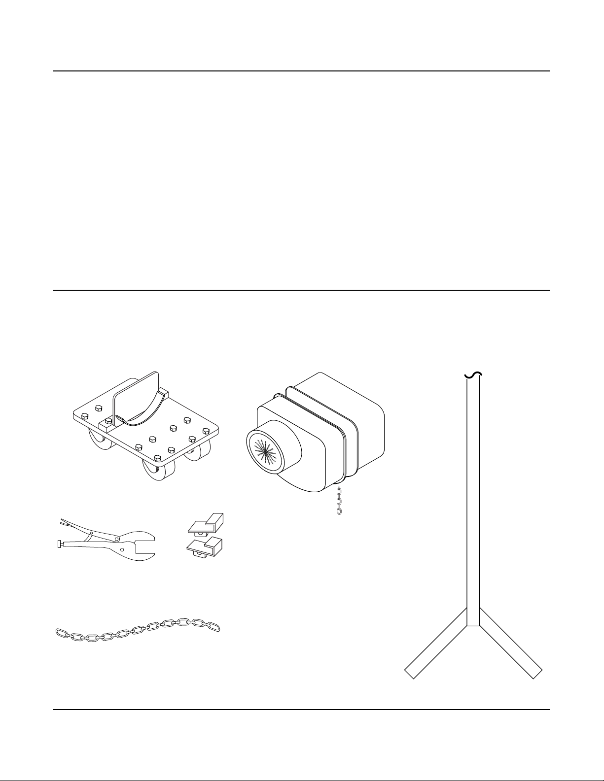
Rigging Equipment . . . . . . . . . . . . . . . . . . . . . . . . . . . . . . . . . . . . 4
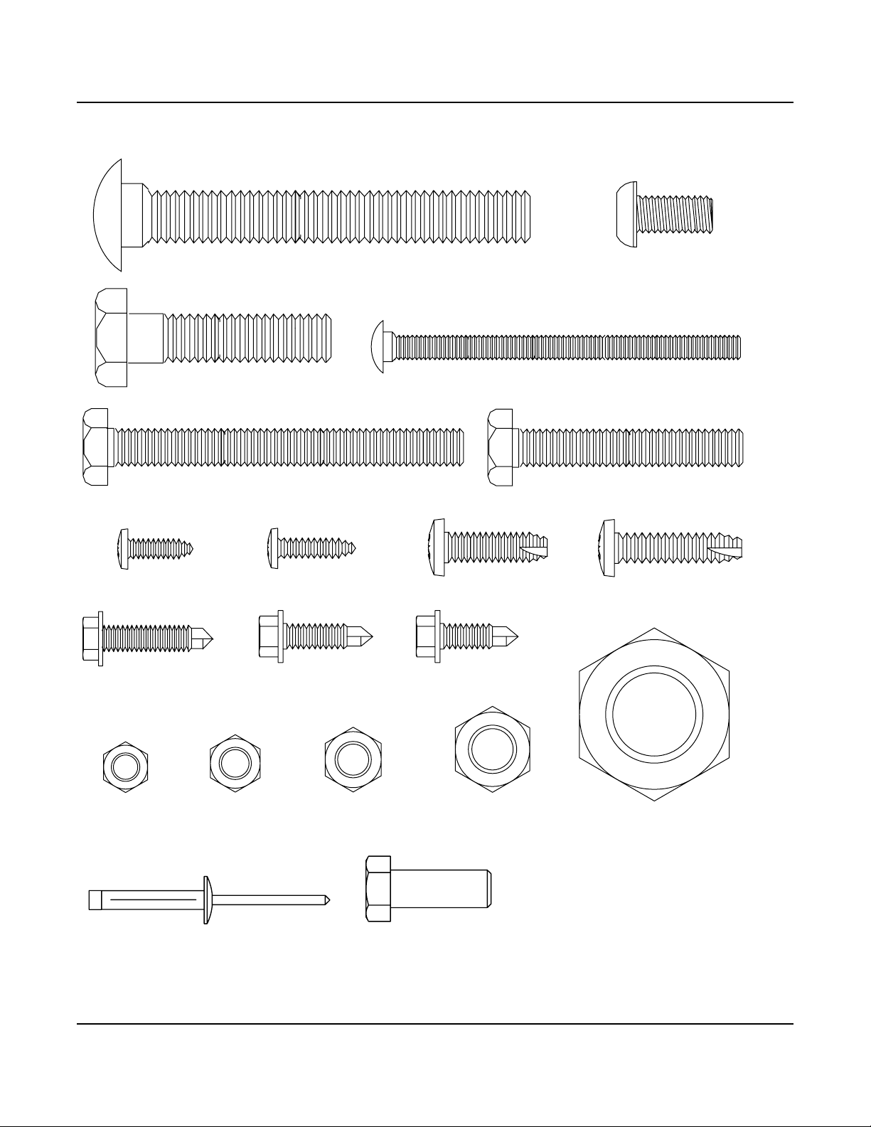
Fasteners. . . . . . . . . . . . . . . . . . . . . . . . . . . . . . . . . . . . . . . . . . . . 5
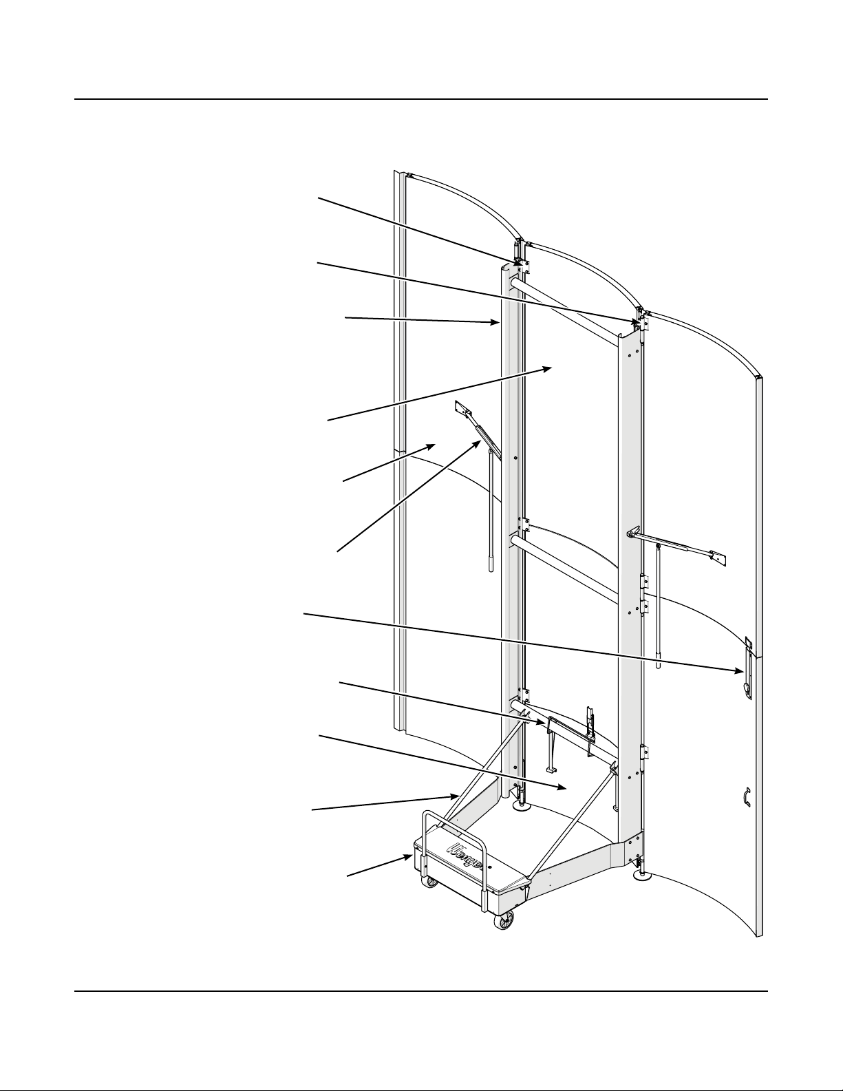
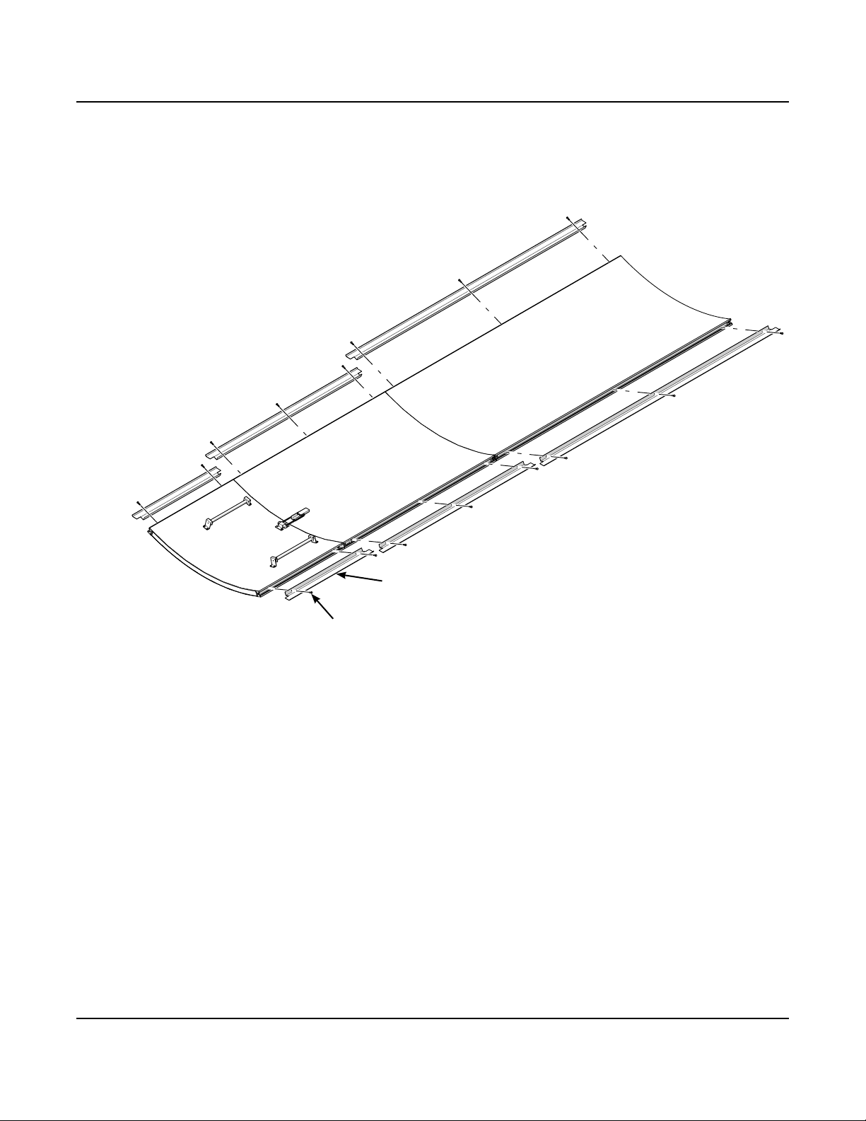
Tower Assembly Description . . . . . . . . . . . . . . . . . . . . . . . . . . . . . 6
Tower Installation . . . . . . . . . . . . . . . . . . . . . . . . . . . . . . . . . . . . . 7
Assemble the Tower Frame .........................7
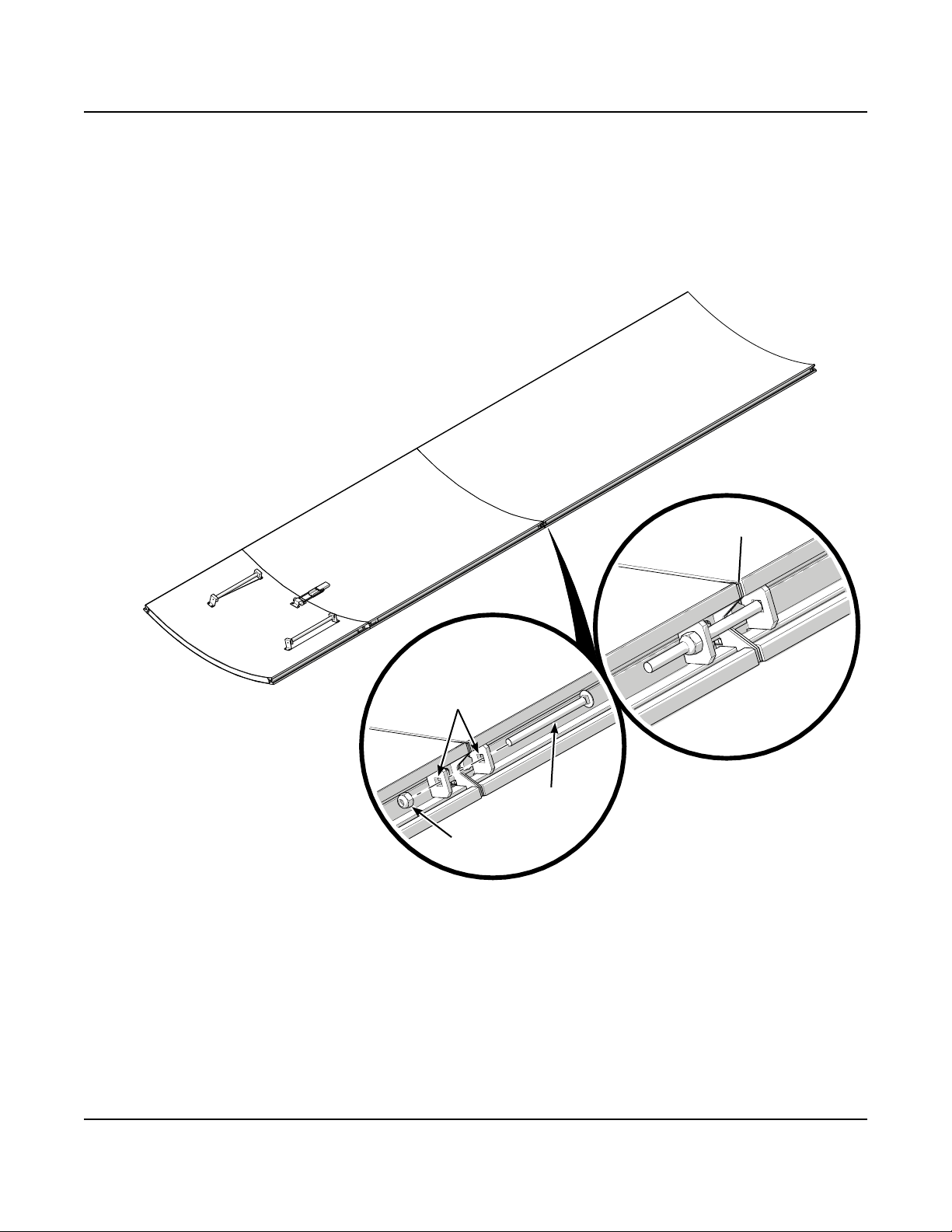
Assemble the Center Panels ........................8
Attach Trim to the Center Panels .....................10
Separate Lower Filler Panel .........................11
Attach Frame to the Center Panels ...................12
Attach Base .....................................14
Attach Wing Panels ...............................16
Attach Leveler Assembly ...........................18
Attach Wing Stays ................................19
Attach Slide Lock .................................21
Attach Door Pull Handle ............................22
Lifting Tower .....................................23
Install Counterweights .............................25
Attach Base Handle ...............................26
Store Lower Filler Panel ............................27
Attach Lower Filler Panel ...........................28
Moving Towers ...................................29
Decals, Numbers and Logos . . . . . . . . . . . . . . . . . . . . . . . . . . . . 32
Final Inspection . . . . . . . . . . . . . . . . . . . . . . . . . . . . . . . . . . . . . . 32
Visit the Diva Acoustical Shell web page at wengercorp.com for more information.

2
Important User Information
General
Copyright © 2020 by Wenger Corporation
All rights reserved. No part of the contents of this manual may be reproduced, copied, or transmitted in any form
or by any means including graphic, electronic, or mechanical methods or photocopying, recording, or information
storage and retrieval systems without the written permission of the publisher, unless it is for the purchaser's
personal use.
Printed and bound in the United States of America.
The information in this manual is subject to change without notice and does not represent a commitment on the
part of Wenger Corporation. Wenger Corporation does not assume any responsibility for any errors that may
appear in these instructions.
In no event will Wenger Corporation be liable for technical or editorial omissions made herein, nor for direct,
indirect, special, incidental, or consequential damages resulting from the use or defect of these instructions.
The manufacturer reserves the right to change this product at any time.
The information in this document is not intended to cover all possible conditions and situations that might occur.
The end user must exercise caution and common sense when assembling or installing Wenger Corporation
products. If any questions or problems arise, call the Wenger Corporation at (800) 4WENGER (493-6437)
or +1-507-455-4100 worldwide.
Manufacturer
The Diva®Acoustical Tower is manufactured by:
Wenger Corporation
555 Park Drive
Owatonna, MN 55060
(800) 4WENGER (493-6437) • +1 (507) 455-4100
wengercorp.com
Intended Use
• The tower is intended for indoor use only and is not intended for outdoor use.
• Never expose the tower components to wind, humidity, or wet conditions.
• This product is intended to be assembled only as described in these instructions.
Installation
• The tower installation and use must comply with local regulations and codes.
• All personnel (including all temporary workers) installing or maintaining the tower must read and
understand these and other related installation instructions.
Warranty
This product is guaranteed free of defects in materials and workmanship for ve full years from date
of shipment. A full warranty statement is available upon request.

3
Make sure that anyone working
with the Diva Acoustical Tower
has read and understands these
instructions.
Always observe and comply
with the Warnings and
Cautions posted on the system
equipment.
Failure to comply with Warnings
and Cautions in this document
can result in damage to property
or serious injury.
Safety Precautions
Throughout this document you may nd cautions and warnings which are dened as follows:
• WARNING: Failure to follow the instruction could result in serious injury or damage to property.
• CAUTION: Failure to follow the instruction could result in minor injury or damage to property.
Read all of these safety instructions before using the equipment.
Components can be heavy or
dicult to handle and may require
three or more people working
together to lift or assemble.
To avoid damage to tower surfaces:
• Always wear gloves during assembly and installation.
• Lay any nished surfaces onto the cardboard and
foam packaging to help protect from damage.
• During assembly, dropped hardware can roll under
other components and cause damage to nished
surfaces.
Before Installation
1. Read and understand the entire tower installation section before starting the installation.
2. Make sure that all personnel installing (including any temporary workers) are trained and understand
the installation procedure.
3. Review all installation drawings and reference drawings.
Save these drawings for future reference.
4. Make sure that all items on the shipment packing list are present.
Note: These instructions describe typical assembly and installation of 16' (4877 mm) tall towers.
Towers taller than 24' (7315 mm) require frame extensions as explained in these instructions.
All Diva Acoustical Shells are installed in the same way.
!CAUTION
!WARNING
!WARNING
!WARNING
!CAUTION

4
The following tools are required for assembly.
• Assorted wrenches
• Cordless drill and cordless impact driver
• 3/8", 7/16", 1/2" and 9/16" hex nut bit
• 3/8" drift pin
• Mallet
• 24" carpenters' square
• 9/32" and 25/64" drill bit
• Chalk line
• Box level
• C-clamp set
• Phillips screwdriver
• Hex wrench set
• 3/8", 1/2" and 3/4" drive sockets
• 7/16" deep well socket and drive adapter
with a universal
• Ratchet
• Angle nder
• 100" measuring tapes (2)
• 25' tape rule
• Claw hammer
• Caulk gun
• Rivet gun
*Save the wood blocks from the tower frame and ceiling truss packaging.
They will be used later during the tower assembly.
Required Tools
Wing
Harnesses
Span Set Slings
Lifting Casters
Locking Clamps
1-ton Invertible Hoist
• Lifting casters
• Locking clamps
• Chain
• Wing harnesses
• Span set slings
• 1-ton invertible hoist
Rigging Equipment
The installers must supply the following rigging equipment for the tower installation.
Chain

5
Fasteners
The fasteners shown below are contained in various Diva hardware kits.
Any fasteners remaining when an the installation is complete can be discarded.
Button Head Screw,
3/8-16 x 1"
Carriage Bolt, 1/4-20 x 3-1/2"
Screw, Self-drill,
1/4-14 x 3/4"
Hex Head Screw, 3/8-16 x 3-1/2"
Lock Nut,
1/4-20
Lock Nut,
1/2-13
Lock Nut,
3/8-16
Hex nut,
5/16-18
Tapping Screw,
5/6 x 1"
Carriage Bolt, 1/2-13 x 4"
Screw, Pan Head,
10-24 x 5/8"
Screw, Self-drill,
1/4-20 x 1-1/4"
Hex Jam Nut,
1-8
Hex Head Screw,
3/8-16 x 2-1/4"
Tapping Screw,
1/4-20 x 1/2"
Screw, Sheet Metal,
10-18 x 3/4"
Hex Head Screw, 1/2-13 x 2"
Screw, Self-drill,
1/4-20 x 1"
Rivet, Blind, Tri-Fold,
0.19 Dia
Capscrew,
3/8-16 x 1"

6
Tower Assembly Description
The following illustration describes components used in the Diva Acoustical Tower Assembly.
Lower Filler Panel — Panel that can be
removed and stored to allow nesting to
other tower assemblies for storage.
Wing Panel — Outside sets of panels that
pivot for storage. The lower panel may be
congured as a door.
Vertical Frame — Frame consisting of two
vertical uprights and three or more cross
braces. The vertical uprights have xed and
rotating hinges that attach the wing panels
and center panels.
Center Panels — Set of panels that are
xed at the center of the assembly.
Wing Stay — Locks the wing panel in the
storage position or performance position.
Fixed Hinge — Bracket that is used to attach
the center panels to the vertical frame.
Rotating Hinge — Rotating hinge that
connects the wing panels to the center
panels.
Weldment Bar — Bracket that holds the
lower ller panel when the tower is stored.
Diagonal Brace — Structural member
adding stability to the tower assembly
and a means to adjust the tower plumb.
Counterweighted Frame — Base that
supports the vertical structure and balances
the tower assembly.
Slide Lock — Locks the wing panel
to the door panel.

7
Tower Installation
The following procedure is described using a 16' (4877 mm) tall Diva Tower.
Taller towers are assembled using the same steps but may need to be spliced together.
Refer to the installation drawings.
Assemble the Tower Frame
1. Assemble the tower frame as shown.
a. Layout both the left and right hand vertical tower frames with the at side of each frame facing
toward the outside.
b. Position the lower cross brace with the weldment bar facing toward the top and align with the third set
of holes in the frames.
c. Position the upper cross braces to align with the next set of holes in the frames and then approximately
every 8' (2438 mm) thereafter.
d. Attach all of the cross braces to both tower frames using two 3/8-16 x 0.750 hex head capscrews
in each side.
The capscrews attach directly to a welded nut on the inside of the cross braces.
2. Set the tower frame assembly aside to attach later.
Right Hand
Vertical
Tower Frame
Left Hand
Vertical
Tower Frame
Cross
Brace
Lower
Cross Brace
3/8-16 x 0.750
Hex Head
Cap Screw
Weldment bar faces
toward the top
Bottom two sets
of holes for the
base
Set of holes
for wing stay

8
Tower Installation (continued)
Assemble the Center Panels
Refer to the installation drawings for center panel placement.
1. Sweep the oor around the assembly area and place the sheets of cardboard that shipped with the
tower onto the oor surface to protect the panel surfaces.
2. Place the center panels with the nished surface facing down onto the cardboard and remove the tape
holding any protective paper to the face of the panels.
3. Cut foam strips to span the entire width of each upper center panel and install it to be fully recessed into
the bottom edge of the panel.
Then trim each foam strip end to a 45° angle.
Upper Center
Panel
Lower Center
Panel
Sheets of
Cardboard
Foam strip
location Cut foam strip
edges to 45°
angles
Foam Strip
Lower Filler
Panel
Handle
3/16"
Blind Rivets
Orient panel so part number
labels are at the bottom
4. Attach two handles to the lower ller panel using
3/16" blind rivets in each of the pilot holes.

9
Tower Installation (continued)
Assemble the Center Panels (continued)
5. Connect the upper center panel and lower center panel together.
a. Slide the panels together and align the edges.
b. Connect the two panel inner clips together using a 1/4-20 x 3-1/2" carriage bolt and 1/4-20 lock nut.
Tighten until just snug.
c. Repeat to connect the panels on the other side.
Panel Inner
Clips
1/4-20 x 3-1/2"
Carriage Bolt
1/4-20
Lock Nut
Clips should
be touching

10
Attach Trim to the Center Panels
1. Align trim strips of matching lengths to both sides of all of the center panels.
The ends of the trim strips should match with the gaps between the panels.
2. Attach the trim strips to the panels using 1/4-20 x 1" self-drilling screws as shown.
Tower Installation (continued)
Trim
Strip
1/4-20 x 1"
Self-drilling Screw

11
Separate Lower Filler Panel
1. Separate the lower ller panel from the lower center panel by removing the bracket and two screws
that secure each side.
2. Flip the hasp up to release the hook.
3. Slide the lower ller panel away and set it aside.
Tower Installation (continued)
Lower Filler
Panel Bracket
Screws
Flip hasp up

12
Tower Installation (continued)
Attach Frame to the Center Panels
1. Place the tower frame assembly onto the center panels.
Position the weldment bar on the frame assembly to be near the door latch on the lower panel.
Be sure not to trap the hinges of the tower frame inside of the trim at the edges of the center panels.
Do not attach the frame to the center panels yet.
Position the weldment bar
near the door latch
Be sure not to trap the
hinges inside of the trim

13
Tower Installation (continued)
Attach Frame to the Center Panels (continued)
2. Place wood blocks (that were saved from the packaging) under both sides of the frame assembly
to hold it steady and to keep pressure o of the panels.
The wood blocks must be at even heights on both sides and positioned to not extend beyond the edge
of the frame as shown.
3. Align the frame assembly and the center panels: Proper alignment is critical!
a. Set the distance between the bottom of the lower center panel and the bottom of the frame assembly
to be 28-5/8" (727 mm) on both sides.
This is a critical measurement!
b. The seam between the center panels should be at the center of the middle xed hinge.
4. Attach the xed hinges to the center panels.
a. With the center panels in position and square to the tower frame using a 9/32" drill bit, drill a hole
through the inside panel surface only into each panel at each marked location.
Do not drill through the panel surface on the other side.
b. Clean away any wood shavings from drilling.
c. Attach the xed hinges to the center panels using 5/16-18 x 1" hex head tapping screws in the
sequence shown below.
5/16-18 x 1"
Hex Head
Tapping Screws
Seam between panels is
centered on middle hinge
28-5/8" (727 mm)
from bottom of
lower center panel
to bottom of
frame assembly
Tighten
1st
Position the wood blocks
to not extend beyond the
edge of the frame
28-5/8" (727 mm)
from bottom of
lower center panel
to bottom of
frame assembly
Do not over tighten the screws,
damage to the panels could result.
Drill through the upper panel surface only.
Do not drill through the lower panel surface
on the other side.
!CAUTION !CAUTION
Drill through the upper
panel surface only.
Do not drill through the
lower panel surface.
Tighten
2nd
Tighten
3rd
Tighten
4th
Tighten
5th
Tighten
6th

14
Tower Installation (continued)
Attach Base
1. Attach the base assembly to the bottom of the tower frame using four 3/8-16 x 1" capscrews and
3/8-16 lock nuts on each side.
Only hand tighten the fasteners at this time.
3/8-16 x 1"
Capscrews
3/8-16
Lock Nuts
1-8 Hex
Jam Nut
Base
Rod
5"
(127 mm)
3"
(76 mm)
2. Attach a 1-8 hex jam nut to each end of both base rods.
Turn the nut to be at least 3" (76 mm) in from one end and 5" (127 mm)
in from the other end.

15
Tower Installation (continued)
Attach Base (continued)
3. Attach the brace rods.
a. Slide a brace rod into the base and
then into the lower cross brace
as shown.
b. Attach the brace rod using one 1-8 hex jam nut
at each end.
Square the base to the tower while
tightening the hex jam nuts.
c. Repeat for the other brace rod on the
other side.
Brace
Rod
First, slide brace rod
through the base
Then through the
lower cross brace
1-8 Hex
Jam Nuts
1-8 hex
jam nuts
on
both sides
1-8 Hex
Jam Nuts
Square the base to
the frame while
tightening the nuts

16
Attach Wing Panels
Refer to the installation drawings for wing panel placement.
1. Sweep the oor around the assembly area and place sheets of cardboard that shipped with the tower
onto the oor surface to protect the panel surfaces.
2. Place the wing with the nished surface facing down onto the cardboard and remove the tape holding
any protective paper to the face of the panels.
Orient the panels so the part number label is at the bottom.
Steps 3 and 4 are for non-access door wing panels only!
Wing panels that are access doors already have foam strips installed in the panels.
Wing panels that are not access doors will require foam strips to be cut and installed between the panels.
3. Cut a foam strip to span the entire width of the upper center panel and install it to be fully recessed into
the bottom edge of the panel.
4. Connect the upper and lower wing panels together.
a. Slide the panels together and align the edges.
b. Connect the two panel inner clips together using a 1/4-20 x 3-1/2" carriage bolt and 1/4-20 lock nut.
Tighten until just snug.
c. Repeat to connect the panels on the other side.
Tower Installation (continued)
Non-Access Door
Wing Panel
Orient panel so part number
labels are at the bottom
Panel Inner
Clips
1/4-20 x 3-1/2"
Carriage Bolt
1/4-20
Lock Nut
Clips
should be
touching
Sheets of
Cardboard
Foam
Strip
Access Door
Wing Panel

17
Attach Wing Panels (continued)
5. Align the seam of the adjacent wing panels with the seam of the center panels.
The panels should also be aligned along the top edge.
6. Attach the wing panels to the tower frame.
a. With the wing panels in position and square to the tower frame using a 9/32" drill bit, drill a hole
through the inside panel surface only into each panel at each marked location.
Do not drill through the panel surface on the other side.
b. Clean away any wood shavings from drilling.
c. Attach the wing panels to the rotating hinges using 5/16-18 x 1" hex head tapping screws.
7. Attach trim to the outer edges of the wing panels as indicated on the installation drawings.
Tower Installation (continued)
Do not over tighten the screws,
damage to the panels could result.
Drill through the upper panel surface only.
Do not drill through the lower panel surface
on the other side.
!CAUTION !CAUTION
5/16-18 x 1"
Tapping Screws
5/16-18 x 1"
Tapping Screws
Align
seams
Drill through the upper panel surface only.
Do not drill through the lower panel surface.
Align
tops
Trim
Strip
Trim
Strip

18
Attach Leveler Assembly
1. Attach the two leveler assemblies to the bottom of the base.
a. Turn the 1-8 hex jam nut on both leveler assemblies to be at the same height.
b. Turn each leveler assembly onto the base until the jam nut contacts the bottom of the base.
c. Adjust the leveler assembly so that the distance between the bottom of the wing panel and the
bottom of the leveler pad is 2" (51 mm).
Tower Installation (continued)
Leveler
Assembly
1-8 Hex
Jam Nut
2" (51 mm)
Bottom of Panel
to Bottom of Pad

19
Attach Wing Stays
1. Assemble both the right and left wing stays.
a. Remove the capscrew from the top slot
in both wing stay channels.
b. The wing stays must be fully
extended as shown.
c. Screw a wing stay tube into the
bottom of the wing stay channel
until it is hand tight.
Tower Installation (continued)
2. On the outside of both frame side, attach one wing stay base bracket using
two 3/8-16 x 3/4" button head screws and 3/8-16 nylon insert lock nuts.
Wing Stay
Base Bracket
Wing Stay
Base Bracket
3/8-16 x 3/4"
Button Head
Screw
3/8-16 Nylon
Insert Lock Nut
Remove
Capscrew
Wing Stay
Tube
Wing Stay
Channel
(fully extended)
Wing Stay
Channel
(fully extended)
3/8-16 x 3/4"
Button Head
Screw
3/8-16 Nylon
Insert Lock Nut

4. Attach both wing stays to the wing panels.
a. Twist the wing stay tube
to loosen and fully extend
the wing stay.
b. With the wing stay fully
extended, place the
wing stay plate onto the
inside of the wing panel.
c. Apply adhesive to the
underside of the
wing stay plate and
reposition it.
d. Attach the wing stay plate
to the wing panel
using four 0.19 dia
tri-fold blind rivets.
20
Attach Wing Stays (continued)
3. Attach both wing stay assemblies to the wing stay
base bracket on each side using one
5/16-18 x 1-3/8" capscrew and
5/16-18 nylon insert lock nut.
Tower Installation (continued)
5/16-18 x 1-3/8"
Capscrew
5/16-18
Nylon Insert
Lock Nut
0.19 Dia
Tri-Fold
Blind Rivets
Wing Stay
Plate
Table of contents
Other Wenger Desktop manuals
Popular Desktop manuals by other brands

Gateway
Gateway DX441 Starter Guide

AXIOMTEK
AXIOMTEK GOT3187W-832-PCT user manual

ROCWARE
ROCWARE RP1S user manual

Studio Designs
Studio Designs Master's Touch Art & Craft Station manual

HP
HP ProDesk 405 G4 Small Form Factor Maintenance and service guide

Dell
Dell Precision 3431 Small Form Factor Setup and specifications guide

Sony
Sony PCG-SRX87 VAIO User Guide (primary manual) quick start

HP
HP Pavilion t600 - Desktop PC Product specifications

Cooler Master
Cooler Master CMStorm Trooper user manual

Xi Computer Corporation
Xi Computer Corporation MTower user guide

Lenovo
Lenovo V50s user guide

Lenovo
Lenovo ThinkCentre M75q user guide