Assembly Instructions
ourmaster
®
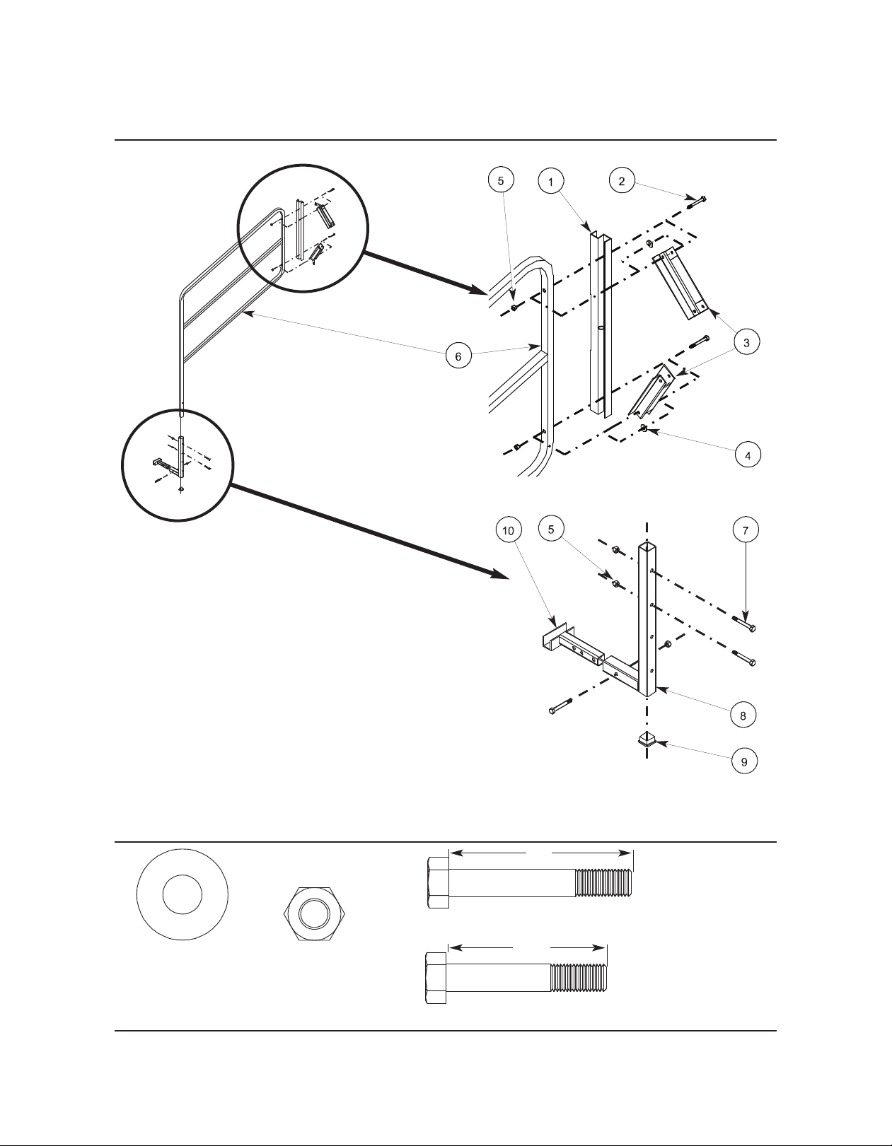
Side Rails
Parts List . . . . . . . . . . . . . . . . . . . . . . . . . . . . . . . . . . . . . . . . . . . . . . . . . . . . . . . . . . . . . . . . . . . . . . . . .2
Fasteners . . . . . . . . . . . . . . . . . . . . . . . . . . . . . . . . . . . . . . . . . . . . . . . . . . . . . . . . . . . . . . . . . . . . . . . .2
Side Rail Assembly . . . . . . . . . . . . . . . . . . . . . . . . . . . . . . . . . . . . . . . . . . . . . . . . . . . . . . . . . . . . . . . . .3
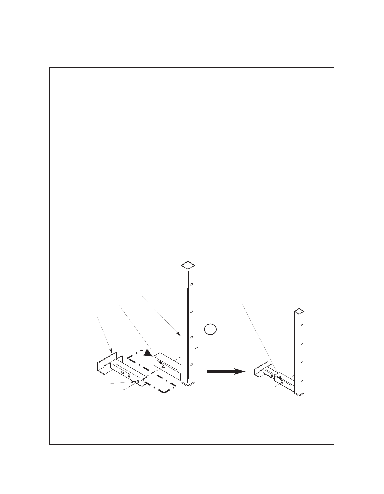
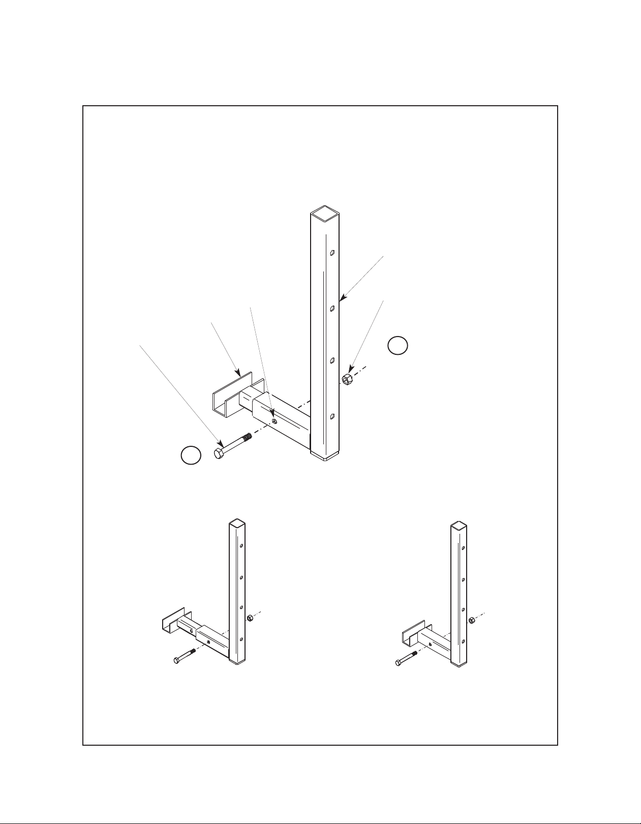
Assemble Slide Leg To Side Rail Leg . . . . . . . . . . . . . . . . . . . . . . . . . . . . . . . . . . . . . . . . . . . . . . . . .3
Assemble Side Rail Legs For All Risers With a 4th Step Addition . . . . . . . . . . . . . . . . . . . . . . . . . . .6
Assemble Side Rail Legs For All Risers Without a 4th Step Addition . . . . . . . . . . . . . . . . . . . . . . . . .7
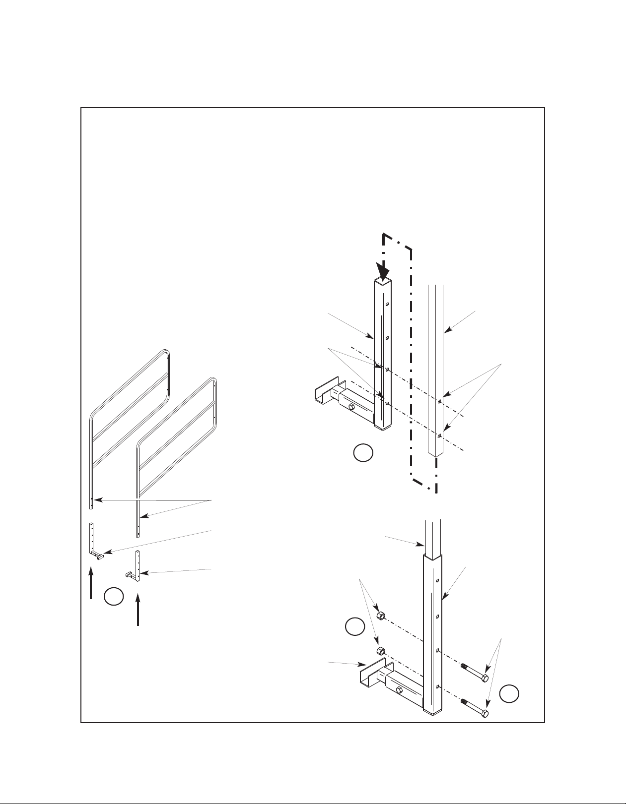
Assemble The Side Rail Brackets To the Side Rails . . . . . . . . . . . . . . . . . . . . . . . . . . . . . . . . . . . . .8
Assemble The Swing Brackets To The Side Rails . . . . . . . . . . . . . . . . . . . . . . . . . . . . . . . . . . . . . . .9
To Attach Side Rails To The Riser . . . . . . . . . . . . . . . . . . . . . . . . . . . . . . . . . . . . . . . . . . . . . . . . . . . . . .10
Note: Side Rails will fit on both the 3-step and 4-step Tourmaster Choral Risers.
Note: Please read and understand the Tourmaster Side Rail Assembly Instruction before
assembling the Side Rails parts.
Note: Remove all items from the shipping carton and arrange them in their approximate final
position. Refer to the illustrations on the following pages. If you need additional information,
contact the Wenger Corporation using the information below.
3-Step Model shown with optional
Side and Back Rails
CONTENTS
©Wenger Corporation 2014 Printed in USA 01/14 Part #024F148-05
Wenger Corporation, 555 Park Drive, P.O. Box 448, Owatonna, innesota 55060-0448
Questions? Call.....USA: 800-4WENGER (493-6437) • Worldwide: 1-507-455-4100 • www.wengercorp.com
Visit the Tourmaster Choral Risers
web page at www.wengercorp.com for detailed instructions and videos.