Wenger Diva User manual

Important User Information . . . . . . . . . . . . . . . . . . . . . . . . . . . . . . 2
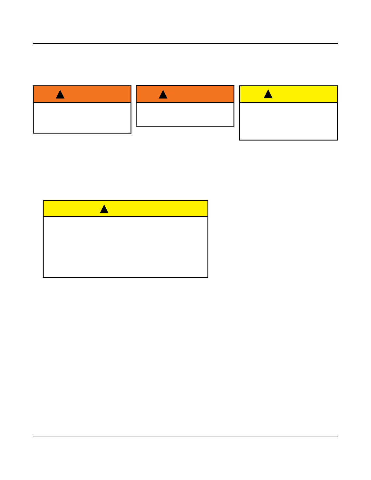
Safety Precautions . . . . . . . . . . . . . . . . . . . . . . . . . . . . . . . . . . . . 3
Required Tools. . . . . . . . . . . . . . . . . . . . . . . . . . . . . . . . . . . . . . . . 3
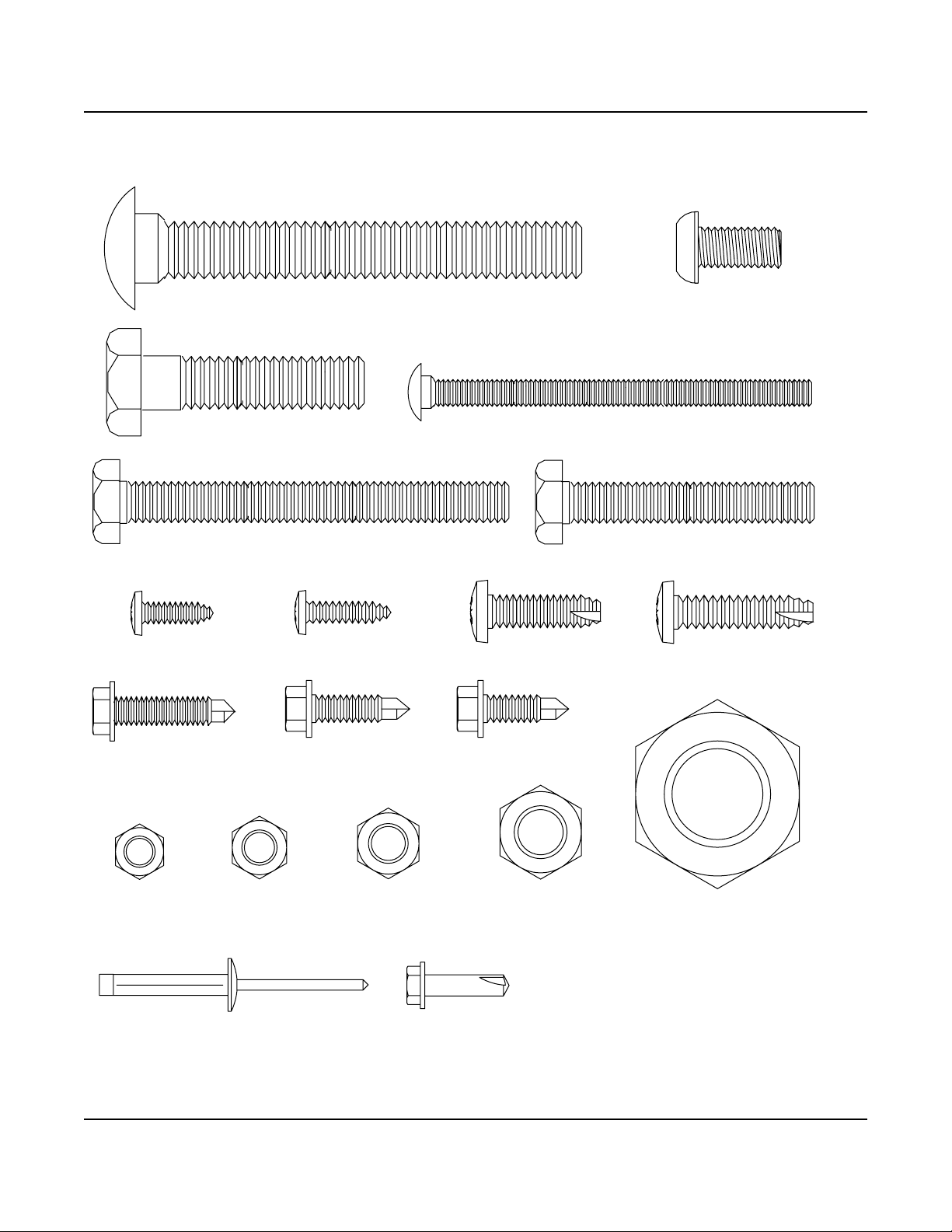
Fasteners. . . . . . . . . . . . . . . . . . . . . . . . . . . . . . . . . . . . . . . . . . . . 4
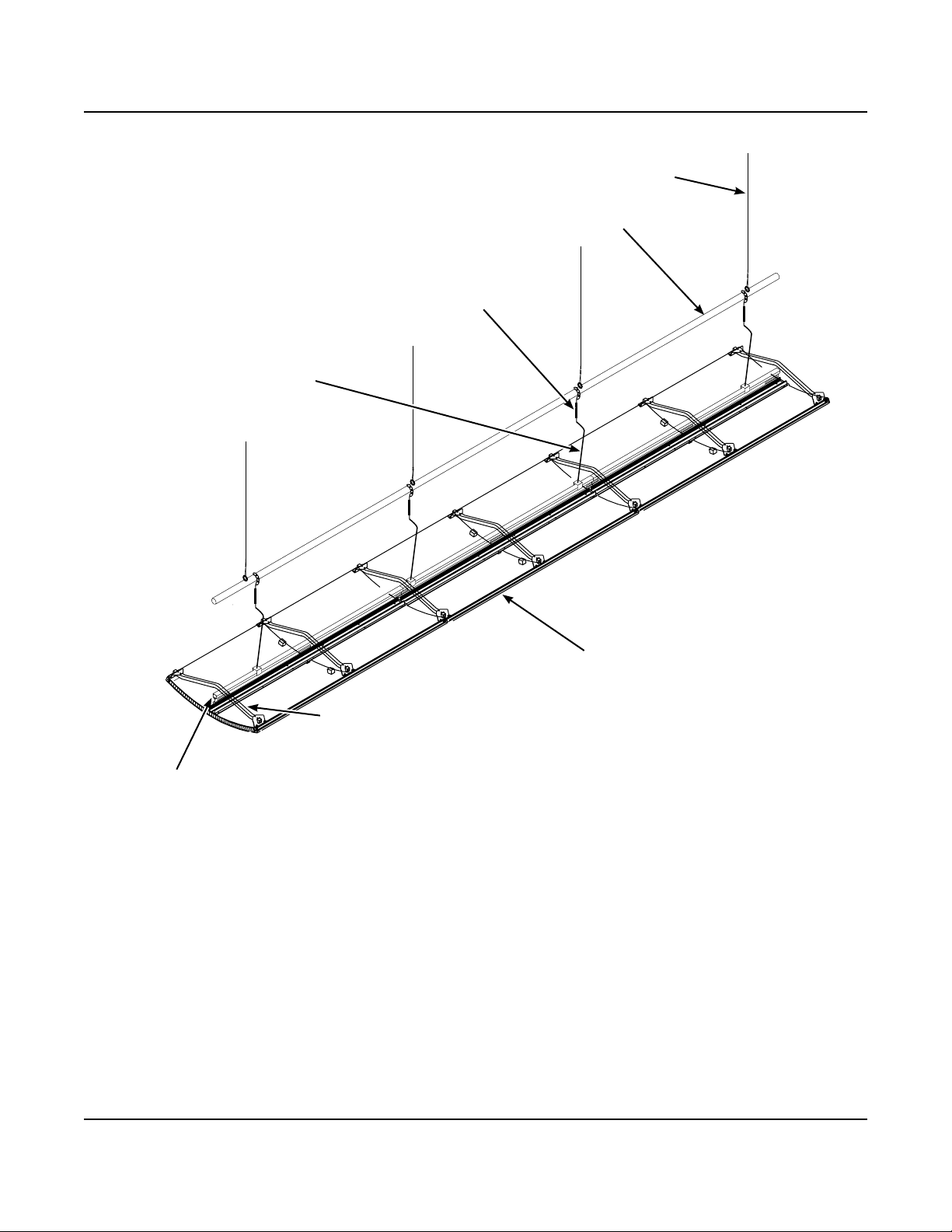
Ceiling Assembly Description . . . . . . . . . . . . . . . . . . . . . . . . . . . . 5
Before Installation . . . . . . . . . . . . . . . . . . . . . . . . . . . . . . . . . . . . . 6
Ceiling Installation . . . . . . . . . . . . . . . . . . . . . . . . . . . . . . . . . . . . . 7
Assemble the Truss................................7
Mark the Stage Area ...............................8
Attach the Hanger Arms to the Batten .................9
Attach the Hanger Arms to the Truss Assembly ..........12
Assemble a Ceiling Row Panel.......................14
Attach the Truss Assembly to the Ceiling Panel Row......16
Assemble the Bowstring to the Truss ..................18
Apply Tension to the Bowstring.......................20
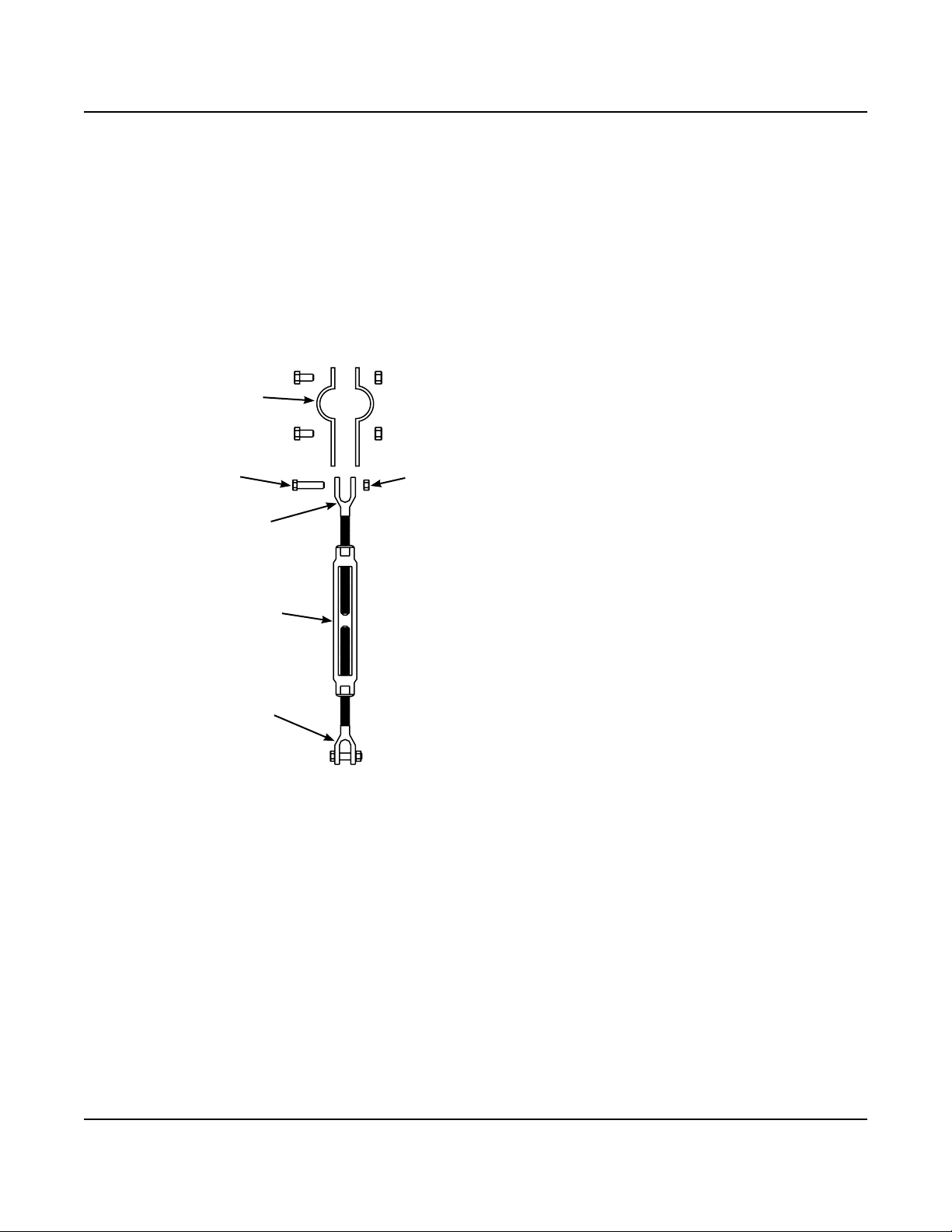
Install the Ceiling Stays.............................21
Fly the Ceiling Assembly............................23
Level the Ceiling Assembly ..........................24
Set the Ceiling Stay Performance Angle................25
Install the Ceiling Catch ............................27
Light Fixture Installation . . . . . . . . . . . . . . . . . . . . . . . . . . . . . . . . 28
Inspection .......................................28
Lieto LED Light Fixture Installation ....................28
Lieto LED Light Fixture Electrical Connection. . . . . . . . . . . . 29
LightFixtureConguration . . . . . . . . . . . . . . . . . . . . . . . . . . . . . . 30
InitialConguration ................................30
ConguretheDMXcatConnection ....................31
Lieto LED Light Fixture Communication ................31
DMXAddressInformation ...........................32
LED Power Settings Chart ..........................32
Troubleshooting...................................32
Light Fixture Operation . . . . . . . . . . . . . . . . . . . . . . . . . . . . . . . . . 32
Adjustment and Aiming .............................32
Photometrics .....................................33
Schematics . . . . . . . . . . . . . . . . . . . . . . . . . . . . . . . . . . . . . . . . . . 36
Lieto LED Light Fixture Electrical Schematic
(Diva Acoustical Ceiling) ........................36
Decals, Numbers and Logos. . . . . . . . . . . . . . . . . . . . . . . . . . . . . 36
Final Inspection . . . . . . . . . . . . . . . . . . . . . . . . . . . . . . . . . . . . . . . 36
Installation Instructions
Diva
®
Acoustical Ceiling
©Wenger Corporation 2020 Printed in USA 2020-05 Part #185C756-05
Wenger Corporation, 555 Park Drive, P.O. Box 448, Owatonna, Minnesota 55060-0448
Questions? Call.....USA: (800) 4WENGER (493-6437) • Worldwide: +1-507-455-4100 • wengercorp.com
Contents
Note: Please read and understand these instructions before using or setting up.
Note: Review all of the Installation Drawings and Reference Drawings.
Note: It is recommended that three or more people work together during the assembly.
Note: If you need additional information, contact Wenger Corporation using the information below.
Visit the Diva Acoustical Shell web page at wengercorp.com for more information.

2
Important User Information
General
Copyright © 2020 by Wenger Corporation
All rights reserved. No part of the contents of this manual may be reproduced, copied, or transmitted in any form
or by any means including graphic, electronic, or mechanical methods or photocopying, recording, or information
storage and retrieval systems without the written permission of the publisher, unless it is for the purchaser's
personal use.
Printed and bound in the United States of America.
The information in this manual is subject to change without notice and does not represent a commitment on the
part of Wenger Corporation. Wenger Corporation does not assume any responsibility for any errors that may
appear in these instructions.
In no event will Wenger Corporation be liable for technical or editorial omissions made herein, nor for direct,
indirect, special, incidental, or consequential damages resulting from the use or defect of these instructions.
The manufacturer reserves the right to change this product at any time.
The information in this document is not intended to cover all possible conditions and situations that might occur.
The end user must exercise caution and common sense when assembling or installing Wenger Corporation
products. If any questions or problems arise, call the Wenger Corporation at (800) 4WENGER (493-6437)
or +1-507-455-4100 worldwide.
Manufacturer
The Diva®Acoustical Ceiling is manufactured by:
Wenger Corporation
555 Park Drive
Owatonna, MN 55060
(800) 4WENGER (493-6437) • +1 (507) 455-4100
wengercorp.com
Intended Use
• The ceiling is intended for indoor use only and is not intended for outdoor use.
• Never expose the ceiling components to wind, humidity, or wet conditions.
• This product is intended to be assembled only as described in these instructions.
Installation
• The ceiling installation and use must comply with local regulations and codes.
• All personnel (including all temporary workers) installing or maintaining the ceiling must read and
understand these and other related installation instructions.
Warranty
Thisproductisguaranteedfreeofdefectsinmaterialsandworkmanshipforvefullyearsfromdate
of shipment. A full warranty statement is available upon request.

3
Make sure that anyone working
with the Diva Acoustical Ceiling
has read and understands these
instructions.
Always observe and comply
with the Warnings and
Cautions posted on the system
equipment.
Failure to comply with Warnings
and Cautions in this document
can result in damage to property
or serious injury.
Safety Precautions
Throughoutthisdocumentyoumayndcautionsandwarningswhicharedenedasfollows:
• WARNING: Failure to follow the instruction could result in serious injury or damage to property.
• CAUTION: Failure to follow the instruction could result in minor injury or damage to property.
Read all of these safety instructions before using the equipment.
* Save the wood blocks from the tower frame and ceiling truss packaging.
They will later be used during the tower assembly.
The following tools are required for assembly.
• Assorted wrenches
• Cordless drill and cordless impact driver
• 3/8", 1/2" and 9/16" hex nut bit
• Rubber mallet
• 24" (610 mm) carpenters' square
• 9/32" and 25/64" drill bit
• Chalk line
• Box level
• Phillips screwdriver
• Hex wrench set
• 3/8", 1/2" and 3/4" drive sockets
• 7/16" deep well socket and drive adapter
• Ratchet
• Anglender
• 100" (2.5 meter) measuring tapes (2)
• 25' (8 meter) tape rule
• Claw hammer
• Caulk gun
• Rivet gun
Required Tools
!WARNING !WARNING !WARNING

4
Fasteners
The fasteners shown below are contained in various Diva hardware kits.
Any fasteners remaining when an the installation is complete can be discarded.
Button Head Screw,
3/8-16 x 1"
Carriage Bolt, 1/4-20 x 3-1/2"
Screw, Self-drill,
1/4-14 x 3/4"
Hex Head Screw, 3/8-16 x 3-1/2"
Lock Nut,
1/4-20
Lock Nut,
1/2-13
Lock Nut,
3/8-16
Hex nut,
5/16-18
Tapping Screw,
5/6 x 1"
Carriage Bolt, 1/2-13 x 4"
Screw, Pan Head,
10-24 x 5/8"
Screw, Self-drill,
1/4-20 x 1-1/4"
Hex Jam Nut,
1-8
Hex Head Screw,
3/8-16 x 2-1/4"
Tapping Screw,
1/4-20 x 1/2"
Screw, Sheet Metal,
10-18 x 3/4"
Hex Head Screw, 1/2-13 x 2"
Screw, Self-drill,
1/4-20 x 1"
Rivet, Blind, Tri-Fold,
0.19 Dia Screw, Self-drill,
#10-16 x 0.75"

5
Ceiling Assembly Description
Lift Line
Stage rigging lift line.
Batten
Stage rigging pipe batten.
Turnbuckle Assembly
Used to level the ceiling assembly.
Hanger Arm Assembly
Connects the ceiling assembly
to the stage rigging.
Truss Assembly
Structural component
that also serves as an
electrical raceway.
Ceiling Panel
Providesthesoundreective
surface for the ceiling assembly.
Bowstring
Structural component used to
suspend the ceiling panel when
in the performance position.

6
To avoid damage to surfaces:
• Always wear gloves during assembly and installation.
• Lay any nished surfaces onto the cardboard and
foam packaging to help protect from damage.
• During assembly, dropped hardware can roll under
other components and cause damage to nished
surfaces.
Before Installation
Note: The weight of each ceiling assembly is calculated and does not include the weight of the rigging
or rigging hardware.
Note: UnlessspecicallyagreedbyWengerCorporation,allriggingandrigginghardwareisfurnished
by the general contractor or facility owner.
Make sure that all rigging and
rigging hardware is capable of
lifting the calculated weight of
the ceiling assemblies.
Components can be heavy or
dicult to handle and may
require three or more people
working together to lift or
assemble.
Personnel must always wear a
safety harness when working
above the oor surface.
1. Read and understand the entire ceiling installation section before starting the installation.
2. Make sure that all personnel installing (including any temporary workers)
are trained and understand the installation procedure.
3. Review all installation drawings and reference drawings.
Save these drawings for future reference.
4. Make sure that all items on the shipment packing list are present.
!CAUTION
!WARNING
!CAUTION
!WARNING

7
Assemble the Truss
1. Assemblethersttrussassemblyunderthebattenorcablesasfollows.
a. Attach a truss splice into the lower channel of the truss using one 1/4-14 x 3/4" self-drilling
screwontheupstageside.Tightenonlyngertightuntilallscrewsareinstalled.
b. Attach a truss splice bar into the upper channel of the truss using
two1/4-14x3/4"self-drillingscrews.Tightenonlyngertightuntilallscrewsareinstalled.
c. When all screws are installed and the trusses are aligned, tighten all screws.
d. Make sure that the truss caps are installed.
2. Find and mark the center location of the truss assembly.
Ceiling Installation
Always refer to the installation drawings for the location and arrangement of
ceiling panels.
STOP
Truss Splice Bar
Self-drilling Screw,
1/4-14 x 3/4"
Truss
Splice
Truss Cap
Truss
Truss Assembly
Truss Cap
First
Truss
Truss
Splice Bar
Truss Splice
Additional
Truss
Self-drilling Screw,
1/4-14 x 3/4"
Find and mark the
center location on the
Truss Assembly.
Upstage

8
Ceiling Installation (continued)
Mark the Stage Area
1. Mark the centerline of the stage as follows. Refer to the illustration below.
a. Make sure that the line sets are in the correct position.
b. Mark the mid point downstage between the two sides of the proscenium.
c Measure an equal distance from the two sides of the proscenium and mark the mid point upstage as
shown in the illustration below.
d. Snap a chalk line between the mid points marked upstage and downstage.
Downstage
Upstage
Stage Left Stage Right
Measure an Equal Distance
Strike a Chalk Line on the
Stage Centerline marked
from the intersection of
the two measurements.
Proscenium Opening
Measure an Equal
Distance
Measure an Equal
Distance
Batten
Mark the Stage Centerline position
on the Batten using the Plumb Line.
Batten at the Lowest Position
above the Stage Floor
Lift Lines
Chalked Stage
Centerline
Typical Stage
2. Place the battens or lift lines at the lowest position and mark the stage centerline position on the batten.

9
Attach the Hanger Arms to the Batten
Note: Always refer to the installation drawings for the location and arrangement of components.
1. Lower the batten to a working height.
2. Attach hanger assemblies to the batten at the locations indicated on the installation drawings as follows.
a. Remove a turnbuckle assembly with attached pipe clamp from the hanger kit hardware bag.
b. Remove the lock nut/hex head screw or the cotter key/cross pin that attach the pipe clamp
to the turnbuckle upper jaw.
Save this hardware for reattachment.
c. Adjust the turnbuckle to a position midway between the upper jaw and the lower jaw.
Ceiling Installation (continued)
Pipe Clamp
Turnbuckle Assembly
Lock Nut
or
Cross Pin
Hex Head Screw
or
Cotter Key
Upper Jaw
Lower Jaw

10
Ceiling Installation (continued)
e. Reattach the turnbuckle upper jaw to the pipe clamp using the hardware set aside in step 2b.
If using a cotter key, bend the ends in opposite directions around pin to secure cotter key.
f. Attach other turnbuckle assemblies to the batten by repeating steps 2a to 2e.
Batten
Batten
Pipe
Clamp
Turnbuckle
Assembly
Turnbuckle
Assembly
Lift Lines
Batten
Lift Line
Batten
Pipe Clamp
Pipe
Clamp
Pipe
Clamp
Attach the Hanger Arms to the Batten (continued)
2. continued...
d. At the proper locations, attach the pipe clamp to the batten using two hex head screws and tighten
securely.

11
Ceiling Installation (continued)
Attach the Hanger Arms to the Batten (continued)
3. Attach a hanger arm to each turnbuckle assembly as follows.
a. Remove the lock nut and hex head screw form a turnbuckle lower jaw.
Set aside the lock nut and screw.
b. Insert the hanger arm upper eye into the turnbuckle lower jaw and re-attach the lock nut and
screw set aside in step 3a with a pair of 9/16" combination wrenches.
Refer to the illustration below. Align the hanger arms as shown on the installation drawings.
c. Attach other hanger arms to the turnbuckle assemblies by repeating steps 3a and 3b.
Batten
Lift Lines
Turnbuckle
Hanger
Arm
Hanger Arm
Upper Eye
Lock Nut
and Screw
Turnbuckle
Batten
Note: Align the hanger arms as shown
in the installation drawings.
Turnbuckle
Lower Jaw

12
Ceiling Installation (continued)
Attach the Hanger Arms to the Truss Assembly
1. Attach the hanger assemblies to the ceiling truss.
a. Remove a hanger assembly from the hanger kit hardware bag.
b. Unscrew the two lock nuts and remove the carriage bolt and the hex head screw.
Save the hanger straps, lock nuts, carriage bolt, and screw.
Be sure that the hanger assemblies
cannot slip o of the ceiling truss.
Hanger Assembly Strap
Carriage Bolt
Hex Head Screw
Lock Nut
Hanger Assembly
Truss
Hanger
Assembly
Carriage
Bolt Lock Nut
Truss
Assembly
Hanger
Arm
Batten
Lift Line
Hanger
Assembly
Head of Carriage Bolt
must be on downstage
side of truss.
c. Withtheceilingtrusscenteredbelowthebatten,attachahangerassemblytothetrussbyttingthe
two hanger assembly straps onto the truss as shown below.
Attachthecarriageboltandalocknutsetasideinstep1bngertight.
d. Slide the hanger assembly on the truss so that it aligns to a hanger arm.
Tighten the lock nut with a 3/4" combination wrench.
e. Assemble additional hanger assemblies below each hanger arm by repeating steps 1a to 1d.
!CAUTION

13
Ceiling Installation (continued)
Attach the Hanger Arms to the Truss Assembly (continued)
2. Connect the hanger arms to the ceiling row truss assembly.
a. Lowerthebattenandhangerarmsuntiltheeachhangerarmlowereyewilltintoeach
hanger assembly as shown in the illustration below.
b. Attach a hanger arm lower eye to a hanger assembly with the hex head screw and lock nut set
aside in step 1b on the previous page. Tighten with a pair of 3/4" combination wrenches.
c. Attach the other hanger arms to the ceiling panel row by repeating steps 2a and 2b.
d. Adjust the turnbuckles so that there is equal tension on each hanger arm.
e. Using a pair of 3/4" combination wrenches, tighten all of the lock nuts and screws.
3. Raise the batten to allow for room to work.
Truss
Hanger
Assembly
Hanger Arm
Lower Eye
Hex Head Screw
and Lock Nut
Truss
Assembly

14
Ceiling Installation (continued)
Assemble a Ceiling Row Panel
Assemble a ceiling panel row as follows.
Note: Always refer to the installation drawings for the location and arrangement of ceiling panels.
1. To prevent damage, lay the ceiling panels on 4' x 8' sheets of packing material.
Make sure that the ceiling panels are arranged below the batten with about a 4" (102 mm) of space
between each panel as shown below.
Ceiling Panel
4' x 8' Sheets of
Packing Material
Approximately 4" of spacing
Batten
Lift Line
Foam
Strip
Ceiling Panel
Recess
Ceiling
Panel
Ceiling Panel
Insert a Foam Strip into one Recess between
two Ceiling Panels being joined together.
Downstage
Edge
Orient panels so
part number labels
are on Stage Right.
2. Where two ceiling panels join together, insert a foam strip into the recess of one of the two ceiling panels
as shown below.
a. Trim the foam strip length if necessary.
b. Make sure that the foam strip is fully seated into the recess.

15
Ceiling Installation (continued)
Assemble a Ceiling Panel Row (continued)
3. Connect two adjacent ceiling panels together.
Refer to the illustrations below.
a. Insert a 1/4-20 x 3-1/2" carriage bolt through the square hole in a panel inner corner clip,
through the two outer corner clips, and through the other panel inner corner clip.
b. Attach a 1/4-20 hex nut to the carriage bolt so that it is snug.
c. Attach a 1/4-20 x 3-1/2" carriage bolt and 1/4-20 hex nut on the opposite side of the panels
by repeating steps 3a and 3b.
d. With two people working together, use 7/16" sockets with universals and tighten the hex nuts
(keep the tension equal on both sides by tightening each side at the same time)
until the two panel inner corner clips begin to bend.
Carriage Bolt,
1/4-20 x 3-1/2"
Hex Nut, 1/4-20
Panel Outer
Corner Clip
Panel Inner
Corner Clip
Ceiling Panel
Panel Inner
Corner Clip
Ceiling Panel
Ceiling Panel
Recess
Ceiling Panel
4. Connect the other ceiling panels by repeating step 2 and step 3.

16
Ceiling Installation (continued)
Attach the Truss Assembly to the Ceiling Panel Row
Refer to the illustration below and follow the installation drawings for proper location.
1. Place the truss assembly onto the ceiling panel center channel.
a. Make sure that the truss assembly is centered over the ceiling panel center channel.
Ceiling Panel Row
Truss
Assembly
Note: Align the truss assembly
to the ceiling panel row.
Ceiling Panel Joint
Note: Install a hanger bracket
above each seam at
these points.
Hanger Bracket
Assembly
Truss
Assembly
Truss Hanger
Bracket Slot
Hanger
Bracket Leg
Hanger Bracket Assembly
Jack Tube
Bearing
Bearing
Upstage
Side
Note: Hanger bracket assemblies are preassembled
and a jack tube may not be required.
Follow the installation drawings.
b. Insert a hanger bracket assembly into each truss hanger bracket slot that aligns with a
ceiling panel joint or end edge.
c. Slide one bracket into each side of the hanger bracket leg until they touch each other.

17
Ceiling Installation (continued)
Attach the Truss Assembly to the Ceiling Panel Row (continued)
2. Use a rubber mallet to seat each hanger bracket onto the ceiling panel center channel.
Note: Each hanger bracket assembly faces the upstage side and must be centered on the seam between
two adjacent ceiling panels.
Truss Assembly
Hanger Bracket Leg
Ceiling Panel
Center Channel
Note: The hanger bracket must be
pressed downward until it is
ushwiththetopoftheceiling
panel center channel legs.
Truss
Assembly
Hanger Bracket
Assembly
Self-drilling Screws,
1/4-14 x 3/4"
Self-drilling Screws,
1/4-14 x 3/4"
Upstage
Upstage
3. Attach the hanger bracket assemblies to the truss assembly.
a. Use a cordless drill and a 9/16" hex nut bit.
b. Screw two 1/4-14 x 3/4" self-drilling screws, through each side of the hanger bracket legs and
ceiling panel center channel as shown below.

18
Ceiling Installation (continued)
Assemble the Bowstring to the Truss
1. Attach a bowstring assembly to a ceiling panel as follows. Begin at one end of the ceiling panel row.
a. Using a 3/8-16 x 2-1/4" hex head screw, and a 3/8-16 lock nut, attach the bowstring jack
to the bowstring as shown in the illustration below.
b. Slideaceilingclipontoeachendofthebowstring.Theceilingclipangesmustfacetothe
inside or each other.
Short
Bowstring
Ceiling
Clip
Short
Bowstring
Ceiling Clip
Short
Bowstring
Hex Head Screw,
3/8-16 x 2-1/4"
Lock Nut,
3/8-16
Bowstring
Jack
Ceiling Clip
Flange
Hex Jam Nut,
1-8
Bowstring Jack
Hanger Bracket
Jack Tube
c. Place the bowstring jack into the hanger bracket jack tube as shown below.

19
Ceiling Installation (continued)
Assemble the Bowstring to the Truss (continued)
2. Positiontheceilingclipsushwiththeouteredgeoftheceilingpanel.Makesureneither
ceiling clip extends beyond the ceiling panel edge. Refer to the illustration below.
3 Usingacordlessdrillandthe9/32"drillbit,drillholesintotherearangeofthepanelextrusionusingthe
ceiling clip mounting holes as a template for the drill bit.
Do not drill through the to face of the panel.
4. Usinga1/2"openendwrench,screwtwotappingscrewsintothe9/32"holesintherearange
of the ceiling panel extrusion drilled in step 3. Do not over tighten the screw!
Note: If the tapping screw is over tightened and strips the thread, fasten a 9/32" nut to the screw.
5. Using a cordless drill and a 3/8" hex drive bit, screw two self-drill screws through the two
ceiling clip bowstring mounting holes in each ceiling clip into the bowstring.
Do not over tighten the screw!
Ceiling Panel
Extrusion Rear Flange
Short Bowstring
Ceiling Clip
Ceiling Panel
Self-drill Screw,
1/4-14 x 3/4"
Ceiling Clip
Bowstring Mounting
Hole
Ceiling Panel
Seam
Short
Bowstring
Tapping Screw,
5/16-18 x 1-1/4"
Upstage
6. Attach the additional bowstrings to the ceiling row by repeating steps 1a to 5.
Make sure that the bowstrings are centered on the panel seams.

20
Ceiling Installation (continued)
Apply Tension to the Bowstring
1. Lift a bowstring upward by hand to remove any slack.
2. While lifting the bowstring, turn the hex jam nut, 1-8, clockwise as shown below until the jam nut is
snug against the jack tube.
3. Use a 1-1/2" open end wrench and turn the jam nut an addition full turn clockwise (six ats).
4. Repeat steps 1 through 3 above on all of the other bowstrings.
Bowstring
Hex Jam Nut, 1-8
Jack Tube
Note: Turn the jam nut clockwise until it is snug against the jack tube.
Then, turn the jam nut an additional full turn clockwise (six ats).
Do not load weights onto the
Arbor until tension is applied
to all of the Bowstrings.
!WARNING
Other manuals for Diva
4
This manual suits for next models
1
Table of contents
Other Wenger Speakers System manuals