Wensar MAB 201 User manual

1
ANALYTICAL BALANCE
MAB 201 - 220g / 0.1mg
MAB 301 - 320g / 0.1mg

2
Contents
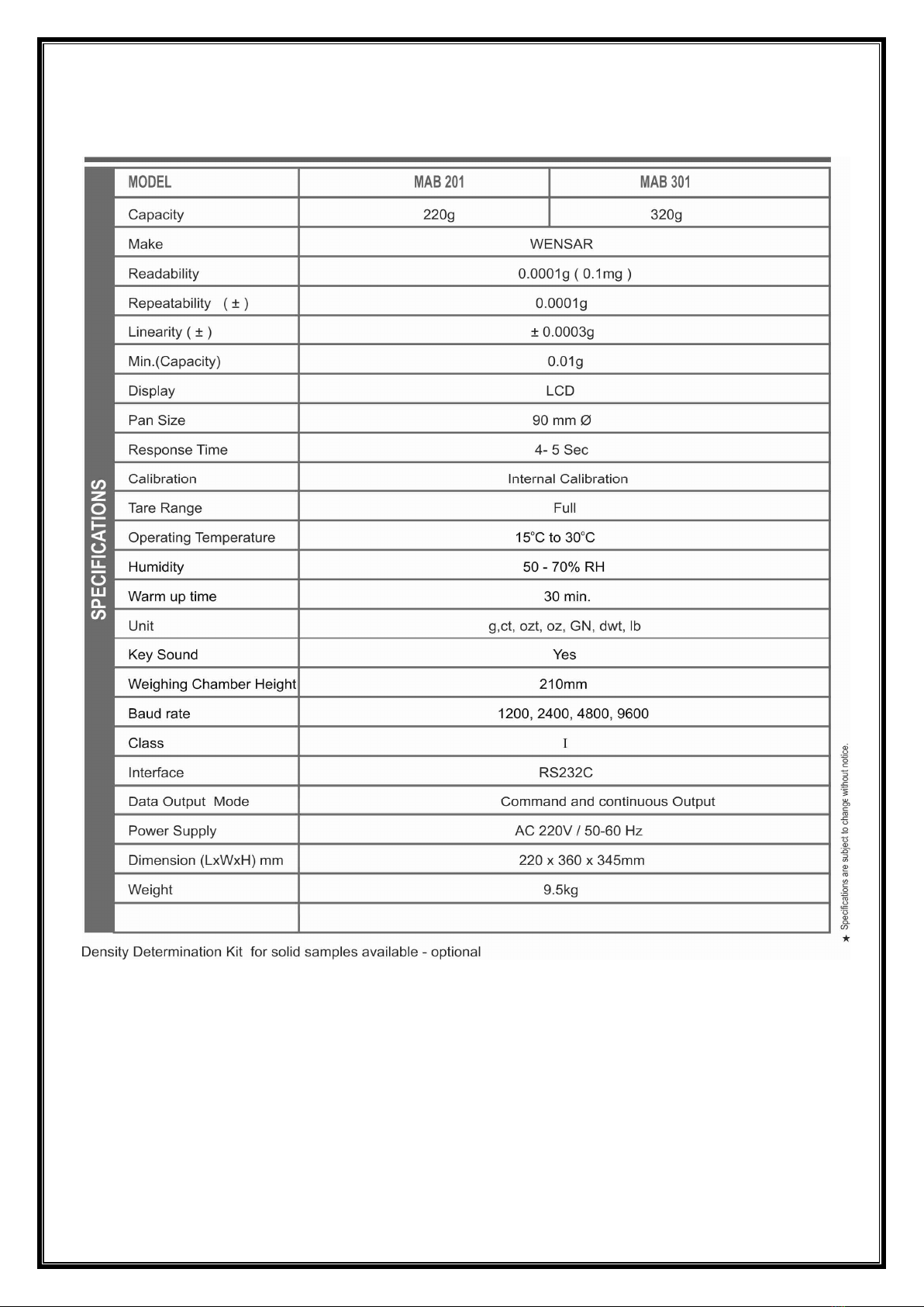
1 Technical data ................................................................................................................................... 4
2 Introduction ...................................................................................................................................... 4
2.1 Proper Use ................................................................................................................................. 5
2.2 Improper Use............................................................................................................................. 5
2.3 Control of inspection, measuring and test equipment .............................................................
3 Precautions .......................................................................................................................................
4 Transportation and Storage..............................................................................................................
4.1 Acceptance check ......................................................................................................................
4.2 Packing ......................................................................................................................................
5 Unpacking, Setup and Commissioning ............................................................................................. 7
5.1 Installation Site, Location of Use ............................................................................................... 7
5.2 Unpacking / Installation ............................................................................................................ 7
5.3 Mains connection ...................................................................................................................... 8
5.4 Connection of peripheral devices ............................................................................................. 8
5.5 Initial Commissioning ................................................................................................................ 8
5. Adjustment ................................................................................................................................ 8
5.7 Calibration ................................................................................................................................. 8
5.7.1 Internal calibration: ........................................................................................................... 8
5.7.2 Internal calibration: ........................................................................................................... 8
Basic Operation................................................................................................................................. 9
.1 [Power On/OFF] ........................................................................................................................ 9
.2 TARE ........................................................................................................................................ 10
.3 CAL - [calibration with external weight] ................................................................................. 10
.4 UNIT- [multifunctional key] ..................................................................................................... 10
.4.1 Weighing unit selection [weighing mode] ....................................................................... 10
.5 Print function [print mode] ..................................................................................................... 10
. Pieces counting function [counting mode] ............................................................................. 10
.7 Underfloor weighing ............................................................................................................... 11
7 Density determination (Hydrostatic weighing) .............................................................................. 11
7.1 Density determination of solids .............................................................................................. 12
7.2 Determining density of liquids ................................................................................................ 12
7.3 Influencing magnitudes and error sources ............................................................................. 12
8 Display Information / Error messages ............................................................................................ 12

3
9 Interface RS 232C............................................................................................................................ 13
9.1 Technical Data ......................................................................................................................... 13
9.2 Description of the data transfer .............................................................................................. 13
9.3 Remote control instructions ................................................................................................... 13
9.4 RS232 Pinout (9-pin D-Sub) ..................................................................................................... 14
10 Configuration &Explain of the function setting .............................................................................. 14
11 Maintenance and Servicing ............................................................................................................ 1
11.1 Cleaning ................................................................................................................................... 1
11.2 Maintenance and repair .......................................................................................................... 1
12 Trouble Shooting ............................................................................................................................ 1

4
1 Technical data
2 Introduction
The laboratory analytical balance MAB 201 is designed to meet the needs of laboratories,
industry and commercial users and it offers very wide range of functions: weighing, parts
counting or density determination. Its a built-in standard weight and a precision automatic
loading device, our computer controlled mechanism with precise motors complete the loading
and unloading operation of the test weight. The result is an easy, fast and automatically working
mechanism to always get the best results.

5
Balance is equipped with precision temperature measurement circuit, the perception of
temperature changes to 0.01 degrees. If the environment temperature change more than 1.5
degrees, the balance will automatically start the calibration function, to keep the balance of the
degree of accuracy of measurement. In addition, if the last calibration is 3 hours ago, the balance
will start an automatic calibration to always keep good results.
Electromagnetic force compensation technology.
• High precision, sensitivity and rapid response time.
• High quality materials and an optimized power supply.
• High reliability and long service life.
• A robust base made of powder coated aluminum cast.
• An easy-cleaning, durable and stable metal shell with glass wind protection.
• A removable stainless steel pan can be cleaned easily.
• A Level Indicator, four adjustable feet.
• External calibration, zeroing searches, parts counting function, tare function, density
determination
• 7 Weighing units (g, ct, ozt, oz, GN, dwt, lb).
• Large LCD display with backlight, digit height 15 mm.
• An integrated RS-232-interface enables you to automatically send the weighing data to PC
• Powered by the external 3 pin power cord.
2.1 Proper Use
The balance you purchased is intended to determine the weighing value of material to be
weighed. It is intended to be used as a “non-automatic” balance, i.e. the material to be weighed
is manually and carefully placed in the center of the weighing plate. As soon as a stable weighing
value is reached the weighing value can be read.
2.2 Improper Use
• Do not use the balance for dynamic weighing. In the event that small quantities are removed or
added to the material to be weighed, incorrect weighing results can be displayed due to the
“stability compensation” in the balance. (Example: Slowly draining fluids from a container on
the balance.)
• Do not leave permanent load on the weighing plate. This may damage the measuring system.
• Impacts and overloading exceeding the stated maximum load (max) of the balance, minus a
possibly existing tare load, must be strictly avoided. Balance may be damage by this.
• Never operate the balance in explosive environment. The balance is not explosion protected.
• The structure of the balance may not be modified. This may lead to incorrect weighing results,
safety-related faults and destruction of the balance.

2.3 Control of inspection, measuring and test equipment
As part of quality assurance the measuring-related properties of the balance and the available
adjusting weight must be checked regularly. The responsible user must define a suitable interval
as well as the nature and scope of this test.
3 Precautions
• Environmental conditions: only use indoor, check the detailed environment conditions for
temperature and humidity in the technical details above.
• Do not use the scale in any high temperature fluctuations and avoid strong airflows, vibrations
and dust. The balance could never get wet and make sure that the balance is not used in an
environment with extreme temperature and humidity.
• Do not use the balance in explosive conditions.
• Only use the extender cable, which with ground wire.
• If the power line cable is damaged, the appliance must be unplugged immediately and the
power line cable be replaced.
• Place the balance on a stable surface and set it horizontally with the help of the adjustable feet
and the spirit level.
• The electronic balance is a precision measuring instrument and must be handled with great care.
Violation of limit of weighing range or impact can cause permanent damage to the balance.
• The balance needs a warm up time for about 1 hour before using.
• Please do not use aggressive cleaning agents (solvents or similar agents), but a cloth dampened
with mild soap suds. Ensure that no liquid penetrates into the device and wipe with a dry soft
cloth.
• Do not overload the balance more than 20% of maximum load (Max). Do not press the pan with
a hand!
• By maintenance please notice the information in Chapter “Maintenance and Servicing”.
• If the balance seems not to operate properly, unplug it from the mains and do not use until
checked by authorized service.
• All repairs and necessary regulations can be made by authorized personnel only.
4 Transportation and Storage
4.1 cceptance check
When receiving the appliance, please check packaging immediately, and the appliance itself
when unpacking for possible visible damage.
4.2 Packing
• Keep all parts of the original packaging for a possibly required return
• Only use original packaging for returning.
• Prior to dispatch disconnect all cables and remove loose/mobile parts.
• Reattach possibly supplied transport securing devices.

7
• Secure all parts such as the glass wind screen, the weighing platform, power
unit etc. against shifting and damage.
5 Unpacking, Setup and Commissioning
5.1 Installation Site, Location of Use
The balances are designed in a way that reliable weighing results are achieved in common
conditions of use. You will work accurately and fast, if you select the right location for your
balance.
Therefore, observe the following for the installation site:
Major weighing deviations (incorrect weighing results) may be experienced should electro-
magnetic fields (e.g. due to mobile phones or radio equipment), static electricity accumulations
or instable power supply occur. Change location or remove source of interference.
• Place the balance on a firm, level surface;
• Avoid extreme heat as well as temperature fluctuation caused by installing next to a radiator or
in the direct sunlight;
• Protect the balance against direct draughts due to open windows and doors;
• Avoid jarring during weighing;
• Protect the balance against high humidity, vapors and dust;
• Do not expose the device to extreme dampness for longer periods of time.
• Non-permitted condensation (condensation of air humidity on the appliance) may occur if a cold
appliance is taken to a considerably warmer environment. In this case, acclimatize the
disconnected appliance for ca. 4 hours at room temperature.
• Avoid static charge of goods to be weighed or weighing container.
5.2 Unpacking / Installation
Carefully remove the balance from the packaging, remove plastic cover and setup balance at the
intended workstation.
1. Take the balance and supplied accessories (a feeder, pan elements) out of the box.
2. Place the balance on a stable ground not affected by mechanical vibrations and airflows.
3. Level the balance with foot screws so that the air bubble in water-level is in the middle.
4. Plug the Powercord to the power socket at the back of the balance.
5. Connect the power cord to an AC220V ± 10% 50Hz ± 1Hz outlet.
Packing
• Balance
• Glass Wind protection
• Weighing pan
• AC adapter
• Operating Instructions

8
5.3 Mains connection
Before connecting the mains power cord check if the printed voltage value is the same as the
local supply voltage.
Only use the original supplied mains power cord. Otherwise there is a risk that the Scale be
impaired.
5.4 Connection of peripheral devices
The balance may send data to a computer or a printer through RS232C port.
When cooperating with the balance, a computer should be equipped with a program which
enables processing data from the balance.
Before connecting or disconnecting of additional devices (printer, PC) to the data interface,
always disconnect the balance from the power supply.
5.5 Initial Commissioning
In order to obtain exact results with the electronic balances, your balance must have reached
the operating temperature (warming up time 1 hour). During this warming up time the balance
must be connected to the power supply
The accuracy of the balance depends on the local acceleration of gravity.
Please read the information carefully in chap. “Adjustment”.
5.6 djustment
As the acceleration value due to gravity is not the same at every location on earth, each balance
must be coordinated - in compliance with the underlying physical weighing principle - to the
existing acceleration due to gravity at its place of location (only if the balance has not already
been adjusted to the location in the factory). This adjustment process must be carried out for
the first commissioning, after each change of location as well as in case of fluctuating
environment temperature. To receive accurate measuring values it is also recommended to
adjust the balance periodically in weighing operation.
5.7 Calibration
5.7.1 Internal calibration:
When the balance display is “0” then press the “CAL” key.
The balance turns into the automatic internal calibration status and displays “CAL”, now the
internal weight loading and unloading device for automatic calibration will start their work.
After 30 seconds the display “0”, that means the calibration is finished. In the normal use, the
internal calibration should be used to calibrate the balance.
When there was no calibration within the last 3 hours the scale will calibrate itself.
5.7.2 Internal calibration:
External Calibration:
First you should get ready the standard weight for external calibration in the required OIML-
Tolerance (E2 for example). When the balance display is “0” press and hold the “CAL” key until
the display changes from "CAL-INT" to "CAL-E".

9
When you now release the "CAL" key the scale will display "C XXX" (XXX is the weight of the
standard weight. Example: display "C 200" should be put on the standard weight of 200g), put
on the calibration weights, after the weight of the calibration weight displayed and the stable
weight symbol "g" shows that means the calibration is complete. If press the "CAL" key shows
"C----F", the zero point is unstable, and the "TARE" key can be re pressed to show the return to
zero. Now press the "CAL" key again.
Adjustment with recommended adjustment weight (default setting) Weight value of the
required adjustment weight seeschap. 1 “Technical data”. Weights of different nominal values
may be used for adjustment but are not optimal for technical measuring.
Operating elements
1. Weighing pan 2. Pan support ring 3. Wind protection 4. Underfloor weighing widget
5. Sealing cap . Adjustable feet 7. RS232 Interface 8. Level Indicator
9. Power socket 10. Power Cord 11. ON/OFF key 12.Calibration key
13.Unit change key 14.Counting key 15.Print key 1 .Tare key
6 Basic Operation
After new purchase of the balance or after a long storage, you have to calibrate the balance
before the first commissioning. Level the balance with the adjustable feet horizontal until the air
bubble in the level is in the center of the Level Indicator. Give the balance after changing the
location a warm-up time min. 1 hour before using. This time is necessary for the balance to
adapt to the eventual temperature.
6.1 [Power On/OFF]
Press the[On/OFF]button to turn on the balance. The display shows the message "ON". Then the
max. weighing range is displayed. The balance will carry out a self-test (F----1 to F----9). When
the "0.0000 g" in display appears, the balance is ready for operation.
Press the [On/OFF]button and keep it pressed, until the display shows the message “OFF”. The
balance will switch off then.

10
6.2 T RE
When the pan is empty and indication is different than zero press [TA E] key.
Weighing with tare: Place the weighing box and press the[TA E] button. After standstill control
the zero display appears. The weight of the container is now internally saved. Weigh the
material, the net weight will be indicated. The weight of the weighing container will be displayed
as a minus number after removing the weighing container. The tare weight is saved until it is
deleted. Remove the load from the balance and press the [TA E] button. The tare procedure can
be repeated as many times as necessary, for example with initial weighing of several
components for a mix (add-on weighing). The limit is reached when the total weighing range
capacity is full.
6.3 21C L - [calibration with external weight]
The balance has an external calibration function.
The adjustment procedures see chap. "External calibration”.
6.4 UNIT- [multifunctional key]
The [UNIT] - button is a multi-function button.
6.4.1 Weighing unit selection [weighing mode]
Under the weighing mode, use the UNIT key to choose weighing units: g (gram), ct (carat), ozt
(troy ounce), oz (ounce), GN (gran), dwt (pennyweight) and lb (pound).
1 g = 5 ct
= 0.032150747 ozt
= 0.035273962 oz
= 15.43235835 GN
= 0.643014931 dwt
= 0.0022046226 lb
6.5 Print function [print mode]
The balance can be connected via the RS232C interface directly to a printer or PC.
Press the “PRINT” key to send the weight to the output device.
6.6 Pieces counting function [counting mode]
Before the balance can count parts, it must know the average part weight (i.e. reference).
Proceed by putting on a certain number of the parts to be counted. The balance determines the
total weight and divides it by the number of parts, the so-called reference quantity (1, 10, 20, 50,
or 100). Counting is then carried out on the basis of the calculated average piece weight.
As a rule: The higher the reference quantity the higher the counting exactness.
Follow these steps:
a) Place as many pieces to add-up as required by the reference quantity. Press the “COUNT” key,
display “1” that means into the counting mode, Press the [UNIT] button to enter the setting

11
menu. The display now shows the number "1" and the unit "Pcs". Using the [UNIT] button select
the reference quantity (1, 10, 20, 50, or 100).
b) After successful reference determination the current quantity is displayed and the unit “Pcs”.
c) Remove reference weight. The balance is now in parts counting mode counting all units on the
weighing plate.
6.7 Underfloor weighing
Objects unsuitable for placing on the weighing scale due to size or shape may be weighed with
the help of the underfloor weighing device.
Proceed as follows:
Switch off the balance
Open the Sealing cap at the balance bottom.
Suspend hook for underfloor weighing carefully and completely.
Place weighing balance over an opening.
Attach load to hook and carry out weighing procedure.
• Always ensure that all suspended objects are stable enough to hold the desired goods to be
weighed safely (danger of breaking).
• Never suspend loads that exceed the stated maximum load (max) (danger of breaking).
• Always ensure that there are no persons, animals or objects that might be damaged underneath
the load.
• After completing the underfloor weighing the opening on the bottom of the balance must
always be closed (dust protection).
7 Density determination (Hydrostatic weighing)
According to the Archimedes’ principle, any object, wholly or partially immersed in a fluid, is
buoyed up by a force equal to the weight of the fluid displaced by the object.In other words, an
immersed object is buoyed up by a force equal to the weight of the fluid it actually displaces.
For the density determination of solid material, the solid is weighed first in air and then in the
measuring liquid. Because of the density of the water is 1.0 g/cm ³, can determine the volume of
the displaced water and also the volume of object. From the weight difference results the
buoyancy calculates the density.
• The density is determined with help of the underfloor weighing device.
• Hydrostatic density determinations succeed only with the objects, which have
a higher density than water (1 g/cm
3
).
Example:
A piece of metal in the air weight 100 g and weighs 80 g in water. Therefore, the object has 20 g
(= 20 cm³) water displaced. Its volume is therefore 20 cm³. Now it is easy to determine the
density of the metal piece.

12
7.1 Density determination of solids
For the density determination of solid material, the solid is weighed first in air [ A ] and then in
the measuring liquid [ B ]. If the density of the buoyancy medium [ ρ
o
] is known, the density of
the solid [ ρ ] is calculated as follows:
=
−
= Density of the sample
= Weight of the sample in air
= Weight of the sample in the measuring liquid
= Density of the measuring liquid
7.2 Determining density of liquids
For density determination of liquids, a glass sinker is used, whose volume ([ V ] see embossing) is
known. The glass sinker is weighed first in air [ A ] and then in the liquid [ B ] whose density is to
be determined. According to the Archimedes’ principle, any object, wholly or partially immersed
in a fluid, is buoyed up by a force equal to the weight of the fluid displaced by the object.
The volume [ V ] of the glass sinker is same as the volume of the displaced liquid.
Buoyant force of the glass sinker = weight of the glass sinker in air [ A ] - weight of the glass
sinker in the measuring liquid [ B ]
That implies that:
= −
+
= Density of the sample liquid
= Weight of the glass sinker in air
= Weight of the glass sinker in the measuring liquid
= Volume of the glass sinker
= Density of air (0.0012 g/cm
3
)
7.3 Influencing magnitudes and error sources
Air Pressure
Temperature
Volume deviation of the sinking object (± 0.005cm
3
)
Surface tension of the liquid
Air bubbles
Immersion depth of the sinking object
Porosity of the object
8 Display Information / Error messages
F----1 Date over display scope
F----2 A/D-switch disorder
F----3 Function key disorder
F----5 Sensor signal disorder /Load Cell defect

13
F----L Lower zero position of sensor signal
F----H Weighing capacity is exceeded
C----F Calibration error, instability or not at zero point during calibrating
C----H Calibration error, items on the pan or at higher zero point during calibrating
E----- Storage calibration data error, re-calibration is necessary
------ Zero point of the scale disorder / mechanical defect of the scale
9 Interface RS 232C
An integrated RS-232-interface enables you to automatically send the weighing data to
PC.Relevant codes and control commands are specified as following.
9.1 Technical Data
• 8-bit ASCII Code
• 1 start bit, 8 data bits, 1 stop bits, noparity bit
• Bit rates supported include: 600, 1200, 2400, 4800 and9 00bit/s. (default setting is 00)
• Miniature plug is necessary (9 pin D-Sub)
9.2 Description of the data transfer
Symbols
-
/+
minus
-
sign / for positive numbers this is output as blank
Data
value of weight / decimal, depending on weighing value
Unit
Units
/
Pcs
.
STP
stop character
CR
Carriage
Return
Data format: 14-bits Output (ASCII Code):
-
/+
Data
Unit
STP
CR
2 bits
7 bits
3 bit
s
1 bit
1 bit
9.3 Remote control instructions
Via the RS232 data interface, the computer can control the balance with subsequent commands.
If the transmit / device setting is 27 (27=1B
hex
, default setting), the remote control commands
are sent to the balance by ASCII code:
1BH+70H(ACSIICode p): sending data (Print)
1BH+71H(ACSIICode q): calibration function is active (CAL - Key)
1BH+72H(ACSIICode r): Counting function is active
1BH+73H(ACSIICode s): Weighing unit selection
1BH+74H(ACSIICode t): Taring (TARE - Key)

9.4 RS232 Pinout (9-pin D-
Sub
DE-9 plug pin-out (9-pin
., male),
available at DTE
DTE - data terminal equi
pment (Terminals
DCE - data circuit-
terminating equipment (
Signal
Abbreviation
Name
RxD
Receive
Data
TxD
Transmit
Data
GND
Ground
Application Example:
If the setting is C3---2, C4---
27 (default setting), the codes shown in VB as following:
MSComm1.Settings = " 00,n,8,1"
MSComm1.Output = Chr(&H1B) + C
’or
MSComm1.Output = Chr(27) + Chr(112)
’or
MSComm1.Output =Chr(27) +"p"
Do DoEvents
Loop Until
MSComm1.InBufferCount = 14
a = MSComm1.Input
Print a
10 Configuration &E
xplain
T
he settings of the balance can be changed in the
adjusted to in
dividual weighing requirements.
way that normally no more changes must be made, only at special conditi
Overview:
In the off state press the [CAL
] button and keep it pressed, press the [
balance. Now the balance is accessed to the setting menu. Using the [
menu items (C1-C4) can b
e selected on
setting value. After all points have been configured,
automatically into
weighing mode.
14
Sub
)
., male),
as it is usually
available at DTE
DE-9 socket pin-out (9
-
usually available at DCE
pment (Terminals
resp. computer)
terminating equipment (
Balance)
Pin
Typical purpose
DE
-
9
DTE (e.g.
PC)
Carries data from
DCE to DTE. 2 Input
Carries data from
DTE to DCE. 3
Output
5
-
27 (default setting), the codes shown in VB as following:
MSComm1.Settings = " 00,n,8,1"
MSComm1.Output = Chr(&H1B) + C
hr(&H70)
’sent a pr nt commando
MSComm1.Output = Chr(27) + Chr(112)
MSComm1.Output =Chr(27) +"p"
MSComm1.InBufferCount = 14
xplain
of the function setting
he settings of the balance can be changed in the
setting
menu. This way, the balance can be
dividual weighing requirements.
By the factory the user menu has been set in a
way that normally no more changes must be made, only at special conditi
ons of use.
] button and keep it pressed, press the [
] button turn on the
balance. Now the balance is accessed to the setting menu. Using the [
CAL
] button the individual
e selected on
e after the other. Press the [TA E
] butt
setting value. After all points have been configured,
press [CAL
] button returns
weighing mode.
-
pin., female), as it is
usually available at DCE
Origin
DTE (e.g.
DCE (e.g.
Balance)
Output
Output
Input
-
27 (default setting), the codes shown in VB as following:
’sent a pr nt commando
menu. This way, the balance can be
By the factory the user menu has been set in a
ons of use.
] button turn on the
] button the individual
] butt
on to change the
] button returns
the balance

15
a) C1 = sensitivity setting -values: 0 1 2 3 4
The higher the value, the lower the sensitivity and higher stability.
Filter 0: Setting for dispensing.
Filter 1/2: Sensitive and fast, very quiet using location.
Filter 3/4: Robust but slow, busy using location.
Default setting is 2 or 1.
b) C2 = filtering strength setting -values: 0 1 2 3
The higher the value, the lower the sensitivity and higher stability.
Filter 0: Setting for dispensing.
Filter 1/2: Sensitive and fast, very quiet using location.
Filter 3: Robust but slow, busy using location.
Default setting is 2 or 1.
c) C3 = serial port setting - transmission speed ( S-232)
2( 00), 3(1200), 4(2400), 5(4800), (9 00) -Default setting is 2.
d) C4 = device number / communication setting ( S-232)
Press [TA E] button changes the value smaller. Press [ ] button changes the value bigger.
The number corresponds to the first data signal to the command control of the computer.
Default setting is 27 (1B
hex
).
e) C5 = setting the mode for the backlight
0(always on),1(automatic after the weight has changed),2(usually off) - Default setting is 0.
f) C6 = setting the internal calibration function
0(Internal calibration function on),
1(Internal calibration function off, press the “CAL” key the internal calibration will not work),
2(change the “CAL” key as the external calibration key, press “CAL” key the balance begin the
external calibration mode) –
Default setting is 0.
g) Save settings
After all points have been configured, press [CAL] button returns the balance automatically into
weighing mode.
h) estore the factory settings
In the off state press the [TA E] button and press the [ ] button turn on the balance, keep the
[TA E] button pressed until the balance returns automatically into weighing mode. All the
parameters will be reset to default settings. Please re-calibration the balance before using.

1
11 Maintenance and Servicing
11.1 Cleaning
Before cleaning, please disconnect the appliance from the operating voltage.
Please do not use aggressive cleaning agents (solvents or similar agents), but a cloth dampened
with mild soap suds. Ensure that no liquid penetrates into the device and wipe with a dry soft
cloth.
Loose residue sample/powder can be removed carefully with a brush or manual vacuum cleaner.
emove spillages immediately.
11.2 Maintenance and repair
The appliance may only be opened by trained service technicians who are authorized by us
Before opening, disconnect from power supply.
12 Trouble Shooting
Failure
Possible Cause
The display does
not light up.
The balance is not switched on.
The mains supply connection has been interrupted (mains cable not plugged
in/faulty).
Power supply is interrupted.
The displayed
weight is constantly
changing
Draught /air movement.
Table / floor vibrations.
Weighing plate has contact with other objects.
Electromagnetic fields / static charging (choose different location/switch off
interfering device if possible).
The weighing result
is obviously wrong
The display of the balance is not at zero.
Adjustment is no longer correct.
Great temperature fluctuations.
Warm-up time was ignored.
Electromagnetic fields / static charging (choose different location/switch off
interfering device if possible).
F
----
L
Lower zero position of sensor signal (re
-
Adjustment).
F
----
H
Weighing capacity is exceed
ed.
C
----
L
Lower zero position of sensor signal (re
-
Adjustment).
C
----
F
Calibration error, instability or not at zero point during calibrating.
C
----
H
Calibration error, items on the pan or at higher zero point during calibrating.
******************
14092020
This manual suits for next models
1
Table of contents
Other Wensar Scale manuals