I N S T - W E R B R - L K 2 4 - B P a g e 10 | 14
This kit contains varied pre-made lengths of hoses at 48, 72, 96 and 144 inches.
The figure on the previous page shows a generic installation for illustration purposes only.
Install the straight adapters to the ports on the coupler lock cylinder. Connect the 48” hoses to
the coupler manifold fittings and the other end of the hoses to the fittings on the block
assembly on the stick.
Curl the bucket in as far as possible and let this suggest the mounting location of the blocks.
This may require adjustments so clamp or tack weld the block in place. Do not finish weld until
all hoses have been checked for pinching or binding.
Leave a small amount of slack in the hoses to allow for cylinder movement while locking and
unlocking.
Next move the bucket to its fully dump position to ensure that the hoses don’t bind or pinch.
This is a good time to cycle the bucket throughout its full range of motion to ensure that
neither the bucket cylinder nor do the linkages come in contact with the junction block.
NOTE: It is important to understand that some rubbing on the top and sides of the stick
will be unavoidable.
Measure the required length of hose to reach the valve mounting location as described in the
next section of this manual. Unions have been provided to prevent the need to have one long
hose from the stick to the valve. This is an installer preference only and will not affect the
function of the circuit.
Connect the hoses to the blocks and route them up the loader arms. Be sure to allow enough
hose in the pivot areas of the machine. Use the hose clamps and wire ties to secure the
hoses to the stick, boom and existing hoses.
If using the clamps, first tack weld the bases in place. Once the location is finalized, remove
the hoses and finish weld the bases.
Install hoses and check for correct alignment and routing. Operate the machine and observe
hose movement throughout the whole range of motion of the stick and the boom. There must
be no binding or strain in any of the hoses. Make adjustments as necessary.
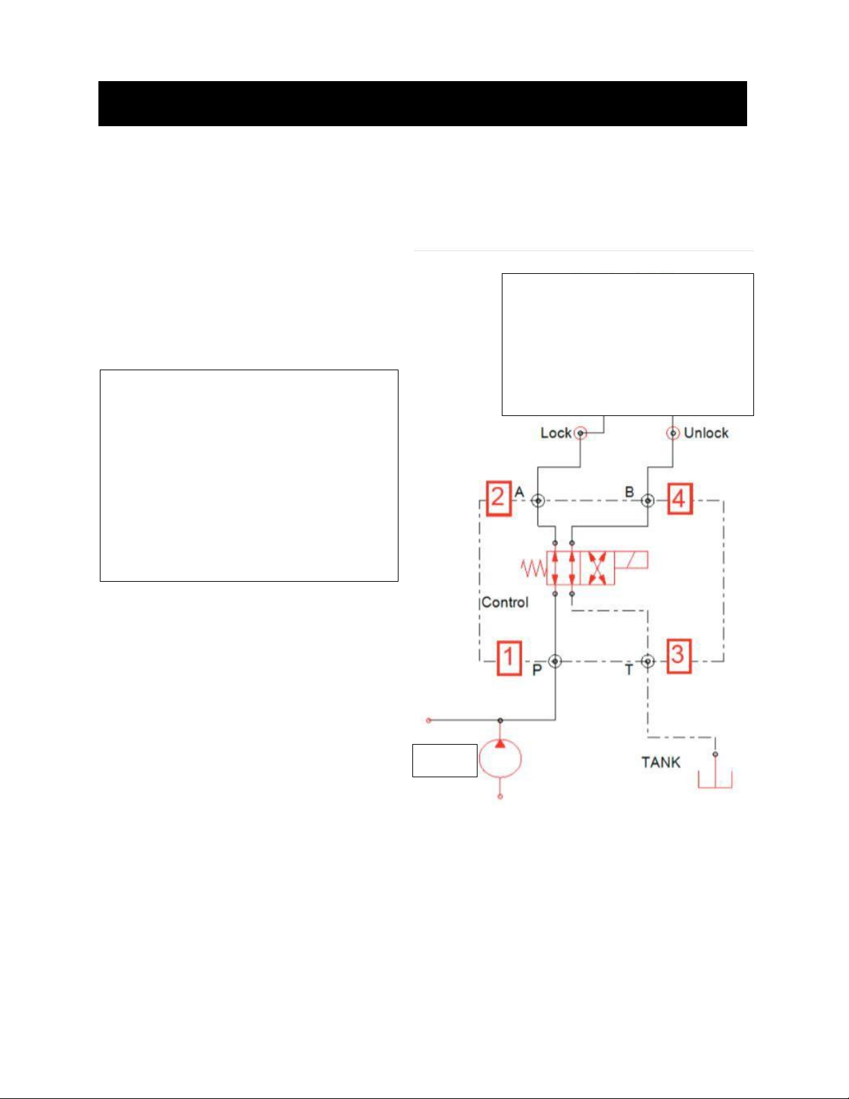
Control Valve
Locate a good mounting location for the coupler lock valve, near the pilot pump outlet line.
The mount can be bolted or welded in place.
Locate the hose at the pump outlet port. Disconnect the hose at the pump and install the tee.
Reconnect the existing hose to one end of the tee. Measure the appropriate length of hose to
connect the “P” port on the valve to the pilot line tee.
Locate an existing JIC 06 (3/8”) tank line. Disconnect the existing hose and install tee.
Reconnect the existing hose to one end of the tee. Measure the appropriate length of hose to
connect the “T” port on the valve to the tank line tee and cut to length. Install the hose ends
and connect the hose.
Measure the required length of hose to reach from the valve mounting location to the blocks
on the stick.