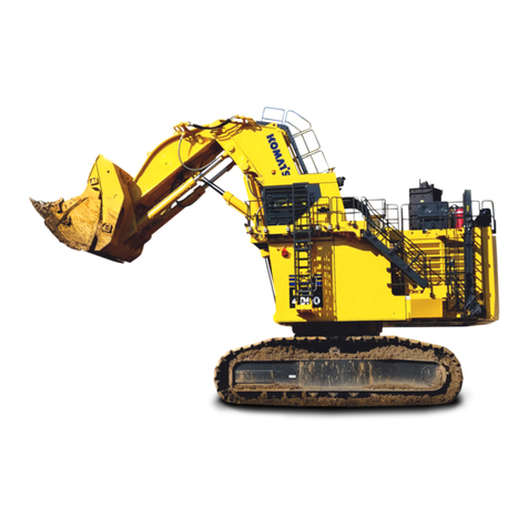
Komatsu PC3000-6 Manual

AS PC3000-6 rev7
Edition October 2005 1
General Assembly Procedure
Hydraulic Mining Shovel PC3000-6

Assembly Procedure PC3000-6
All stated information corresponds
to the present development and is
subject to possible future changes
without prior notice.
AS PC3000-6 rev7
Edition October 2005 2

Assembly Procedure PC3000-6
GENERAL CONTENT PAGE
1. General................................................................................................5
1.1 Delivery of the Excavator .................................................................. 5
1.2 Assembling of the Excavator............................................................. 5
1.3 Transportation and Lifting.................................................................. 7
1.4 Manpower / Assembly Time*............................................................. 9
1.5 Assembly Site Requirements .......................................................... 11
1.6 Space and Placing Requirements................................................... 15
1.7 Preparation for Assembly................................................................ 15
1.8 Basic Measurements (Z 24015) ...................................................... 17
1.9 Transport Dimensions and Weights (as example)........................... 17
1.10 Illust. Configuration of Components on Erection Site...................... 19
2.0 Assembly sequence.......................................................................19
2.1. Assembly of Undercarriage (Z 24016; Z 24017; Z 24018)...................... 21
2.1.1 Assembly....................................................................................................21
2.1.2 Determination of the tightening torque .......................................................25
2.1.3 Final works .................................................................................................29
2.2 Assembly of Superstructure onto the Undercarriage (Z 9031a).............. 31
2.3. Mounting of Boom and Boom cylinders(Z 9032; Z 20949)...................... 35
2.4. Mounting of Fuel Tank (Z21924)............................................................. 37
2.5 Mounting of Hydraulic access Ladder (Z 24022) .................................... 39
2.5. Mounting of Cab Base (Z 24023)............................................................ 41
2.6. Mounting of Counterweight (Z 24024) .................................................... 43
2.7. Mounting of Handrails, Steps and Gratings (Z 24025)........................... 45
2.8. Mounting of Cab (Z 24029)..................................................................... 47
2.9 Pre-checks prior Initial Start up............................................................... 49
2.10 Mounting of Stick.................................................................................... 53
2.10.1 Backhoe Attachment (Z 24030) ......................................................................53
2.10.2 Bullclam Bucket Attachment (Z 20950; Z 20951; 20952)................................55
2.11 Assembly of the bucket to the stick......................................................... 61
2.11.1 Assembly of the backhoe to the stick (Z 23005).............................................61
2.11.2 Assembly of the bullclam bucket to the stick (Z 20953)..................................63
2.12 Mounting of the Pin Seals....................................................................... 67
2.12.1 Backhoe (Z 23006)..........................................................................................67
2.12.2 Bullclam bucket (Z 21963) ..............................................................................69
2.13 Putting the Central Lubrication System into operation (Z 24031) ........... 71
2.14 Standard Application Torque Chart......................................................... 73
2.14.1 Metric standard thread....................................................................................73
2.14.2 Metric fine thread ............................................................................................75
2.14.3 Torque Chart for Flange Joints .......................................................................76
AS PC3000-6 rev7
Edition October 2005 3


Assembly Procedure PC3000-6
AS PC3000-6 rev7
Edition October 2005 4

Assembly Procedure PC3000-6
1. General
1.1 Delivery of the Excavator
The excavator is being delivered disassembled into its main
components. For the correct dimensions and weights please refer to
the packing list of your machine.
For assembling the excavator follow the instructions in this manual.
1.2 Assembling of the Excavator
ã
•Personnel entrusted with work on the machine must have read
the Assembly Manual, the Operation,- Lubrication- and
Maintenance Manual and in particular the section on safety
before beginning work. Reading the instructions after work has
commenced is too late.
If there are any questions concerning the assembling procedure,
contact your local Service Center.
Prior to first operation, inspect the excavator thoroughly with the
Service Engineer responsible for the erection of the machine. Check
all fluid levels according to the Lubrication and Maintenance Schedule.
Damages and defects caused by incorrect operation and maintenance
are not covered by the manufacturers guarantee.
)
•If the excavator is equipped with a fire suppression system,
make sure that the system is ready for operation.
AS PC3000-6 rev7
Edition October 2005 5

Assembly Procedure PC3000-6
AS PC3000-6 rev7
Edition October 2005 6

Assembly Procedure PC3000-6
ã
•Before assembling/disassembling, lifting or transporting this
excavator contact your local Service Center for all the
necessary instructions for safe and economic assembling/
disassembling, lifting and transportation procedures of your
excavator.
The sequence of assembly as shown in this Manual. Disassembling is
basically the reverse order of the assembling procedure.
1.3 Transportation and Lifting
The transport dimensions and weights of the excavator’s components
are listed in this manual are for general information only. For the
correct dimensions and weights please refer to the packing list of your
machine.
Observe the operating permits of the low-bed trailers used for
transportation. They contain the permissible load, loading width and
height.
ã
•Observe the federal, state and local laws and regulations for
transportation of heavy units. Know the safety rules and laws
before you transport this Excavator.
•Make sure the flat-bed trailer and the components of the
Excavator are equipped with the correct safety devices.
•Secure the Excavator and all components transported on the
trailer against movement.
•Use exclusively approved handling equipment.
•When lifting components make sure that the handling elements
do not cause damage to the component.
•Secure the components safely before removing the lifting
straps, ropes or chains.
AS PC3000-6 rev7
Edition October 2005 7

Assembly Procedure PC3000-6
AS PC3000-6 rev7
Edition October 2005 8

Assembly Procedure PC3000-6
ã
•Wear safety clothing, goggles, respirator and other safety
devices, whenever working conditions make this necessary.
•Provide hoists of sufficient capacity to lift heavy units. Refer to
the weight specifications.
•Be sure to observe the instructions in the ”Assembly
Procedure Manual”.
•Lifting gear, tools and other suspension systems must be in
good condition and of sufficient lifting capacity.
•Be sure hydraulic cylinders and attachment components are
properly supported from hoist and securely fastened, before
removing supporting pins.
•Floors must be clean and dry. After draining operations be sure
all spillage is cleaned up.
1.4 Manpower / Assembly Time*
Customer 1 Electrician
4 Fitters/ Mechanics
Supervision Dealer or
Komatsu Mining Germany 1 Service Engineer
Days
Assembly Time* 6**
*Dependent on mine conditions (shifts, weather, ...)
**Without testing and customer acceptance.
AS PC3000-6 rev7
Edition October 2005 9

Assembly Procedure PC3000-6
AS PC3000-6 rev7
Edition October 2005 10

Assembly Procedure PC3000-6
1.5 Assembly Site Requirements
Assembly Site Requirements:
−Well leveled and compacted ground approx. 150 x 150 ft/50 x 50 m
−A container to store the tools, to keep the paper work and for sheltering
−2 mobile cranes 90 metric tons
−1 small crane, load capacity approx. 25 metric tons
No. Qty. Specification Designation
1 01 6 metric tons Telescopic fork lift
2 04 6 metric tons Chain pull
3 04 35 metric tons Shackles
4 04 5 metric tons t Shackles
5 04 1 metric ton Shackles
6 04 each M10/12/14/16/18/20 Eye bolts
7 04 30 metric tons - 8 m length Ropes
8 04 25 metric tons - 8 m length Ropes
9 04 16 metric tons - 8 m length Ropes
10 04 12 metric tons - 8 m length Ropes
11 01 ∅50 mm x 1000 mm length Pry bar
12 01 ∅50 mm x 2000 mm length Pry bar
13 01 5 kg Large hammer
14 60 300 x 300 x 1000 mm Wooden blocks
15 10 300 x 300 x 2500 mm Wooden blocks
16 02 10 metric tons Hydraulic jacks
17 02 50 metric tons Hydraulic jacks
18 01 50 m Cable drum
19 01 each 6/7/8/9/10/12/13/14/15/17/19
mm 22/24/27/30/32 mm Combination spanner
20 01 each 41/46/50/55/60/ 65 mm Single ended open spanner
21 01 each 7 mm up to 55 mm Double end open spanner
22 01 3/4” Impact wrench
23 01 1/2” Impact wrench
24 01 1/2” Ratchet
25 01 3/4” Ratchet
26 01 each 13 mm up to 19 mm Sockets for ½” Ratchet
27 01 24 mm up to 36 mm Socket for 3/4” Ratchet
28* 01 Only useable with torque wrench
(PN793 374 73)
(refer to page 28)
Tightening tool for bolts center
section side frame connection
(PN793 376 73) including special
tightening nut
This tool is required to ensure:
- that the reaction torque is
supported at the bottom of the
neighbor bolt
- that no bending moment effects
the neighbor bolt
29 01 0 – 9900 Nm
(refer to page 28) Hydraulic torque wrench
(PN793 374 73)
30 1.2 l; till 700 bar
(refer to page 28) Electric hydraulic power pack
(PN793 375 73)
AS PC3000-6 rev7
Edition October 2005 11

Assembly Procedure PC3000-6
Yazaki Connector Set
No. Qty. Designation Part No.
1 2 Connector 3-pole 891 040 40
2 2 Connector 3-pole 891 032 40
3 2 Connector 2-pole 891 039 40
4 2 Connector 2-pole 891 031 40
5 2 Connector 1-pole 891 038 40
6 2 Connector 1-pole 891 030 40
AS PC3000-6 rev7
Edition October 2005 12

Assembly Procedure PC3000-6
Qty. Specification Designation
31 01 30/32/36/41/46/55/65/75 mm Sockets HD for hydr. torque wrench
32 01 Range 0 - 250 Nm
T
orque wrench ⇒drive ½”
33 01 Range 250 - 600 Nm
T
orque wrench ⇒3/4”
01 Range to 140 Nm Cordless Impact Wrench 1/2 “
P/N 793 828 73
34 01 Hand drill
35 01 5, 6, 8, 10, 12, 14 mm Screw driver sockets for 1/2” drive
36 01 14, 17, 19 mm Screw driver sockets for 3/4” drive
37 01 2 up to 19 mm Hex keys (Allen keys) L-type
38 01 Electric welding machine
39 01 Lights for the illumination of the working
area
40 01 Hand lamp
41 07 600 bar Pressure gauge
42 03 60 bar Pressure gauge
43 03 25 bar Pressure gauge
44 01 15 bar Pressure gauge
45** 02 Multi-meter P/N 232 619 40
46 02 Cable set P/N 232 496 40
47 01 0 - 2500 min-1 Contact less revolution indicato
r
48 02 1,5 mm² 30 m Cables with connectors
49 01 from M6 - M 36
T
hread cutting set
50 01 Level gauge
51 01
T
est adapter proportional/solenoid valves
P/N 232 537 40 / 232 538 40
52 01 Set
Y
azaki connectors (refer to table )
53 01 Set Screw drive
r
54 01 Side cutte
r
55 01
T
ip plie
r
56 01 Combination plie
r
57 01 Pipe plier
*
ã
•If the specific tool and the prescribed assembly procedure are
not used for assembling the crawler carriers to carbody KMG
will not carry the warranty for the undercarriage!
** If available an electronic testing device for pressure, voltage and RPM,
similar Hydrotechnic System 6000
AS PC3000-6 rev7
Edition October 2005 13

Assembly Procedure PC3000-6
AS PC3000-6 rev7
Edition October 2005 14

Assembly Procedure PC3000-6
1.6 Space and Placing Requirements
On the following page, the components are indicated in their approx.
dimensions.
They are unloaded in a way that a min. space of 1 meter (3 ft) is left
between the components, and that there is enough space for the
trucks and the cranes.
1.7 Preparation for Assembly
Unload all components so that no more move is necessary!
All pins, bushings, borings, bearings and contact surfaces of
components must be clean
Torque values are listed in section 6.9 of the Lubrication- and
Maintenance Manual - unless being listed in this Assembly Procedure
Booklet.
Obey all applicable safety and local regulations strictly!
Ensure correct lifting procedures and ensure use of adequate lifting
gears!
High voltage installation works must be carried out by authorized
specialists only.
AS PC3000-6 rev7
Edition October 2005 15

Assembly Procedure PC3000-6
Z 24015
AS PC3000-6 rev7
Edition October 2005 16

Assembly Procedure PC3000-6
1.8 Basic Measurements (Z24015)
1.9 Transport Dimensions and Weights (as example)
AS PC3000-6 rev7
Edition October 2005 17

Assembly Procedure PC3000-6
AS PC3000-6 rev7
Edition October 2005 18

Assembly Procedure PC3000-6
1.10 Illust. Configuration of Components on Erection Site
2.0 Assembly sequence
Subject Illustr. Page
1. Assembly of Undercarriage (Z 24017) 21
2 Assembly of Superstructure onto the Undercarriage (Z 9031a) 31
3. Mounting of Boom and boom cylinders (Z 9032) 35
4. Mounting of Fuel Tank (Z 21924) 37
5 Mounting of Hydraulic access Ladder (Z 24022) 39
5. Mounting of Cab Base (Z 24023) 41
6. Mounting of Counterweight (Z 24024) 43
7. Mounting of Handrails, Steps and Gratings (Z 24025) 45
8. Mounting of Cab (Z 24029) 47
10. Mounting of Stick /Stick cylinders (Z 24030) 51
11. Assembly of the bucket to the stick (Z 23005) 59
12. Mounting of the Pin Seals (Z 23006) 65
13. Putting the Central Lubrication System
into operation (Z 24031) 69
AS PC3000-6 rev7
Edition October 2005 19

Assembly Procedure PC3000-6
AS PC3000-6 rev7
Edition October 2005 20
Other manuals for PC3000-6
1
Table of contents
Other Komatsu Construction Equipment manuals

Komatsu
Komatsu Avance Loader WA900-3 Manual

Komatsu
Komatsu XT430-3 Manual

Komatsu
Komatsu D31EX -22 Manual

Komatsu
Komatsu 830E-1AC Manual

Komatsu
Komatsu PC3000-6 Manual

Komatsu
Komatsu D61EXi-24 Manual

Komatsu
Komatsu XT430-2 Manual

Komatsu
Komatsu D65EXi-18 Manual

Komatsu
Komatsu WB93S-5 F50003 Manual

Komatsu
Komatsu D85EX-18 Manual

Komatsu
Komatsu 450FXL-1 Manual

Komatsu
Komatsu WA95-3 Manual

Komatsu
Komatsu GD755-5R User manual

Komatsu
Komatsu WA250-6 Install guide

Komatsu
Komatsu Galeo BR380JG-1 Manual

Komatsu
Komatsu Boss D87E-2 Manual

Komatsu
Komatsu 860E-1KT Manual

Komatsu
Komatsu BR380JG-1E0 Install guide

Komatsu
Komatsu GD555-5 Manual

Komatsu
Komatsu D37EXi-24 Manual