Publication: WBHLP08152022
Copyright 2022
CAUTION! Indicates a hazardous situation or
unsafe practice which, if not avoided,
could result in minor or moderate
injury or property damage.
WARNING! Indicates a hazardous situation
which, if not avoided, could result in
serious injury or death.
DANGER! Indicates a hazardous situation
which, if not avoided, will result in
serious injury or death.
3
SAFETY
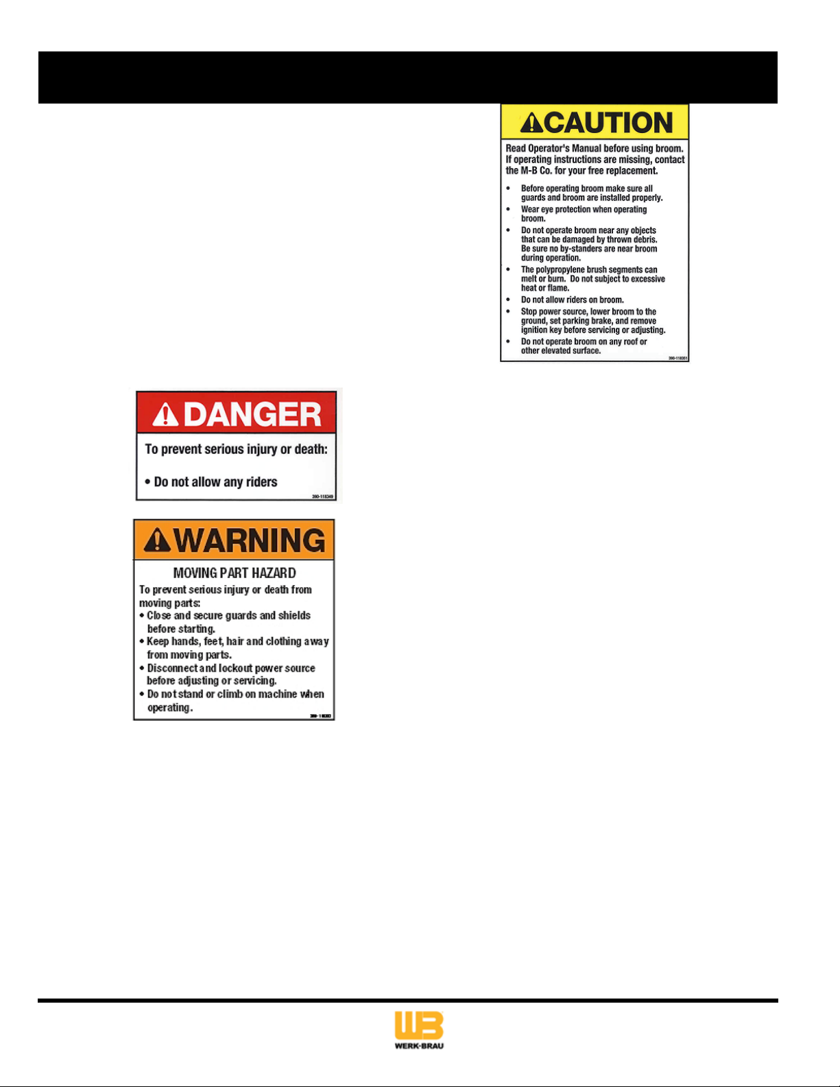
SAFETY ALERTS
Signal words and alert symbols notify of important safety precautions.
SAFETY DECALS
Although reading this manual and the safety instructions it contains
will provide you with the necessary basic knowledge to operate this
equipment safely and eectively, we have placed several safety
labels on the unit to remind you of this important information while
you are operating your unit.
All DANGER, WARNING, CAUTION, and instructional messages on
your unit should be carefully read and obeyed. Bodily injury can result
when these instructions are not followed. The information is for your
safety and it is important.
These labels will act as a constant visual reminder to you, and others
who may use the equipment, to follow the safety instructions
necessary for safe, eective operation.
If any of these labels are lost or damaged, replace them at once. See
your local dealer for replacements.
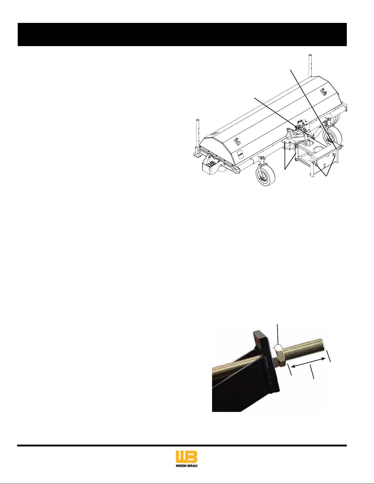
PRE-START GUIDELINES
• Install any covers or guards which may have been removed for
shipping purposes.
• Before starting equipment, walk around equipment, making a
visual inspection that all safety devices are properly installed and
secured.
• Check that all hardware, fasteners, hydraulic ttings, etc. are in
good condition and properly fastened. Replace any fatigued or
damaged items with proper replacements.
• Personnel who are not required to be in the work area should be
kept away. Never start the equipment unless you are absolutely
certain that everyone in the area is clear of the machine and
aware it is being started.
• Follow the manufacturer’s recommended start-up procedure.
OPERATION GUIDELINES
Read, understand and follow all instructions in the manual and on
the unit before starting.
NOTE: All reference to left, right, front or rear are given from the
operator position and facing forward.
• To avoid serious injury or death, do not modify equipment. Any
modications made to equipment can be dangerous and can void
equipment warranty.
• Never defeat a safety device to make a task easier.
• Always wear proper apparel when operating equipment; safety
glasses, face shield or goggles, ear protection, and dust mask. Tie
hair back. Never wear loose clothing or jewelry that could get
caught in moving parts.
• Never operate equipment with covers or guards removed. Rotating
parts can cause severe injury. Keep hands, feet, hair, jewelry and
clothing away from all moving parts.
• Only allow responsible adults who are familiar with the instructions,
to operate the unit (local regulations can restrict operator age).
• Clear the area of objects such as rocks, toys, wire, etc., which
could be picked up and thrown.
• Be aware of surroundings. Be sure the area is clear of other
people, bystanders or pets. Stop unit if anyone enters the area.
Indicates a hazardous situation
Indicates a hazardous situation
Indicates a hazardous situation
or unsafe practice which, if not