ATD Tools ATD-7484 Instructions for use

Printed in China
ATD7484_ATD7485_rev_0417
Model ATD-7484
Model Number
ATD-7484
ATD-7485
Operating Instructions & Parts Manual
Capacity
2 Ton
2 Ton
Heavy Duty
Engine Cranes
(Foldable Legs)
Model ATD-7485
WARNING: This product may contain chemicals, including lead, known to the State of California to cause cancer,
birth defects or other reproductive harm. Wash hands after handling.
Made in China to ATD Tools, Inc. Specications
Visit us at www.atdtools.com

Save these instructions. For your safety, read and understand the information contained within. The owner and
operator shall have an understanding of this product and safe operating procedures before attempting to use this
product. Instructions and Safety information shall be conveyed in the operators native language before use of this
product is authorized. Make certain that the operator thoroughly understands the inherent dangers associated with
the use and misuse of the product. If any doubt exits as to the safe and proper use of this product as outlined in this
factory authorized manual, remove from service until which time it is clear. Inspect before each use. Do not use
if broken, bent, cracked or otherwise damaged parts are noted. If the crane has been or suspected to have been
subjected to a shock load, discontinue use until checked out by an authorized factory service center. Owners and
operators of this equipment shall be aware that the use and subsequent repair of this equipment may require special
training and knowledge. It is recommended that an annual inspection be done by TXDOL¿HGSHUVRQQHODQG that any
missing or damaged parts, decals, warning / safety labels or signs be replaced with factory authorized replacement
parts only. Any crane that appears to be damaged in any way, is worn or operated abnormally should be removed
from service immediately until such time as repairs can be made.
PRODUCT DESCRIPTION
ATD Tools Engine Cranes are designed to safely lift and lower rated capacity engines. It is an aid in the removal and
installation of automotive and light truck engines. Welded steel tube construction, heavy duty chains and safety
hooks,steelcastersand wheelsalong withcompliance withthe latestASME /ANSI - PALD standardsensuresafety,
strength and stability. Model ATD-7485 is a foldable, space saver design. Each has air actuated option.
2
SPECIFICATIONS
Model Boom
Position Capacity Min. Hook
Height Max. Hook
Height Boom Length
ATD-7484
ATD-7484
ATD-7485
62-1/2” to 89-1/2”
78-1/2”
29” to 33-7/8”
37-7/8”
34-5/8” to 53-1/8”
30-3/8”
57”
57”
(73” folded)
3-1/2”
5”
3-1/2”
3-1/2”
266.25 lbs.
266 lbs.
Model Base
Length
Base
Width
(Front)
Base
Width
(Rear) Height
Wheel
Diameter
(Front)
Wheel
Diameter
(Rear) Weight
1 2 Ton 18-3/8" 69-1/4" 48-3/4"
2 1-1/2 Ton 14" 75-1/4" 57-3/4"
3 1 Ton 9-1/4" 81-1/4" 66-3/4"
4 1/2 Ton 5" 86-1/2" 76-3/4"
ATD-7485
1 2 Ton 0" 59-1/4" 48-5/8"
2 1-1/2 Ton 0" 63" 55-5/8"
3 1 Ton 0" 66-5/8" 62-7/8"
4 1/2 Ton 0" 70-1/2" 69-7/8"

Hook
Rear Caster
Front Extension Legs Front Caster
Boom Extension
Boom
Hydraulic
Unit (jack)
Base
Handle
Braces
Upright
Rear Exten-
sion Legs
Front Legs
Hook
Hydraulic
Unit (jack)
Caster
Braces
Boom
Upright
Handle
Base
Boom Extension
Crane
Handle
Middle
Wheels
Front Wheel
Figure 1- Model ATD-7484 components
Figure 1- Model ATD-7485 components
3

BEFORE USE
1. Inspect crane before each use. Do not use if bent,
broken or cracked components are noted. Ensure
that casters/wheels and boom move freely. Check
for and tighten any loose assemblies.
2. Verify that the product and the application are
compatible, if in doubt call for Technical Service
(888) 332-6419.
3. Before using this product, read the owner's manual
completely and familiarize yourself thoroughly with
the product and the hazards associated with its
improper use.
3. Open the release valve by turning the release valve
lever
counter-clockwise (no more than 1/2 full turn).
4.Withramfullylowered,removeoil¿llerplugandpump
handle 6 to 8 full strokes. This will help release any
trappedair within thereservoir. Ensure the oillevel is
justbelow the oil¿OOer hole. Reinstalltheoil ¿OOerplug.
&ORVHUHOHDVHYDOYHE\WXUQLQJLWFORFNZLVH¿UPOy.
5.Check to ensure that crane rolls freely, that the pump
andreleasevalve operate smoothly. Raiseandlower
the unloaded crane throughout the lifting range be-
fore putting into service.
6. Replace worn or damaged parts and assemblies
with Factory Authorized Replacement Parts only.
Lubricate as instructed in Maintenance Section.
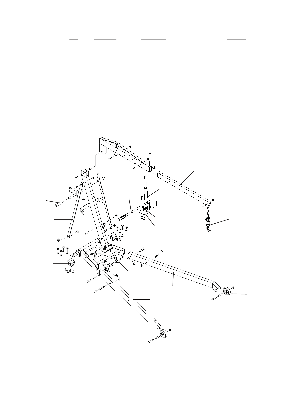
4Figure 3 - Assembly Illustration for model ATD-7484
ASSEMBLY
For ModelATD-7484: (See Figure 1)
1. Attach casters (#15) to rear extension legs (#24)
with M8x20 bolts, washers and nuts (#29, 33 &
34).
2. Slide front extension legs (#14) and rear extension
legs(#24)intobaseframe (#11),securewithM12x25
bolts (#13) in frame, tighten bolts.
Note: Do not tighten any bolts unless told to. Never
extend beyond mark on leg. Extend each leg extension
equal distance from frame.
3. Place post (#2) on the base frame and secure with
0[EROWV/HDYHEROWV¿QJHUWLJKW
4. Attach braces (#18) on each side of post at top and
secure with M12x100 bolt and nut (#4 & 19). Place
bottomofbraces on insideof base frame securewith
M12x90 bolts and nuts (#31 & 19).
5. Attach bracket (#32) to hydraulic unit (#1) with
M10x30 bolts, washers and nuts (#6, 25 & 26).
Then attach to post using M16x75 bolt and nut (#10
& 12).
6.Placeboom (#7) on topof post, secure withM20x120
bolt and nut (#3 & 20). Pump hydraulic unit using
handle (# 21) until ram is approximately 2" above.
Placefront mounting bracketon boom, ontop of ram
and secure with M16x90 bolt and nut (#9 & 12).
7. Slide boom extension (#8) to boom (#7), make sure
the slot for chain (#17) faces down and secure with
M16x90bolt and nut(#9 & 12). 4 positionsavailable:
1/2 ton, 1 ton, 1 1/2 ton and 2 ton.
8. Insert chain and hook(#17) to boom extension (#8)
with M12x75 bolt and nut (# 30 & 19).
Note: Checkall fasteners for tightness, including those
pre-assembled at the factory. Tighten where required.
Do not load beyond rated capacity.
WARNING
!
6WXGy, understand, and follow all instructions
provided with and on this device before operating
this device.
'RQRWH[FHHGUDWHGFDSDFLW\IRUHDFKERRPSRVL-
tion.
8VHWKHGHYLFHRQO\RQDKDUGOHYHOVXUIDFH
2QO\XVHFKDLQVDQGVOLQJVZLWKDFDSDFLW\HTXDO
to or greater than that of the crane.
,IORDGHGFUDQHPXVWEHPRYHGPDNHFHUWDLQWKDW
load is stable, is in lowest possible position and is
moved over a smooth, hard level surface.
Avoid shock loads caused by the rapid opening
and closing of release valve.
6KRFNORDGVPD\FDXVHWKHORDGWRVZLQJFDXV-
LQJWKHFUDQHWRÀLSYLROHQWOy, bend or break.
(QVXUHWKHERRPLVIXOO\ORZHUHGEHIRUHFKHFNLQJ
RUDGGLQJÀXLGWRWKHK\GUDXOLFXQLW
1HYHUH[WHQGERRPH[WHQVLRQEH\RQGOHJH[WHQ-
sion (Model ATD-7484).
'RQRWVWDQGRYHUORDGHGERRPQRULQLWVLQWHQGHG
line of travel.
'RQRWXVHDGDSWHUVRUDFFHVVRULHVWKDWDUHQRW
provided initially.
Do not use the device for any purpose other than
that for which it is intended.
1RDOWHUDWLRQVVKDOOEHPDGHWRWKLVGHYLFH
Failure to heed these markings may result in
personal injury and/or property damage.

5
Figure 4 - Assembly Illustration for model ATD-7485
ASSEMBLY (continued)
For Model ATD-7485: (see Figure 2)
1. Attach caster assembly (# 23) to base frame (# 24)
using M8x16 bolts, washers and nuts (# 14, 21 & 22).
2. Install 3.5 " middle wheels (# 33) to base frame (# 24)
using M8x60 bolts, rod cover, washers and nuts (#
31, 32, 22 & 21).
3. Attach two front legs (# 27 & 35) to base frame (# 24)
using M16x85 bolts, washers and nuts (# 43 & 9).
Then secure the legs with stop bar and pin (#25 & 34)
to the front hole of the legs.
4. Attach upright (# 18) to base frame using M12x80
bolts, washers and nuts (# 20 & 10). Upright must
lean towards the rear of the base frame as shown.
/HDYHQXWV¿QJHUWLJKW
5. Attach braces (# 17) to upright(# 18) with M12x80
EROWZDVKHUDQGQXW/HDYHQXW¿QJHU
tight.
6. Attach braces (#17 to inside of base frame (24) using
M12x35 bolts, washers and nuts (# 20 & 2).
Note: Braces assemble to inside of base frame.
7. Tighten upright to base frame, braces to upright, and
braces to base frame bolts.
8. Attach hydraulic unit (# 41) to the bracket (# 39) using
M10x30 bolts, washers and nuts ( # 38, 37 & 36).
Then position to mounting ears on post, attach using
M16x75 bolt, washer and nut (# 10 & 9).
To fold for storage:
a. Remove stop bar and pin (# 25 & 34).
b. Raise leg until it leans on the
legs support bracket (# 19).
Note: Handle of hydraulic unit must face the front of
the base frame as shown. Tighten nut. Lean hydraulic
unit assembly back against post.
9. Connect boom (# 8) to upright (# 18) using
M20x100 bolt, washer and nut (# 12 & 11).
10. Hold boom and pivot hydraulic unit out away
from upright and position ram between mounting
brackets on boom. Attach hydraulic unit to boom
with M16x75 bolt, washer and nut (# 10 & 9).
Tighten nuts.
11. Slide boom extension (# 4) into boom and secure
in retracted position using M12x70 bolt and nut (#
7 & 2). 4 positions available: 1/2 ton, 1 ton, 1 1/2
ton and 2 ton.
12. Slide square washer (# 5) into boom, sesure us-
ing M8x16 bolt and washer (# 6, 22)
13. Insert hook (# 1) to boom extension using
M12x60 bolt, washer and nut (# 3 & 2).
14. Attach legs support bracket (# 19) to upright (#
18) with M6x10 bolts (# 42).
15. Attach handle to upright (# 18) with M8x16 bolts
(# 14).
This manual suits for next models
1
Table of contents
Other ATD Tools Construction Equipment manuals