Werner Dosiertechnik POOLKLAR Touch XL User manual

WERNER Dosiertechnik
_________________________________________________________________
Technische Änderungen vorbehalten
--------------------------------------------------------------------------------------------------------------------------------------------------------------------------------------------------------------
Hettlinger Straße 17 Tel. +49 (0) 8272/ 98697- 0 www.werner-dosiertechnik.de
Version vom 18.April 2011 noch ned freigegeben! Korrekturlesung
Auto-control system
for private pools
POOLKLAR Touch XL
Mess-, Regel- und Dosiertechnik für pH-Regulierung und Desinfektionsmittel

WDT POOLKLAR Touch XL
Original Bedienungsanleitung in deutsch - Version (V1.1 –2012_01_09) 2/24
Inhaltsverzeichnis
1 Notes to this manual ................................................................................................... 4
1.1 scope of application............................................................................................... 4
1.2 Target group ........................................................................................................ 4
1.3 Keeping of the manual........................................................................................... 4
1.4 Further information ............................................................................................... 4
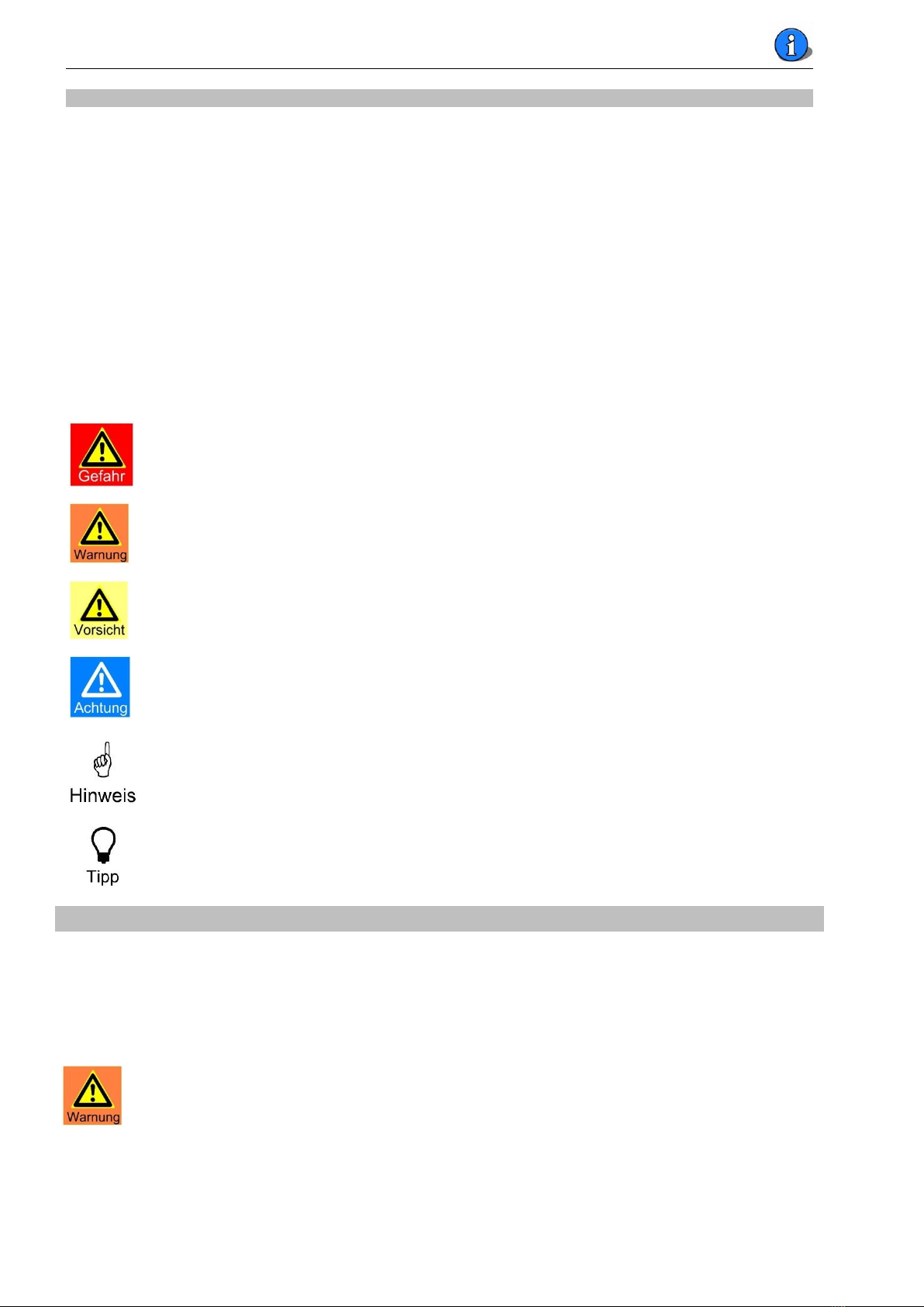
1.5 Used symbols ....................................................................................................... 4
2 Safety aspects............................................................................................................ 4
2.1 Intended use ........................................................................................................ 4
3 Delivery scope –Description ........................................................................................ 5
3.1 Delivery scope ...................................................................................................... 5
3.2 Transport damage................................................................................................. 5
3.3 Identification of the device ..................................................................................... 5
3.4 Device description................................................................................................. 5
4 Installation ................................................................................................................ 6
4.1 Place of installation ............................................................................................... 6
4.2 Tapping points for measuring water......................................................................... 6
4.3 Installation proposal .............................................................................................. 6
5 Commissioning........................................................................................................... 7
5.1 Setting of the Control parameters –see for this page 22 “Commissioning form” ........... 7
5.2 pH-Electrode ........................................................................................................ 7
5.3 Cleaning glass beads ............................................................................................. 7
5.4 Measuring water flow............................................................................................. 7
5.5 Dosing pump heads............................................................................................... 7
5.6 Chemicals ............................................................................................................ 7
5.7 Switch off at backwash and vacuuming .................................................................... 8
6 Electrical connections .................................................................................................. 8
6.1 To open and close the housing................................................................................ 8
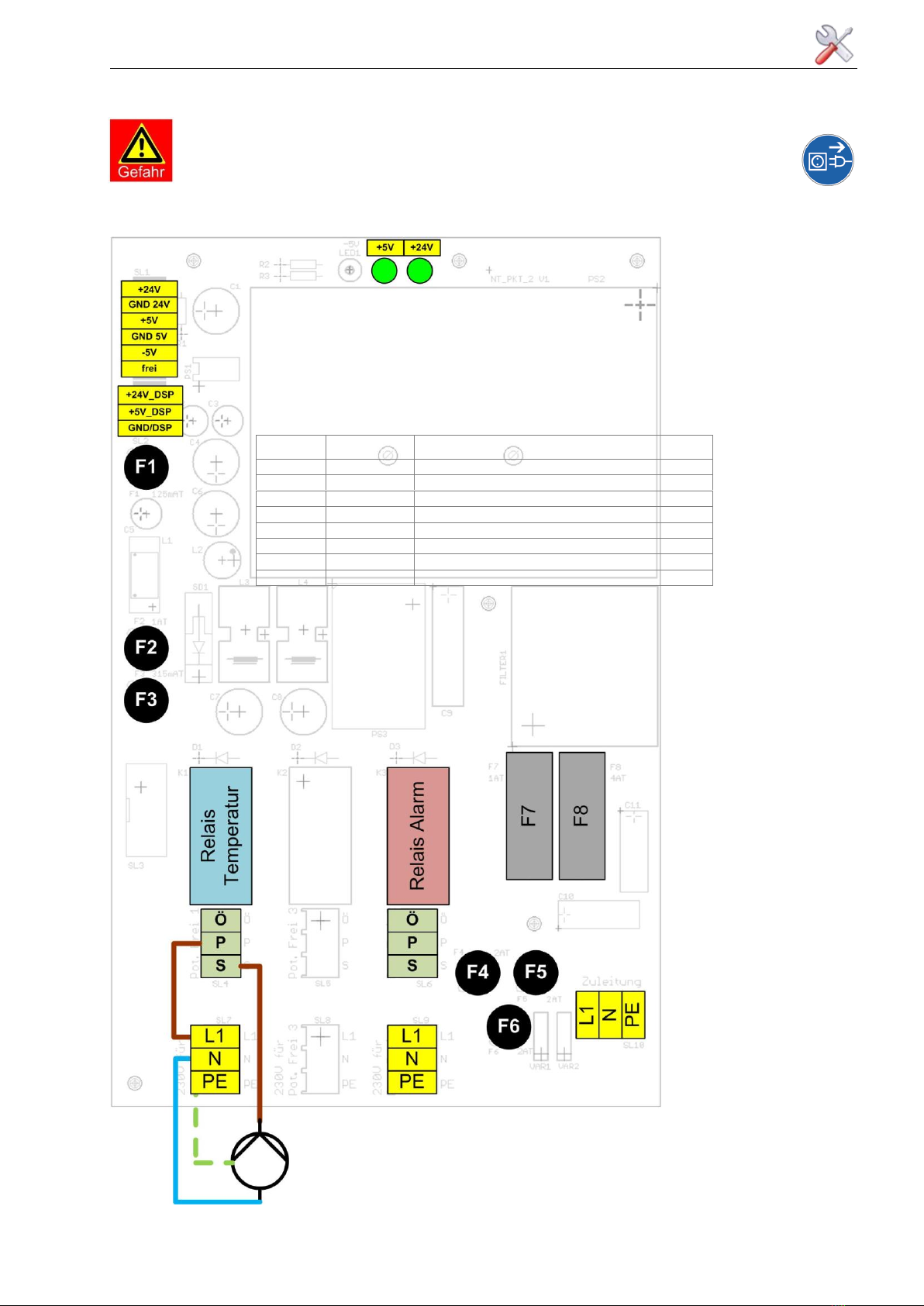
6.2 Wiring plan........................................................................................................... 9
6.2.1 The power board NT_PKT_2 –fuses, relay............................................................. 9
6.2.2 The I/O- Board IO_PKT_2...................................................................................10
6.2.3 The amplifier MV_PKT_2 ....................................................................................10
6.3 OPTIONS ............................................................................................................12
6.3.1 OPTION Temperature.........................................................................................12
7.3.2 OPTION Filter pressure.......................................................................................12
7 Operation of the Touch display ....................................................................................13
7.1 Operation Indication and Programmes ....................................................................14
7.1.1 Normal operation ..............................................................................................14
7.1.2 QuickInfo .........................................................................................................14
7.1.3 Dosing delay.....................................................................................................14
7.1.4 Start routine.....................................................................................................14
7.1.5 Alarm ..............................................................................................................14
7.2 Main menu ..........................................................................................................15
7.2.1 Main menuSettings ........................................................................................15

WDT POOLKLAR Touch XL
Original Bedienungsanleitung in deutsch - Version (V1.1 –2012_01_09) 3/24
7.2.1.1 Main menuSettings pH ............................................................................ 15
7.2.1.2 Main menuSettings mV (Disinfection) ....................................................... 16
7.2.1.3 Main menuSettings dosing capacity .......................................................... 16
7.2.1.4 Main menuSettings temperature ............................................................. 16
7.2.1.5 Main menuSettings pressure................................................................... 17
7.2.1.6 Main menuSettings Dosing delay .............................................................. 17
7.2.1.7 Main menuSettings system ...................................................................... 17
7.2.1.8 Main menuSettings system
pass word ................................................... 17
7.2.1.9 Main menu Settings system
network ..................................................... 18
7.2.2 Main menu calibration ................................................................................... 18
7.2.2.1 Main menu calibration pH- electrode ......................................................... 18
7.2.2.2 Main menu calibration
redox- electrode..................................................... 19
7.2.3 Main menu Service ....................................................................................... 19
7.2.3.1 Main menu Service output test.............................................................. 19
7.2.3.2 Main menu Service input test............................................................... 19
7.2.3.3 Main menu Service Info ........................................................................ 19
7.2.3.4 Main menu Service event log list ............................................................ 19
8 Maintenance............................................................................................................. 20
8.1 Filter ................................................................................................................. 20
8.2 pH-electrode....................................................................................................... 20
8.3 Injection valves .................................................................................................. 20
8.4 Dosing heads...................................................................................................... 21
8.5 Redox-electrode.................................................................................................. 21
9 Diagnosis and troubleshooting................................................................................... 21
9.1 check of dosing function....................................................................................... 21
9.2 Check of the electrodes........................................................................................ 21
10 taking out of service –hibernation - storage............................................................... 21
11 Technical data ........................................................................................................ 21
12 Commissioning form................................................................................................ 22
13 Spare parts list ....................................................................................................... 23
14 Own notes ............................................................................................................. 24

WDT POOLKLAR Touch XL
Original Bedienungsanleitung in deutsch - Version (V1.1 –2012_01_09) 4/24
1 Notes to this manual
1.1 scope of application
This manual describes the installation, commissioning and operation of the unit. This manual is guilty for
the POOLKLAR Touch XL from version -> see foot print.
1.2 Target group
Only instructed persons shall operate this unit. Works on electric or water side should only be executed
by skilled persons.
1.3 Keeping of the manual
All manuals must be kept near to the unit and must be accessible anytime to any operating persons.
1.4 Further information
Further information as selection needs for the operation parameters you get from your dealer.
1.5 Used symbols
In this document the following symbols are used:
DANGER!
„Danger“ indicates a safety advice, that may lead to death or severe injury if ignored.
WARNING!
„WARNING“ indicates a safety advice, that may lead to death or severe injury if ignored.
ATTENTION!
„ATTENTION“ indicates a safety advice, that may lead to injury if ignored:
ATTENTION!
„ATTENTION“ indicates a safety advice, that may lead to material damage if ignored
Note
A note indicates information that may lead to operation problems if ignored
Tipp
A Tipp indicates information that may lead to improvements in the operation
2 Safety aspects
2.1 Intended use
The device POOLKLAR Touch XL is intended for auto-control of the water quality of private swimming pools.
Please pay attention at the handling of the chemicals!
WARNING!
Danger of chemical burn and poisoning
-Never mix chemicals
-Use only chemicals that are allowed for your swimming pool water and care
-For maintenance use protective clothes.

WDT POOLKLAR Touch XL
Original Bedienungsanleitung in deutsch - Version (V1.1 –2012_01_09) 5/24
3 Delivery scope –Description
3.1 Delivery scope
The POOLKLAR Touch XL is delivered with following accessories:
- buffer solution pH7, pH4, Redox-solution 468 mV
- electrode cleaner solution, distilled water ½ l
- glass beads for cleaning the platinum electrode, electrolyte, spare seals
- 2 xball valve ½“ with immersion tube
- each 7m tube 6x1mm PE (for measuring water) and PTFE (for dosing tube)
3.2 Transport damage
Please check the device and accessories direct after getting it on completeness and intactness.
3.3 Identification of the device
For spare parts needs or technical advice it is necessary to know the type indication and the series no.
You can find the type label right side at the controller housing. The programmed version you can find by
selecting the menu Service
Info.
3.4 Device description
2
1
13
3
12
9
14
4
11
8
10
5
7
6
15
15
1. controller POOLKLAR Touch XL
2. buffer solutions
3. prove cylinder to check the redox-tension
4. measuring water /dosing discharge to pool
5. measuring water supply
6. filter
7. probe water discharge
8. measuring water flow control
9. flow control valve
10. redox- electrode
11. measuring cell
12. pH- electrode
13. peristaltic dosing pumps
14. injection valves
15. suction lances (not on picture)
The POOLKLAR Touch XL is delivered pre-mounted as seen on the picture for ease to mount at site.
Only the pH-electrode (12) has to be put into the measuring cell and the dosing heads of the dosing
pumps must be pushed onto the shafts of the dosing motors.
By tipping on the Touch display on a symbol or a value you can get more information or you can change
the parameters. This is supported by real text.
The chemical leading items as pump, injection valve and suction lance are indicated by color marks to
avoid interchange. Acid containing parts are indicated red and are situated left side, chlorine containing
parts are indicated yellow and situated right side.
Attention!
if you interchange the chemicals you will get wrong water quality results. In addition a
dangerous situation can result.
red = pH-value/acid - yellow = disinfection/chlorine

WDT POOLKLAR Touch XL
Original Bedienungsanleitung in deutsch - Version (V1.1 –2012_01_09) 6/24
4 Installation
4.1 Place of installation
For ease operation and maintenance please look for a good accessible mounting place, not at risk of
frost or direct sun shine.
4.2 Tapping points for measuring water
Only with good hydraulics a reasonable effect of the auto-control of the pH and the redox can be
achieved. The dosed chemicals should reach all places in the pools within a short time (< 5 minutes).
Also with bathers load the chlorine concentrations should be similar at different places of the pool. The
measuring water in the cell should be identical to that in the pool. So it should be conveyed as fast as
possible to the cell.
If you have an overflow system with balance tank and fresh water supply herein, this must be
considered. If highest quality is required, a extra pump for the measuring water is to be mounted.
It is recommended to link the power supply of the POOLKLAR to the power supply of the filter pump.
4.3 Installation proposal
Normally the water take off is between pump and filter, the injection behind the heat exchanger. For
the connection to the piping please use the by-packed valves with emerging tubes, that are to be
shortened so that their end is reaching to the middle of the pipe.
ACHTUNG!
As the water behind the POOLKLAR is very corrosive, the injection point should be behind
the heat exchanger.
At an overflow system it is recommended to install an extra measuring water pump

WDT POOLKLAR Touch XL
Original Bedienungsanleitung in deutsch - Version (V1.1 –2012_01_09) 7/24
5 Commissioning
Before taking into service the following points have to be worked through. Please see for this too
point 3.4 page 5.
5.1 Setting of the Control parameters –see for this page 22 “Commissioning form”
The POOLKLAR is at works set with certain parameters that are to be adjusted to the needs of your
pool. Normally you can use these parameters for start and change them after some days when you see
the reaction on your pool water quality. The most important will be the look on your values for free
chlorine.
5.2 pH-Electrode
Take the pH-Electrode from the packing and pull off the protection cap. Screw off the connector head
and screw the electrode into the cell. Now screw on the connector head again on the electrode.
After an hour time it is to check whether a calibration is needed. For this take out the
electrode again from the cell and place it in the buffer solution pH 7,0. A calibration is
needed if the indicated value has a difference to 7,0 more than 0,1.
5.3 Cleaning glass beads
The blue glass beads are to clean the surface of the platinum electrode to get stable values for the
redox tension. Pull off the cable from the redox electrode (10) and screw out the PVC electrode holder
from the cell. Now put the glass beads onto the platinum surface to cover the surface. Screw in again
the electrode into the cell and push in the cable to the electrode.
At screwing in the Redox-Electrode pay attention that no glass beads are in the thread.
ATTENTION!
Check all tube connections to be dense. Plastic connection are only fastened by hand!
5.4 Measuring water flow
At the flow control valve (9) the water flow is to be adjusted. The switch bobbin must be pushed to
top. Only in this position dosing is possible. The glass beads must rotate on the electrode surface; they
should not be lifted by too high flow of the water.
5.5 Dosing pump heads
Push the dosing heads on the motor shaft till the lockers do „klick“.
5.6 Chemicals
Place the two chemical containers under the POOLKLAR. It is strongly recommended to place them into
safety tubes to prevent leakage on the floor: Left, acid –right chlorine.
Place the suction lances into the containers.
red = acid - yellow = chlorine
For the right function of the POOLKLAR it is important to know what disinfection chemical
was used before. If it was other chlorine or non chlorine type there are reactions in the
water that may affect the disinfection capacity of the chlorine now in use.
Chlorine compounds on organic basis (Dichlor, Quickchlor and others) do reduce the redox tension at
same measured chlorine levels at use for longer time; the disinfection power of the chlorine is reduced.

WDT POOLKLAR Touch XL
Original Bedienungsanleitung in deutsch - Version (V1.1 –2012_01_09) 8/24
That means that at a certain level of the redox tension you get higher chlorine concentration. If you
don’t want the higher chlorine level, you have to select a lower set value for the redox tension, but
that means lower disinfection power. Best would be in this case to empty your pool and to fill fresh
water.
5.7 Switch off at backwash and vacuuming
During backwash the circulation back to the pool is interrupted but the water supply to the
POOLKLAR is not. Dosing could run on to the standing water in the return pipe. It would be
possible that after finishing the backwash high concentration of chlorine could be flushed to
the pool. To avoid this it is recommended to switch off the POOLKLAR during backwash.
If the vacuuming of the pool floor is executed through the filter we get high pollution rates to
the POOLKLAR that will block the filter on the system. So we recommend switching off of the
POOLKLAR in this time too.
6 Electrical connections
6.1 To open and close the housing
No tools are needed.
To open the housing cover you lift a little the lower and upper sideward
clips and you can then lift the cover forward, the upper cover clips are
running in their grooves to their front stop.
Now the cover can be flipped up and supported by means of the strap.
Press
Klick
To close the housing the strap must be loosened to backside and the
cover is then to be closed downwards. Now loose the upper sideward
clips and push the cover backwards. To seal the cover push at all 4
edges with slight. The cover closes with a slight “klick”.
To connect additional cables to the controller at the bottom of the housing you find some „push out“ for
cable connectors.

WDT POOLKLAR Touch XL
Original Bedienungsanleitung in deutsch - Version (V1.1 –2012_01_09) 9/24
6.2 Wiring plan
DANGER!
All jobs at the electrics may only executed by skilled persons
under observance of the legal regulation!
6.2.1 The power board NT_PKT_2 –fuses, relay
fuse
Nominal
current
function
F1
125 mA
Minus 5 VDC
F2
1,0 A
Plus 24 VDC
F3
315 mA
Plus 5 VDC (pre fuse for F1)
F4
max. 2 A
Relay - K3 –alarm
F5
max. 2 A
Relay - K2 - desinfection 2-point
F6
max. 2 A
Relay - K1 –temperature
F7
1,0 A
Internal power supply (F1 to F3)
F8
4,0 A
Total power supply (F1 to F7)
The figure shows as example the connection for a 230 Volt circulation pump for the pool heating

WDT POOLKLAR Touch XL
Original Bedienungsanleitung in deutsch - Version (V1.1 –2012_01_09) 10/24
6.2.2 The I/O- Board IO_PKT_2
6.2.3 The amplifier MV_PKT_2

WDT POOLKLAR Touch XL
Original Bedienungsanleitung in deutsch - Version (V1.1 –2012_01_09) 11/24
Fuses
The fuses F4 to F6 are only to be fit, if the corresponding users 230 Volt are connected.
For a non volt control the fuses are to be seperated.
Fuse
Current
Fuse type
Function
F1
125 mA
Micro- Sicherung
Minus 5 VDC
F2
1,0 A
- ll -
Plus 24 VDC
F3
315 mA
- ll -
Plus 5 VDC (Pre-fuse for F1)
F4
max. 2 A
- ll -
Relay- K3 - alarm
F5
max. 2 A
- ll -
Relay - K2 - desinfektion 2-Punkt (Brom, Elektrolyse)
F6
max. 2 A
- ll -
Relay - K1 - temperatur
F7
1,0 A
5 x 20mm
Mains internal supply (Pre-fuse for F1 bis F3)
F8
4,0 A
- ll -
Mains total (Pre-fuse for F1 bis F7)
Relay –Outputs
The relay outputs can be used non volt or with 230VAC.
Non volt: upper 3-pole push connector (NC-C-NO)
NC = normal closed –open for function
NO = normal open –closed for function
C = common contact
230V: lower (L1/N/PE) and upper (NC-C-NO) push connector
The maximum current for each output is 2 Amp. If a higher load must be switched an
additional power relay must be used.
The total current of all outputs may not exceed 4 amperes.

WDT POOLKLAR Touch XL
Original Bedienungsanleitung in deutsch - Version (V1.1 –2012_01_09) 12/24
6.3 OPTIONS
6.3.1 OPTION Temperature
The implemented temperature control can be used for the heating of the pool water temperature. If the
heating is executed by a heat exchanger it must be assured that the control of the heater pump is linked
to the filter circulation pump that the heating pump may only run at running pool water circulation.
Emerging sockets must be corrosion resistant!
Further information please look at the operation manual “OPTION Temperature“.
7.3.2 OPTION Filter pressure
With the measure of the filter pressure you can get information for the need of a filter backwash.
Further information please look at the operation manual “OPTION Filter pressure”.

WDT POOLKLAR Touch XL
Original Bedienungsanleitung in deutsch - Version (V1.1 –2012_01_09) 13/24
7 Operation of the Touch display
QuickInfo
actual
values
Value red
alarm low or
alarm high
actual dosing
rate
alarm off
IN–list
start
OUT –list
menu
Status line
date/time
Change of the parameter, calibration or test functions are to the selected by touching the value or menu
point easily.
Description of the symbols
IN - list
red = container acid empty
yellow = container chlorine empty
leakage of a pump - dosing hose is broken
Measuring water flow too low
Pressure indication for backwash
Dynamic time control active –low dosing
No distinction between the values –value indication will be low!
OUT - list
red = output pH active, acid pump runs
yellow = output disinfection active, chlorine pump runs
Output temperature active –heating pump runs
Alarm relay active
At right side
Alarm relay is deactivated
To interrupt the dosing delay
To main menu

WDT POOLKLAR Touch XL
Original Bedienungsanleitung in deutsch - Version (V1.1 –2012_01_09) 14/24
7.1 Operation Indication and Programmes
7.1.1 Normal operation
The values are indicated and controlled
No irritation
7.1.2 QuickInfo
With the function QuickInfo, the control parameter for pH-value,
redox-tension und temperature can be seen directly.
For this touch the wanted field
No change of the parameters is possible
7.1.3 Dosing delay
At any switch on of the POOLKLAR dosing is suppressed for the
set delay. This time has to be chosen so long that it is sure that
actual pool water flows through the measuring cell.
Software alarms are suppressed in this time
With touching this time can be interrupted (e.g. at a
maintenance job) and the POOLKLAR is running as set.
7.1.4 Start routine
If one of the values is outside the control range (p-range) a
dynamic dosing time monitoring is active: if a measure value does
not reach the control range with a certain time dosing is stopped
and alarm is given.
This irritation is indicated by the symbol and can only be reset
by a new start or a manual reset.
Dieses Zeichen fehlt hier! ?
7.1.5 Alarm
The symbol in the “out”-line indicated 1 or more alarms. The
alarm relay is activated.
We distinguish between alarms (software-alarm e.g. alarm high,
alarm low) and irritations (switch inputs).
At alarms the value is red colored. At irritations the according
symbol is shown in the “In”-line.
Alarms resp. irritations must be active at least for 5 seconds to be
indicated.

WDT POOLKLAR Touch XL
Original Bedienungsanleitung in deutsch - Version (V1.1 –2012_01_09) 15/24
Some alarms are reset automatically as empty container or measuring water flow.
The alarm „Time monitoring“ must be reset manually!
7.2 Main menu
automatic
Back to normal control
Settings
to change control parameters and systems Settings
calibration
to calibrate the pH & redox- electrode
service
tests for input- and output-functions, Info and occurrence
7.2.1 Main menuSettings
pH
control parameter pH
Desinfektion
control parameter disinfection
Dosing rate
Adjust dosing rate to pool size
Temperature
control parameter for pool heating
Druck
indication point for backwash
Dosing delay
System
Date/ time, pass word, display brightness, reset
7.2.1.1 Main menuSettings pH
Alarm low lower alarm value, alarm relay is activated
Set point this value is wanted to be reached
Control range within this range we get proportional dosing, i.e.
the greater the difference between the value and the set point, the
longer dosing is executed with a dosing cycle. Maximum dosing at
the end of the range = 50 seconds
At the 2-point control this range is to define the hysteresis.
Alarm high high alarm value, alarm relay is activated
Time monitoring if the control range is not reached within 3x the
set time, the dosing is stopped and alarm relay is activated.
Important: this alarm must be reset manually!

WDT POOLKLAR Touch XL
Original Bedienungsanleitung in deutsch - Version (V1.1 –2012_01_09) 16/24
7.2.1.2 Main menuSettings mV (Disinfection)
Identical to the Settings for pH. If you measure too high values for
free chlorine: set lower values for redox or contrary
7.2.1.3 Main menuSettings dosing capacity
This is to adjust the dosing capacity to the chemical consumption
needs of the pool.
Especially for small pools this is important to avoid overdosing.
If the values change up and down: lower the dosing capacity
and/or increase the proportional range
If you get the alarm indicating that the set value cannot be
reached: increase the dosing capacity or lower the control range.
Cycle time
Dosing is organized in cycles to avoid coming together of the two chemicals whereby for both chemicals
dosing times and pause times are defined. The shortest dosing cycle is 120 seconds, maximum dosing
time is each 50 seconds with each10 seconds pause in between. That means that all 2 minutes dosing is
activated in relation to the distance to the set point.
An extension of the cycle time does extend the second pause time and so the dosing capacity is reduced.
Example 1: 120 seconds
example 2: 180 seconds
pH
mV
pH
mV
50
10
50
10
50
10
50
10
60
0 sec.
120 sec.
0 sec.
180 sec.
7.2.1.4 Main menuSettings temperature
Alarm low lower alarm value, alarm relay is activated
Set point this value is wanted to be reached
Control range = hysteresis if the temperature falls lower the
hysteresis, the output for temperature (pump) is activated.
Example: set point 25°C –2,0 K act. ≤ 23°C = output active
Alarm high upper alarm value
Offset fort he calibration of the temperature sensor
If instead of the temperature ---- is indicated, you have following
possibilities:
1. no temperature sensor is connected OPTION
2. the control range is on „off“, the control function is deactivated.
3. a sensor or cable break >1650Ω ≈170°C
4. a sensor or cable shortcut < 880Ω ≈-30°C

WDT POOLKLAR Touch XL
Original Bedienungsanleitung in deutsch - Version (V1.1 –2012_01_09) 17/24
7.2.1.6 Main menuSettings Dosing delay
At any switch on of the filtration/POOLKLAR the dosing is
suppressed for the set delay. This time has to be chosen so long
that it is sure that actual pool water flows through the measuring
cell.
7.2.1.7 Main menuSettings system
Date/time
Setting of date and time
Pass word
Setting the pass word–from works no pass word is set
Display brightness
To trim the display brightness to the environment
Network
To set the network addresses
Reset
To set back the parameters to works Settings
7.2.1.8 Main menuSettings system
pass word
The main menu „Settings“can be locked against non authorized
actions by setting a pass word. As pass word any number from
1-9999 can be taken. At works no pass word is set.
important!
Please store your pass word carefully. It can only be reset by the
field service!
7.2.1.5 Main menuSettings pressure
Measuring value:
Shows the pressure indicated by the pressure sensor
Backwash indication
indication point for backwash. It should be adjusted so that a
backwash indication is reached within 1 week.
At reaching the indication point the symbol is shown in the
“IN”- line.
In case the filter is not backwashed in time or well the water quality (organic substances react with the
chlorine) gets worse. To help the operator you can fix an indication point for backwash. If done, at
reaching the set filter pressure you get the symbol in the alarm indication line. This is only for
information, the function is not affected.

WDT POOLKLAR Touch XL
Original Bedienungsanleitung in deutsch - Version (V1.1 –2012_01_09) 18/24
7.2.1.9 Main menu Settings system
network
The POOLKLAR controller has implemented an interface
with RJ45 connector. By means of this interface the front display
can be transferred to external devices as PC-Monitor, Tablet-PC
or Smartphone.
TIPP!
Further information you can get from our works service.
7.2.2 Main menu calibration
pH
to the calibration mode pH
mV
to the calibration mode Redox
The calibration mode is conducted by real texts. By touching the AOKA the done steps are quit.
Calibration values are taken if the value is stable for 15 seconds. At the end the reached electrode values
are indicated and an evaluation of the electrode quality is done. At small deviations the calibration is
taken over; at greater deviations a information „cleaning” or “exchange” is given.
7.2.2.1 Main menu calibration pH- electrode
The ph-electrode gives as measuring signal a tension that is
converted to pH indication.
pH7 = zero point tension
the zero point tension should be 0mV +/-30mV.
pH4 = second check point to define the performance of the
electrode.
mV/pH = slope
the slope at 25°C should be 59 mV/pH
example: (mV at pH7 –mV at pH4 = 3pH x 59mV = 177mV)
Evaluation of the pH-electrode:
Indication „cleaning“
At a zero point tension > +/-41mV the indicated value is colored yellow and the mark for
“cleaning” is indicated. Same indication at a slope < 52mV or > 63mV/pH.
Indication „irritation“
At a zero point tension > +/-61mV the indicated value is colored red and the calibration is not
executed. Same with slope < 50mV or > 65mV/pH. The electrode is faulty and must be
changed.
If the calibration is not executed cause of faulty electrode, the control runs on with last
values.

WDT POOLKLAR Touch XL
Original Bedienungsanleitung in deutsch - Version (V1.1 –2012_01_09) 19/24
7.2.2.2 Main menu calibration
redox- electrode
With the menu calibration
redox- electrode the redox-
electrode is to be calibrated. The redox buffer solution of WDT
brings a tension of 468mV at 25°C, see label.
As the check tension is free to choose this calibration can be done
with other buffer solutions too.
Please pay attention to the dependency of the solution tension on
the temperature.
7.2.3 Main menu Service
Output test
Test programme for pumps and relay outputs
Input test
Test programme for switch inputs
Info
To get the software version
Event log
In the event log list you find all irritations and alarms
chronologic assorted –max 100 events
7.2.3.1 Main menu Service output test
The output test is to check the function of the connected pumps and relay. The selected output is active
for 100 seconds. Touching AEsc. the test function can be interrupted any time.
Cause of safety reasons the dosing tests function only when the measuring water flows well, no
interruption is indicated.
7.2.3.2 Main menu Service input test
The input test is to check the function of the connected monitoring switches. The status of the switch is
indicated by a „0“(open) or “1”(closed).
All the switches (level and measuring water flow) are open in normal operation and closed to indicate
irritation: container empty, low measuring water flow.
7.2.3.3 Main menu Service Info
To look for the software version.
7.2.3.4 Main menu Service event log list
In the event log list you find all irritations and alarms chronologic assorted –max 100 events are stored.

WDT POOLKLAR Touch XL
Original Bedienungsanleitung in deutsch - Version (V1.1 –2012_01_09) 20/24
8 Maintenance
All maintenance job shall be done by qualified personal. Need spare parts are to be supplied by
the dealer. Please pay attention to the safety indications at the chemical containers and wear
adequate protective clothes.
Maintenance jobs to do:
-clean filter if scaled
-calibrate the pH- electrode at a difference >0,2pH against the measuring with Phenol-red
-clean the inserts of the dosing valves –especially the chlorine one –every season or change if
worn
-change the dosing pump heads every season
-change the seals of the redox-electrode every season
8.1 Filter
The filter is to be cleaned if visually scaled. Especially in spring or autumn time it can be necessary more
often.
Advice!
A scaled filter leads to a higher consumption of chlorine; the chlorine reacts with the organic
material depressing the redox tension of the measuring water. Subsequently the chlorine
concentration in the pool water will rise.
8.2 pH-electrode
Attention!
At doing any job with a pH-electrode pay attention that no humidity comes into contact with
the connectors! Even smallest humidity will lead to a faulty electrode. The contacts must shine
golden and may not look corroded.
All sensors suffer under wear. The live time in swimming pool water should be at least one season, could
be 2 years. With the time the performance of the electrode will change cause of scaling of the diaphragm
and ageing of the sensor glass. This leads to deviations in the measuring value and a cleaning and
calibration in needed.
For cleaning the electrode only dunk it into the cleaning agent. Never use tiles or paper to clean the
sensor glass and diaphragm.
Advice!
After each cleaning or change of the electrode you must calibrate it again.
8.3 Injection valves
The yellow injection valve for chlorine solution tends to be blocked by calcium incrustations. Depending
on the water factors temperature and calcium hardness a cleaning can be necessary within weeks or
months. The sign for the need of cleaning is the blockage of the chlorine dosing and subsequently
indication of chlorine low alarm. It is recommended to clean the injection valve frequently to avoid
blockage of the dosing and stress/shorter life time of the pump.
The calcium incrustation can be easily dissolved by hydrochloric or acetic acid.
The parts 1, 3, 4, 5 und 6 are assembled ina
maintenance kit.
Advice
Please pay attention to the right assembly of the parts. Otherwise you will have irritations in
the function.
2
134 5 6 789
Teflonband
Table of contents