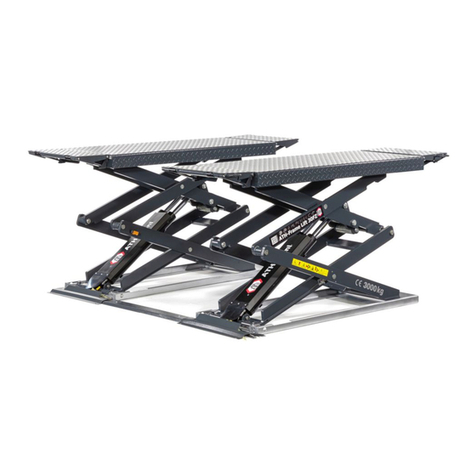
WERTHER INTERNATIONAL RPK25/B Instructions for use

I
GB
F
D
E
Sollevatore elettroidraulico a forbice
Electroydraulic scissor car lift
Pont élévateur électro-hydraulique à ciseaux
Elektroidraulische Scherenhebühne
Rampa tipo tijera electro-hidraulico para autos
RPK25/B
Werther 1-52,66-77 APAC 53-55,4-52,66-76,79 OMA 61-63,4-52,66-76,78
Italgarage 57-59,4-52,66-76,80
L/14


Manuale di istruzioni per l’uso e la manutenzione del
Instructions and maintenance manual for
Manuel d’instructions pour l’utilisation et l’entretien du:
Bedienungs- und Wartungsanleitung für
Manual de instrucciones para uso y mantenimiento de los
Sollevatore elettroidraulico a forbice
Electroydraulic scissor car lift
Pont élévateur électro-hydraulique à ciseaux
Elektroidraulische Scherenhebühne
Rampa tipo tijera electro-hidraulico para autos
Modello - Model - Modèle - Modell - Modelos
RPK25/B
COSTRUTTORE: - MANUFACTURER: - CONSTRUCTEUR: - HERSTELLER: - FABRICANTE:
WERTHER INTERNATIONAL S.p.A.
Via F. BRUNELLESCHI, 12
42124 CADE’ (RE) - ITALY
Telefono ++ / +522 / 9431 (r.a.) - Telefax ++ / +522 / 941997
1aEmissione - 26 Maggio 2008 - 1st Edition - 26 May 2008
1aÉdition - 26 Mai 2008 - 1. Ausgabe - 26 Mai 2008 - 1ª Edición – 26 Mayo 2008
CENTRO DI ASSISTENZA AUTORIZZATO:
AUTHORISED SERVICE CENTRE:
SERVICE APRÈS-VENTE AGRÉÉ:
KUNDENDIENSTCENTER
CENTRO DE ASISTENCIA AUTORIZADO:
Rev.8 ..........................................17/12/2014
1

INDICE
Cap.1 INTRODUZIONE 4
Cap.2 DESCRIZIONE GENERALE 8
Cap.3 DESCRIZIONE TECNICA DEL 15
SOLLEVATORE
Cap.4 INSTALLAZIONE DELSOLLEVATORE 23
Cap.5 ISTRUZIONI PER L'USO 31
Cap.6 DISPOSIZIONI INERENTI LA SICUREZZA 39
Cap.7 INTERVENTI DI MANUTENZIONE 43
Appendice A Informazioni 49
Appendice B Parti di ricambio 49
INDEX
Chapter 1 INTRODUCTION 4
Chapter 2 GENERAL DESCRIPTION 8
Chapter 3 TECHNICAL DESCRIPTION 15
OF THE LIFT
Chapter 4 INSTALLING THE LIFT 23
Chapter 5 INSTRUCTIONS FOR USE 31
Chapter 6 SAFETY REGULATIONS 39
Chapter 7 MAINTENANCE WORK 43
Appendix A Special notes 49
Appendix B Spare parts 49
2

TABLE DES MATIÈRES
Chap. 1 INTRODUCTION 5
Chap. 2 DESCRIPTION GÉNÉRALE 8
Chap. 3 DESCRIPTION TECHNIQUE 16
DE L'ÉLÉVATEUR
Chap. 4 INSTALLATION DE L'ÉLÉVATEUR 24
Chap. 5 INSTRUCTIONS D'UTILISATION 32
Chap. 6 CONSIGNES DE SÉCURITÉ 40
Chap. 7 INTERVENTIONS D'ENTRETIEN 44
Annexe A Informations 50
Annexe B Pièces détachées 50
INHALT
Kap. 1 EINFÜHRUNG 5
Kap. 2 ALLGEMEINE BESCHREIBUNG 8
Kap. 3 TECHNISCHE BESCHREIBUNG 16
DER HEBEBÜHNE
Kap. 4 INSTALLATION DER HEBEBÜHNE 24
Kap .5 BENUTZUNGSANWEISUNGEN 32
Kap. 6 SICHERHEITSBESTIMMUNGEN 40
Kap. 7 WARTUNGSARBEITEN 44
Anhang A Informationen 50
Anhang B Ersatzteile 50
ÍNDICE
Cap.1 INTRODUCCIÓN 5
Cap.2 DESCRIPCIÓN GENERAL 5
Cap.3 DESCRIPCIÓN TÉCNICA 16
DEL ELEVADOR
Cap.4 INSTALACIÓN DEL ELEVADOR 24
Cap.5 INSTRUCCIONES DE USO 32
Cap.6 DISPOSICIONES RELATIVAS 40
A LA SEGURIDAD
Cap.7 OPERACIONES DE MANTENIMIENTO 44
Apéndice A Información 50
Apéndice B Piezas de repuesto 50
3

CAP.1 INTRODUZIONE
IATTENZIONE
Questo manuale è stato scritto per il personale di officina addetto
all’uso del sollevatore (operatore) e per il tecnico addetto alla ma-
nutenzione ordinaria (manutentore) pertanto, prima di effettuare
qualsiasi operazione sul sollevatore e/o sul suo imballaggio, oc-
corre leggere attentamente tutto il manuale, poichè esso contiene
informazioni importanti per:
- LA SICUREZZA DELLE PERSONE addette all’uso ed alla manu-
tenzione ordinaria,
- LA SICUREZZA DEL SOLLEVATORE,
- LA SICUREZZA DEI VEICOLI sollevati.
CONSERVAZIONE DEL MANUALE
Il manuale è parte integrante del sollevatore e deve sempre accompa-
gnarlo, anche in caso di vendita.
Esso deve sempre essere conservato in vicinanza del sollevatore, in lu-
ogo facilmente accessibile.
L’operatore ed il manutentore devono poterlo reperire e consultare rapi-
damente in qualsiasi momento.
SI RACCOMANDA, IN PARTICOLARE, UNA LETTURA ATTENTA E
RIPETUTA DEL CAPITOLO 3, CHE CONTIENE IMPORTANTI
INFORMAZIONI E AVVISI RELATIVI ALLA SICUREZZA.
Il sollevatore è stato progettato e costruito rispettando quanto segue:
LEGGI:
Direttive Europee
2004/108/CE - 2006/42/CE - 2006/95/CE
NORME TECNICHE :
Norme Europee
EN 1493-2010 / EN ISO 12100/1 2005 - EN ISO 12100/2 2005
IMPIANTO ELETTRICO
EN 60204-1
CHAPTER 1 INTRODUCTION
IWARNING
This manual has been prepared for workshop personnel expert in
the use of the lift (operator) and technicians responsible for routi-
ne maintenance (maintenance fitter); read the manual before car-
rying out any operation with the lift and/or the packing. This ma-
nual contains important information regarding:
- THE PERSONAL SAFETY of operators and maintenance workers,
- LIFT SAFETY,
- THE SAFETY OF LIFTED VEHICLESù
CONSERVING THE MANUAL
The manual is an integral part of the lift , which it should always accom-
pany , even if the unit is sold.
The manual must be kept in the vicinity of the lift, in an easily accessi-
ble place.
The operator and maintenance staff must be able to locate and consult
the manual quickly and at any time.
ATTENTIVE AND REPEATED READING OF CHAPTER 3 , WHICH
CONTAINS IMPORTANT INFORMATION AND SAFETY WARNINGS,
IS PARTICULARLY RECOMMENDED.
Lift rack has been designed and built in compliance with the following:
LAWS
European directives
2004/108/CE - 2006/42/CE - 2006/95/CE
TECHNICAL STANDARDS
European standards
EN 1493-2010 / EN ISO 12100/1 2005 - EN ISO 12100/2 2005
ELECTRIC PLANT
EN 60204-1
4

CHAP.1 INTRODUCTION
IATTENTION
Ce manuel a été rédigé pour le personnel d’atelier affecté à l’utili-
sation du pont élévateur (opérateur) et au technicien chargé de la
maintenance ordinaire (agent d’entretien). Avant d’effectuer quel-
que opération que ce soit sur l’élévateur et/ou sur l’emballage, il
est impératif de lire attentivement l’ensemble de ce manuel car ce-
lui-ci contient des informations importantes pour:
- LA SECURITE DES PERSONNES chargées de l’utilisation et de la
maintenance ordinaire,
- LA SECURITE DE L’ELEVATEUR,
- LA SECURITE DES VEHICULES soulevés.
CONSERVATION DU MANUEL
Ce manuel fait intégralement partie de l’élévateur et doit toujours l’ac-
compagner, même en cas de revente.
Il doit toujours être conservé à proximité de l’élévateur, en un endroit fa-
cilement accessible.
L’opérateur et l’agent d’entretien devront pouvoir s’y référer et le con-
sulter rapidement à tout moment.
IL EST EN PARTICULIER RECOMMANDE DE PROCEDER A UNE
LECTURE ATTENTIVE ET REPETEE DU CHAPITRE 3 QUI CONTIENT
DES INFORMATIONS IMPORTANTES ET DES CONSIGNES RELATIVES
A LA SECURITE.
L’élévateur a été conçu et construit en conformité avec les réglementations
suivantes:
LOIS
Directives européennes
2004/108/CE - 2006/42/CE - 2006/95/CE
NORMES TECHNIQUES
Norme européenne
EN 1493-2010 / EN ISO 12100/1 2005 - EN ISO 12100/2 2005
ÉQUIPEMENT ÉLECTRIQUE
EN 60204-1
KAP.1 EINLEITUNG
IACHTUNG
Dieses Handbuch wurde für das mit der Bedienung der Hebebühne
beauftragte Werkstattpersonal (Bediener) und für den mit der or-
dentlichen Wartung beauftragten Techniker (Wartungsfachmann)
verfasst. Daher ist vor jedem Eingriff an der Hebebühne und/oder
an dem Verpackungsmaterial aufmerksam dieses Handbuch zu le-
sen, denn es enthält wichtige Informationen für:
- Die Sicherheit der mit der dem Gebrauch und der ordentlichen War-
tung beauftragten Personen
- Die Sicherheit der Hebebühne
- Die Sicherheit des zu hebenden Fahrzeuges
AUFBEWAHRUNG DES HANDBUCHES
Das Handbuch stellt ein Teil der Hebebühne dar und muss diese immer
begleiten, auch wenn sie verkauft wird
Das Handbuch muss immer an einem leicht zugänglichen Ort in der Nähe
der Hebebühne aufbewahrt werden.
Der Bediener und die mit der Wartung beauftragte Person müssen das Han-
dbuch jederzeit zur Verfügung haben.
INSBESONDERE WIRD EMPFOHLEN, DAS KAPITEL 3 MEHRMALS
AUFMERKSAM ZU LESEN, DENN DIESES KAPITEL ENTHÄLT
WICHTIGE INFORMATIONEN UND HINWEISE BEZÜGLICH DER
SICHERHEIT.
Die Hebebühnen werden unter Beachtung der folgenden Vorschriften en-
twickelt und hergestellt:
GESETZE
Europäische Richtlinien
2004/108/CE - 2006/42/CE - 2006/95/CE
TECHNISCHER STANDARD
Europäischer Standard
EN 1493-2010 / EN ISO 12100/1 2005 - EN ISO 12100/2 2005
Elektrik
EN 60204-1
CAP.1 INTRODUCCIÓN
IATENCIÓN
Este manual ha sido escrito para el personal de taller que se ocu-
pa del uso del elevador (operario) y para el técnico que se ocupa
del mantenimiento ordinario (servicio) por tanto, antes de realizar
cualquier operación en el elevador y/o en su embalaje, es preciso
leer atentamente todo el manual, ya que contiene informaciones
importantes para:
- LA SEGURIDAD DE LAS PERSONAS que se ocupan del uso y del
mantenimiento ordinarios
- LA SEGURIDAD DEL ELEVADOR,
- LA SEGURIDAD DE LOS VEHÍCULOS elevados.
CONSERVACIÓN DEL MANUAL
El manual es parte integrante del elevador y debe acompañarlo siem-
pre, aun en caso de venta.
Deberá estar cerca del elevador, en lugar fácilmente accesible.
El operario y el personal de servicio lo deberá hallar rápidamente para
consultar en cualquier momento.
SE RECOMIENDA, PARTICULARMENTE, UNA LECTURA ATENTA Y
REPETIDA DEL CAPÍTULO 3, QUE CONTIENE IMPORTANTES
INFORMACIONES Y AVISOS RELATIVOS A LA SEGURIDAD.
Los elevadores han sido proyectados y fabricados respectando las si-
guientes:
LEYES
Directivas europeas
2004/108/CE - 2006/42/CE - 2006/95/CE
NORMAS TÉCNICAS
Normas europeas
EN 1493-2010 / EN ISO 12100/1 2005 - EN ISO 12100/2 2005
EQUIPO ELÉCTRICO:
EN 60204-1
5

Il sollevamento, il trasporto, il disimballo, il montaggio, l’installazione e la
messa in servizio, la taratura e le registrazioni iniziali, la manutenzione
STRAORDINARIA, la riparazione, la revisione, lo spostamento e lo sman-
tellamento del sollevatore devono essere eseguiti dai tecnici specializzati
dei RIVENDITORI AUTORIZZATI o dei CENTRI ASSISTENZA
AUTORIZZATI dal Costruttore (vedere centro assistenza autorizzato
indicato nel frontespizio):
Il costruttore non risponde di alcun danno a persone, veicoli od oggetti ca-
usati dagli interventi sopracitati se effettuati da personale non autorizzato
o da un uso improprio o non consentito del sollevatore
Per tutte queste attività vengono indicati, nel presente manuale, soltanto
gli aspetti (operativi e di sicurezza) che possono essere utili anche all’ope-
ratore ed al manutentore per comprendere meglio la struttura ed il funzio-
namento del sollevatore e per un suo migliore utilizzo.
Per comprendere il linguaggio adottato nel presente manuale, l’operatore
deve possedere esperienza specifica nelle attività di officina, di assisten-
za, manutenzione e riparazione dei veicoli nonchè la capacità di interpre-
tare correttamente i disegni e le descrizioni riportate nel manuale e la co-
noscenza delle norme antinfortunistiche generali e specifiche vigenti nel
paese in cui viene installato il sollevatore.
Gli stessi criteri valgono per la scelta del tecnico manutentore che dovrà,
inoltre, possedere le conoscenze tecniche specifiche e specialistiche
(meccaniche, elettriche) necessarie per effettuare in sicurezza gli
interventi previsti nel manuale.
Nel testo del manuale troverete spesso le diciture “operatore” e “manuten-
tore” il cui significato è il seguente:
OPERATORE: persona addetta all’uso del sollevatore.
MANUTENTORE: persona addetta alla manutenzione ordinaria del solle-
vatore.
The lifting, transport, unpacking, assembly, installation, starting up,
initial adjustment and testing, EXTRAORDINARY maintenance, re-
pair, overhauls, transport and dismantling of the lift must be perfor-
med by specialised personnel from the LICENSED DEALER or an
SERVICE CENTRE authorised by the manufacturer (see authorised
dealer on frontispiece).
The manufacturer declines all responsibility for injury to persons or
damage to vehicles or objects when any of the above mentioned
operations has been performed by unauthorised personnel or when
the rack has been subject to improper use.
This manual indicates only the operative and safety aspects that may
prove useful to the operator and maintenance worker, in better un-
derstanding the structure and operation of the lift and for best use of
the same.
In order to understand the terminology used in this manual, the ope-
rator must have specific experience in workshop, service, maintenan-
ce and repair activities, the ability to interpret correctly the drawings
and descriptions contained in the manual and be acquainted with the
general and specific safety rules relevant to the country in which the
machine has been installed.
The same applies to the maintenance fitter, who must also possess
specific and specialised knowledge (mechanical, engineering) nee-
ded to perform the operations described in the manual in complete
safety.
The words “operator” and “maintenance fitter” used in this manual
are construed as follows:
OPERATOR: person authorised to use the lift
MAINTENANCE FITTER: person authorised for routine maintenance
of the lift.
6

Le soulèvement, le transport, le déballage, le montage, l’installation et
la mise en service, le tarage ou les réglages initiaux, l’entretien
EXTRAORDINAIRE, la réparation, la révision, le déplacement et la de-
struction de l’élévateur doivent être effectués par les techniciens spé-
cialisés des REVENDEURS AUTORISES et des CENTRES DE
SERVICE APRES-VENTE AGREES par le Constructeur (voir en pre-
mière page l’adresse du service après-vente agréé).
Le constructeur dégage toute responsabilité vis à vis des dommages qui po-
urraient être causés aux personnes, aux véhicules ou autres objets lors des
interventions citées ci-dessus si celles-ci ont été effectuées par un personnel
non autorisé, ou lors d’une utilisation de l’élévateur incorrecte ou non prévue
par le constructeur.
Pour toutes ces opérations, ne sont indiqués dans ce manuel que les
aspects (opérationnels et de sécurité) qui peuvent être utiles à l’opérateur et
à l’agent d’entretien pour mieux comprendre la structure et le fonctionnement
de l’élévateur dans le but d’en améliorer l’utilisation.
Pour comprendre le langage adopté dans le présent manuel, l’opérateur doit
posséder une expérience spécifique dans le domaine du travail en atelier, du
service après vente, de l’entretien et de la réparation automobile, ainsi que la
capacité d’interpréter correctement les dessins et les descriptions figurant
dans ce manuel et la connaissance des normes générales relatives à la pro-
tection contre les accidents du travail en vigueur dans le pays où l’élévateur
est installé.
Les mêmes critères sont à prendre en compte pour le choix de l’agent d’en-
tretien qui devra, en plus, posséder les connaissances spécifiques et techni-
ques (mécaniques, électriques) nécessaires pour effectuer en toute sécurité
les interventions prévues dans ce manuel.
Dans les textes de ce manuel, vous trouverez souvent les termes “opé-
rateur” et “agent d’entretien” dont la signification est la suivante:
OPERATEUR : personne affectée à l’utilisation de l’élévate-
ur,AGENT D’ENTRETIEN : personne chargée de l’entretien ordinai-
re de l’élévateur.
Heben, Transport, Auspacken, Montage, Installation und Inbetriebnah-
me, Eichung und Einstellungen, AUSSERORDENTLICHE Wartung,
Reparatur, Inspektion, Verschiebung und Abbruch der Hebebühne
müssen durch Fachtechniker der vom Hersteller AUTORISIERTEN
VERTRAGSHÄNDLER oder AUTORISIERTEN
KUNDENDIENSTCENTER (siehe auf der Titelseite angegebenes au-
torisiertes Kundendienstcenter) durchgeführt werden:
Der Hersteller haftet nicht für Personen- und/oder Sachschäden, die auf die
oben beschriebenen Eingriffe zurückgeführt werden können, wenn diese
Eingriffe durch nicht autorisiertes Personal durchgeführt wurden, oder wenn
die Schäden auf einen unsachgemäßen oder unzulässigen Gebrauch der
Hebebühne zurückzuführen sind.
Für alle diese Tätigkeiten werden im vorliegenden Handbuch nur die Aspek-
te (bezüglich Betrieb und Sicherheit) berücksichtigt, die auch dem Bediener
oder dem Wartungsfachmann für ein besseres Verstehen der Struktur und
des Betriebs der Hebebühne sowie für einen besseren Gebrauch derselben
nützlich sein können.
Zum Verstehen der in diesem Handbuch angewandten Fachsprache muss
der Bediener über spezifische Werkstatterfahrungen bezüglich Pannen-
dienst sowie Wartung und Reparatur von Fahrzeugen verfügen, und muss
in der Lage sein, die in diesem Handbuch enthaltenen Zeichnungen und
Beschreibungen zu verstehen. Ferner muss der Bediener die im jeweiligen
Aufstellland der Hebebühne geltenden allgemeinen und spezifischen Unfal-
lverhütungsvorschriften kennen.
Die gleichen Kriterien gelten für die Wahl des Wartungstechnikers, der ferner
über die spezifischen technischen und Fachkenntnisse (Mechanik, Elektrik)
verfügen muss, die zur Ausführung der im Handbuch beschriebenen Arbe-
itsgänge unter sicheren Bedingungen erforderlich sind.
Im Handbuch werden häufig die Begriffe “Bediener” und “Wartungsfac-
hmann” verwendet. Diese Begriffe haben folgende Bedeutung:
BEDIENER: Für den Betrieb der Hebebühne zuständige Person.
WARTUNGSFACHMANN: Für die ordentliche Wartung der Hebe-
bühne zuständige Person.
La elevación, el transporte, el desembalaje, el montaje, la instalaci-
ón y puesta en funcionamiento, la verificación y los ajustes inicia-
les, el mantenimiento EXTRAORDINARIO, la reparación, la revisi-
ón, la manipulación y el desmantelamiento del elevador deben ser
ejecutados por los técnicos especializados del REVENDEDOR
AUTORIZADO o por los CENTROS DE ASISTENCIA AUTORIZADOS
del Fabricante (ver centro de asistencia autorizado indicado al
principio).
El fabricante no responde de daños a personas, vehículos u objetos ca-
usados por las intervenciones antes citadas si se han efectuado por
personal no autorizado o por un uso impropio o no consentido del ele-
vador.
Para todas estas actividades se indican en el presente manual, sola-
mente los aspectos operativos y de seguridad que pueden ser útiles al
usuario y al encargado del mantenimiento para comprender perfecta-
mente la estructura y el funcionamiento del elevador y para utilizarlo
correctamente.
Para comprender el lenguaje usado en este manual, el operario debe
tener experiencia específica en las actividades de taller, de asistencia,
mantenimiento y reparación de vehículos así como la capacidad de in-
terpretar correctamente los dibujos y descripciones indicades en el ma-
nual y el conocimiento de las normas preventivas generales y específi-
cas vigentes en el país donde se instala el elevador.
Idénticos criterios son válidos para la elección del técnico de manteni-
miento que deberá, además, poseer los conocimientos específicos y de
especialización (mecánico, eléctrico) necesarios para realizar con se-
guridad las intervenciones previstas en el manual.
En el texto del manual se encontrará a menudo las frases “operario” y
“personal de servicio” cuyos significados son los siguientes:
OPERARIO: persona que se ocupa del uso del elevador.
PERSONAL DE SERVICIO: persona que se ocupa del manteni-
miento ordinario del elevador.
7

Fig. 1
CHAP. 2 DESCRIPTION GÉNÉRALE
2.1 Dimensions hors tout de l’élévateur
Les dimensions hors tout de l’élévateur sont indiquées sur la figure 1
ci-dessous.
! NOTE !
Sur tout le périmètre de l’élévateur, il est nécessaire
de garantir un dégagement d’au moins 50 cm.
CAP.2 DESCRIZIONE GENERALE
2.1 Ingombri del sollevatore
Le dimensioni di ingombro del sollevatore sono illustrate nella fig. 1, di
seguito riportata.
! NOTA !
Lungo tutto il perimetro del sollevatore deve essere
garantito uno spazio di almeno 50 cm.
KAP. 2 ALLGEMEINE BESCHREIBUNG
2.1Abmessungen der Hebebühne
Die Abmessungen der Hebebühne werden auf der folgenden Abb. 1
wiedergegeben.
! HINWEIS !
Um die gesamte Hebebühne herum muss ein Freira-
um von zumindest 50 cm garantiert werden.
CHAPTER 2 GENERAL DESCRIPTION
2.1 Lift dimensions
The overall dimensions of the lift are illustrated in Fig. 1 below.
! NOTE !
There must a clearance of at least 50 cm all around
the perimeter of the lift
CAP.2 DESCRIPCIÓN GENERAL
2.1 Dimensiones externas del elevador
Las dimensiones externas del elevador se ilustran en la fig. 1, presen-
tada a continuación.
¡NOTA!
A lo largo de todo el perímetro del elevador debe
estar garantizado un espacio libre de por lo menos
50 cm
8

Fig.2
2.2 Utilizzatore appropriato
La semplicità di funzionamento del sollevatore non richiede qualifica
supplementare rispetto a quanto riportato nel capitolo 1, paragrafo 1.2.
La lettura del presente manuale si ritiene sufficiente a garantire una
preparazione che assicuri di poter correttamente operare con il solleva-
tore stesso. Si dovrà curare in particolare gli aspetti inerenti la Sicurez-
za per l’Uomo e per 1’Ambiente. Gli interventi di regolazione o manu-
tenzione dovranno essere eseguiti da operatori preventivamente qualifi-
cati secondo quanto prescritto al capitolo 1, paragrafo 1.2.
2.3 Fornitura
Di seguito vengono elencate tutte le parti di cui si compone il sollevatore e
che vengono fornite al Cliente:
·sollevatore;
·centralina di comando comprensiva di pulsantiera mobile;
·braccio di tiro, composto dalle seguenti parti:
·staffa di supporto orizzontate con piastra per il fissaggio;
·braccio verticale;
·n° 3 ruote rimovibili, per la movimentazione a terra del braccio completo;
·catena di tiro con morsetto per fissaggio al braccio, gancio e cavo di sicu-
rezza;
·n° 1 cilindro ad azionamento pneumatico con forcella.
·n° 4 staffe di supporto per sostegno autovettura;
·n° 4 piattelli gommati
·n° 4 morse per aggancio vettura;
·n°4 cavalletti
·n° 4 tasselli a espansione per il fissaggio a terra del basamento.
Oltre alle parti suddette, a richiesta del cliente, può essere fornito anche il se-
guente accessorio (optional):
·pompa pneumatica (fig. 2) per 1’azionamento del braccio di tiro.
La trattazione di tutte le parti sopra elencate ed il loro funzionamento è
riportata nel capitolo 3 del presente manuale.
2.2 Appropriate user
The simplicity of use of the lift requires no additional qualification to
what is specified in Chapter 1, paragraph 1.2. Reading this manual is
deemed sufficient to guarantee a preparation that ensures the lift can
be operated correctly. The safety aspects must be observed in particu-
lar for both man and environment. All adjustments and maintenance
work must be carried out by operators who are already qualified accor-
ding to what is prescribed in Chapter 1, paragraph 1.2.
2.3 Supply
Below is a list of all the parts that make up the lift and which are sup-
plied to the customer:
·lift;
·control unit including the mobile push button panel;
·pulling arm consisting of the following parts:
·horizontal support bracket with fixing plate;
·vertical arm;
·no.3 removable wheels for moving the arm assembly along the ground;
·pulling chain with clamp for fixing to the arm, hook and safety cable;
·no. 1 pneumatically operated cylinder with fork.
·no. 4 brackets to support the vehicle;
·no. 4 rubberised plates
·no. 4 vices for gripping the vehicle;
·no. 4 stands
·no. 4 expansion bolts for anchoring the base to the floor.
Besides the aforementioned parts, the following accessory may also be
requested by the customer (optional feature):
·pneumatic pump (Fig. 2) for operating the pulling arm.
All the aforementioned parts and their operation are explained in Chap-
ter 3 of this manual.
9

2.2 Utilisateur
Compte tenu de la simplicité de son fonctionnement, l'élévateur ne né-
cessite aucune compétence particulière outre celles indiquées au cha-
pitre 1, paragraphe 1.2. La lecture du présent manuel est suffisante
pour garantir une préparation permettant d'utiliser correctement l'éléva-
teur. Il est important d'accorder tout le soin nécessaire aux aspects re-
latifs à la Sécurité des Personnes et de l'Environnement. Les interven-
tions de réglage ou d'entretien doivent être confiées à des opérateurs
qualifiés (à cet effet, se reporter au contenu du chapitre 1, paragraphe
1.2).
2.3 Fourniture
Ci-après sont indiquées toutes les parties dont l'élévateur fourni au
client est constitué :
·"élévateur ;
·"groupe de commande avec pupitre mobile ;
·"bras de traction constitué des éléments suivants :
·"bride de soutien horizontal avec plaque de fixation ;
·"bras vertical ;
·"3 roues amovibles, pour le déplacement à terre du bras complet ;
·"chaîne de traction avec pince de fixation au bras, crochet et câble
de sécurité ;
·"1 vérin à actionnement pneumatique avec étrier ;
·"4 brides de soutien du véhicule ;
·"4 protections caoutchoutées ;
·"4 pinces de fixation du véhicule ;
·"4 chevalets ;
·"4 chevilles à expansion de fixation au sol de la base.
·Outre les parties ci-dessus, l'accessoire suivant peut être fourni en
option, à la demande du client :
·"pompe pneumatique (fig. 2) d'actionnement du bras de traction ;
·La description détaillée de toutes les parties ci-dessus et leur fon-
ctionnement figurent dans le chapitre 3 du présent manuel.
2 Anforderungen an den Bediener
Aufgrund der einfachen Funktionsweise der Hebebühne macht sie ge-
genüber den Angaben in Kapitel 1, Abschnitt 1.2 keine weiteren Qualifi-
kationen erforderlich. Die Lektüre des vorliegenden Handbuches ist au-
sreichend, um eine Vorbereitung zu garantieren, die eine or-
dnungsgemäße Benutzung der Hebebühne sicherstellt. Die Aspekte
der Sicherheit von Mensch und Umwelt müssen in besonderer Weise
beachtet werden. Die Eingriffe zur Einstellung oder Wartung müssen
von Bedienern ausgeführt werden, die die in Kapitel 1, Abschnitt 1.2
angegebene Qualifikation aufweisen.
2.3 Lieferung
Im Folgenden werden alle Bauteile aufgeführt, aus denen sich die He-
bebühne zusammensetzt und die dem Kunden geliefert werden:
·Hebebühne;
·Steuereinheit einschließlich mobiler Bedieneinheit;
·Zugarm, bestehend aus den folgenden Bauteilen:
·horizontaler Halterungsbügel mit Platte für die Befestigung;
·vertikaler Arm;
·3 abnehmbare Räder für die Bewegung des vollständigen Arms am
Boden;
·Zugkette mit Klemme für die Befestigung am Arm, Haken und Sicher-
heitskabel;
·1 pneumatisch betätigter Zylinder mit Gabel
·4 Halterungsbügel zur Abstützung des Fahrzeugs;
·4 gummierte Tellerchen
·4 Klemme für die Fixierung des Fahrzeugs;
·4 Böcke
·4 Expansionsdübel für die Befestigung des Unterbaus am Boden.
·Außer den vorgenannten Bauteilen kann auf Anfrage des Kunden
auch die folgende Zubehörvorrichtung geliefert werden:
·Druckluftpumpe (Abb. 2) für die Betätigung des Zugarms.
·In Kapitel 3 des vorliegenden Handbuches wird die Funktionsweise
aller vorgenannten Bauteile beschrieben.
2 Usuario apropiado
La sencillez de funcionamiento del elevador no requiere cualificaciones
suplementarias respecto a cuanto indicado en el capítulo 1, párrafo 1.2.
La lectura del presente manual se considera suficiente para garantizar
una preparación que asegure poder utilizar correctamente el propio ele-
vador. En particular se deberá prestar especial atención a los aspectos
relacionados con la seguridad para la persona y para el medio ambien-
te. Las operaciones de ajuste o mantenimiento deberán ser efectuadas
por operadores previamente cualificados según cuanto prescrito en el
capítulo 1, párrafo 1.2.
2.3 Suministro
A continuación se indican todas las partes que componen el elevador y
que son entregadas al Cliente:
·elevador;
·centralita de mando que incluye la botonera móvil;
·brazo de tiro, formado por las siguientes partes:
·soporte horizontal con placa para la fijación;
·brazo vertical;
·n° 3 ruedas desmontables, para el desplazamiento en el suelo del
brazo completo;
·cadena de tiro con abrazadera para la fijación al brazo, gancho y ca-
ble de seguridad;
·n° 1 cilindro con accionamiento neumático con horquilla;
·n° 4 soportes para sostener el automóvil;
·n° 4 platillos engomados;
·n° 4 morsas para enganchar el automóvil;
·n°4 caballetes;
·n° 4 pernos de expansión para fijar al suelo la base.
·Además de dichas partes, a petición del cliente, se puede suministrar
también el siguiente accesorio (opcional):
·bomba neumática (fig. 2) para e1 accionamiento del brazo de tiro.
·La descripción de todas las partes susodichas y su funcionamiento
se presentan en el capítulo 3 del presente manual.
10

2.4 Identificazione delle varie versioni
Il sollevatore è prodotto in varie versioni che si differenziano sostan-
zialmente solo dal tipo di alimentazione elettrica, alla quale deve essere
collegato, mentre rimangono identiche le caratteristiche meccaniche.
Le varie versioni sono identificate dal Costruttore con le seguenti sigle:
-G750/3: 230 V-50/60Hz monofase;
-G750 230/400 V - 50 Hz trifase;
2.5 Potenzialità e limitazioni d’uso del sollevatore
nPortata max: .....................................................................3000 kg
nSerbatoio olio: ..................................................................... .....7 l
nPressione max. idraulica (con 2500 kg di carico):..............275 bar.
nPressione idraulica in esercizio:..........................................210 bar.
nAlimentazione elettrica:...........................................a seconda
della versione (vedere paragrafo 2,4).
nAssorbimento elettrico:.........................................................3 kW.
nAlimentazione pneumatica:..................................................6÷8 bar.
nVelocità max................................................0,05 m/sec (in discesa).
nCorsa massima in altezza:.................................................1100 mm.
nDimensioni sollevatore:
nlunghezza:..........................................................................2800 mm
nlunghezza max con braccio di tiro:.................. ................4000 mm
nlarghezza:.............................................................................. 882 mm
nlarghezza max con staffe di supporto:................................1772 mm;
naltezza massima sollevatore ............................................1100 mm
nAltezza massima con braccio di tiro:......................... .......2600 mm.
nDimensioni braccio
naltezza (con ruote):.............................................................1.800 mm;
nlunghezza:..........................................................................1400 mm.
nlarghezza: ........................................................................... 350 mm;
nDimensioni centralina di comando:
nlunghezza:..............................................................................650 mm;
nlarghezza:..............................................................................450mm.
naltezza:...................................................................................220 mm
nPeso sollevatore con accessori ........................... ....................400 kg
nPeso centralina di comando.......................................................50 kg
2.4 Identification of the various versions
The lift is made in various versions differing basically only by the type of
electrical power to which it is connected while the mechanical characte-
ristics are the same.
The various versions are identified by the Manufacturer with the follo-
wing codes:
-G750/3: 230 V-50/60Hz single-phase;
-G750: 230/400 V - 50 Hz three-phase
2.5 Potential and limitations of lift use
nMax. Capacity: .................................................................. 3000kg
nOil tank:.....................................................................................7l
nMax. hydraulic pressure (with a 2,500 kg load):........275 bar
nHydraulic pressure when working:..........................................210bar
nElectrical power:.......................................Depending on the version
(see paragraph 2,4).
nElectrical absorption:...............................................................3 kW
nPneumatic power:...................................................................6÷8 bar
nMax. speed ....................................................0,05 m/sec (in descent).
nMaximum travel in height:......................................................1100mm
nLift dimensions:
nlength................................................................................. 2800 mm
nmax. length with pulling arm:..................................................4000 mm
nwidth:.................................................................................... 882 mm
nmax. width with supporting brackets:.....................................1772 mm
nmaximum lift height ...............................................................1100 mm
nMaximum height with pulling arm:.........................................2600 mm
nArm dimensions:
nheight (with wheels):.............................................................1800 mm
nlength:....................................................................................1400 mm
nwidth:.......................................................................................350 mm
nControl unit dimensions:
nlength:......................................................................................650 mm
nwidth:........................................................................................450 mm
nheight:......................................................................................220 mm
nLift weight with accessories ................................ ....................400 kg
nControl unit weight ...................................................................50 kg
11

2.4 Identification des différentes versions
L'élévateur est réalisé dans différentes versions dont la principale diffé-
rence concerne le type d'alimentation électrique auquel le pont doit être
branché. Les caractéristiques mécaniques sont quant à elle identiques.
Le Constructeur identifie les différentes versions avec les sigles sui-
vants :
- G750/3: 230 V-50/60Hz monophasé ;
- G750 : 230/400 V - 50 Hz triphasé ;
2.5 Potentiel et limites d'utilisation de l'élévateur
nPortée max. : ......................................................................3000 kg
nRéservoir d'huile :.............................................................. ......7 ll
nPression max. hydraulique(avec charge de 2500 kg) : ...... 275 bar
nPression hydraulique de service : ....................................... 210 bar
nAlimentation électrique : ...................................................................
en fonction de la version (voir chapitre 2.4)
nAbsorption électrique : ......................................................... 3 kW
nAlimentation pneumatique : ................................................. 6÷8 bar
nVitesse max. : .......................................... 0,05 m/sec (en descente)
nCourse maximum en hauteur : .......................................... 1100 mm
nDimensions élévateur :
nLongueur : ......................................................................... 2800 mm
nLongueur max. avec bras de traction :.............................. 4000 mm
nLargeur : .............................................................................. 882 mm
nLargeur max. avec brides de soutien : .............................. 1772 mm
nHauteur maximum élévateur : ...........................................1100 mm
nHauteur maximum avec bras de traction : ........................ 2600 mm
nDimensions bras
nHauteur (roues comprises) : ...............................................1800 mm
nLongueur : ..........................................................................1400 mm
nLargeur : ...............................................................................350 mm
nDimensions unité de commande :
nLongueur : ............................................................................650 mm
nLargeur :................................................................................ 450mm
nHauteur : ..............................................................................220 mm
nPoids élévateur avec accessoires :...................................... 400 kg
nPoids unité de commande : ....................................................50 kg
2.4Identifizierung der verschiedenen Versionen
Die Hebebühne wird in verschiedenen Versionen gebaut, die sich vor
allem durch den Typ der Stromversorgung unterscheiden, an die sie an-
geschlossen werden muss, während die mechanischen Eigenschaften
unverändert bleiben.
Die unterschiedlichen Versionen werden vom Hersteller mit den folgen-
den Abkürzungen gekennzeichnet:
-G750/3: 230 V-50/60Hz einphasig;
-G750 230/400 V - 50 Hz dreiphasig;
2.5 Leistungen und Einsatzbeschränkungen der
Hebebühne
nMax. Tragkraft: .................................................................3.000 kg
nÖltank: ..................................................................... …………....7 l
nMax. Hydraulikdruck (mit 2.500 kg Last)..............................275 bar.
nHydraulikdruck beim Betrieb:................................................210 bar.
nStromversorgung:...........................................in Abhängigkeit von der
Version (siehe Abschnitt 2.4).
nStromaufnahme:.................................................................3 kW.
nDruckluftzufuhr:..................................................................6÷8 bar.
nMax. Geschwindigkeit.....................0,05 m/Sek. (bei der Absenkung).
nMax. Hub in der Höhe....................................................1.100 mm.
nAbmessungen der Hebebühne:
nLänge:............................................................................2.800 mm
nMax. Länge mit Zugarm:.................................................4.000 mm
nBreite................................................................................ 882 mm
nMax. Breite mit Halterungsbügeln:...............................1.772 mm;
nMax. Höhe Hebebühne:.................................................1.100 mm
nMax. Höhe mit Zugarm:...............................................2.600 mm.
nAbmessungen Arm
nHöhe (mit Rädern):.........................................................1.800 mm;
nLänge:.............................................................................1.400 mm.
nBreite: ...............................................................................350 mm;
nAbmessungen Steuereinheit:
nLänge:.............................................................................. 650 mm;
nBreite................................................................................220 mm
nGewicht Hebebühne mit Zubehör ....................................400 kg
nGewicht Steuereinheit.........................................................50 kg
2.4 Identificación de las varias versiones
El elevador se puede fabricar en varias versiones que se distinguen bá-
sicamente sólo por el tipo de alimentación eléctrica a la cual se deben
conectar, mientras que no cambian sus características mecánicas.
Las varias versiones están identificadas por el Fabricante con las si-
guientes siglas:
-G750/3: 230 V-50/60Hz monofásica;
-G750 230/400 V - 50 Hz trifásica;
2.5 Potencialidades y limitaciones de uso del elevador
nCapacidad máx. de carga ...............................................3000 kg
nDepósito aceite ......................................................................7 l
nPresión hidráulica máx.
n(con 2500 kg de carga).......................................................275 bar.
nPresión hidráulica en servicio..........................................210 bar.
nAlimentación eléctrica...........................................según la versión
(ver párrafo 2.4).
nConsumo eléctrico.........................................................3 kW.
nAlimentación neumática..................................................6÷8 bar.
nVelocidad máx....................................................0,05 m/s (en bajada).
nCarrera máxima en altura...............................................1100 mm.
nDimensiones del elevador:
nlongitud:..........................................................................2800 mm
nlongitud máx. con brazo de tiro:..................................... 4000 mm
anchura:.............................................................................. 882 mm
nanchura máx. con soportes:............................................1772 mm;
naltura máxima del elevador ..............................................1100 mm
nAltura máxima con brazo de tiro:.....................................2600 mm.
nDimensiones de brazo
altura (con ruedas):..............................................................1800 mm;
nlongitud:.............................................................................1400 mm.
nanchura: ........................................................................... 350 mm;
nDimensiones centralita de control:
nlongitud:..............................................................................650 mm;
nanchura:..............................................................................450mm.
naltura:............................................................................. ......400 kg
nPeso de la centralita de control .............................................50 kg
12

2.6 Tipologia autovetture sollevabili
È previsto il sollevamento di tutte le autovetture presenti in commercio
purché le distanze relative ai pneumatici siano conformi a quanto di se-
guito riportato:
·distanza longitudinale costante: 1250+1750 mm;
·distanza trasversale massima: 4200 mm.
! NOTA !
Le dimensioni suddette sono riferite al centro ruota.
2.7 Modalità di funzionamento
Il sollevatore è concepito per l’azionamento manuale, pertanto richiede
all’operatore solo semplici operazioni riguardo i comandi di salita, disce-
sa e arresto, tramite l’apposita pulsantiera di comando. Non sono previ-
ste, né prevedibili, condizioni di, funzionamento che riducano la sicurez-
za degli addetti all’esecuzione di attività inerenti il sollevatore.
2.8 Disposizioni in materia di sicurezza
Il sollevatore è stato progettato e realizzato in conformità alle disposi-
zioni delle Direttive Europee ad esso applicabili ed in base ai riferimenti
normativi da esse discendenti. Si raccomanda al personale addetto al-
l’esecuzione delle varie attività di operare secondo le modalità prescrit-
te, avendo particolare cura della propria qualifica.
Qualora emergessero situazioni non previste dal presente manuale si
raccomanda di contattare l’Assistenza Tecnica, prima di procedere ulte-
riormente. In caso contrario il Costruttore declinerà ogni responsabilità
derivante da usi scorretti non prevedibili.
Gli argomenti inerenti i dispositivi di sicurezza e le disposizioni in mate-
ria sono diffusamente trattate al1’interno del capitolo 6.
!!! PERICOLO !!!
Il Costruttore raccomanda 1’esecuzione delle singo-
le attività da parte di un. unico addetto, affinché sia-
no evitate condizioni di reciproca esposizione a ri-
schi.
2.6 Types of cars that can be raised
All cars on the market can be raised with this lift provided tyre distances
conform to the following:
·constant longitudinal distance: 1,250+1,750 mm;
·maximum transversal distance: 4,200 mm.
! NOTE !
The above dimensions refer to the wheel centre.
2.7 Operating modes
The lift is designed for manual operation requiring only simple opera-
tions by the operator relating to the ascent, descent and stop controls
using the control push button panel. No operating conditions are forese-
en, or foreseeable, that could reduce the safety of the operator using
the lift.
2.8 Safety regulations
The lift has been designed and made in conformity with the norms of the Eu-
ropean Directives applicable to it and on the basis of the reference standards
pertaining to them. We recommend that the persons carrying out the various
jobs to work the lift do so in accordance with the instructions given, taking
their qualification seriously into consideration.
Should situations arise that are not foreseen in this manual please contact
the Technical Assistance service before going any further otherwise the Ma-
nufacturer declines all responsibility resulting from unforeseeable incorrect
uses.
The points relating to the safety devices and relative instructions are extensi-
vely dealt with in Chapter 6.
!!! DANGER !!!
The Manufacturer recommends that each single ope-
ration be carried out by just the one person so as to
avoid conditions of reciprocal exposure to risks
13

2.6 Types de véhicules soulevables
Le pont est prévu pour soulever tous les véhicules présents dans le
commerce à condition que les distances relatives aux pneumatiques
soient conformes à celles indiquées ci-dessous :
·distance longitudinale constante : 1250+1750 mm
·distance transversale maximum : 4200 mm
! NOTE !
Les dimensions ci-dessus se réfèrent au centre de la
roue.
2.7 Modalités de fonctionnement
L'élévateur est conçu pour être actionné manuellement : aussi son utili-
sation requiert uniquement de la part de l'opérateur les opérations rela-
tives aux commandes de montée, de descente et d'arrêt, par l'intermé-
diaire du pupitre de commande. Aucune des conditions de fonctionne-
ment ne réduit la sécurité des opérateurs durant les opérations
effectuées sur l'élévateur.
2.8 Dispositions en matière de sécurité
L'élévateur a été conçu et réalisé en conformité avec les dispositions
des Directives Européennes applicables et sur la base des standards
qu'elles prescrivent. Il est recommandé de veiller à ce que le personnel
responsable des différentes opérations de travail respecte soigneuse-
ment les modalités prescrites et possède les compétences requises.
Pour toute situation non prévue dans le présent manuel, il est recom-
mandé de prendre contact avec le Service d'Assistance technique
avant de procéder à toute autre opération. Dans le cas contraire, le
Constructeur décline toute responsabilité au regard des conséquences
dérivant d'une utilisation impropre et non prévue.
Les dispositifs et les dispositions de sécurité font l'objet du chapitre 6.
!!! DANGER !!!
Le Constructeur recommande de confier l'utilisation
de l'élévateur à un seul opérateur de façon à éviter
que deux opérateurs ou plus ne s'exposent mutuelle-
ment à des risques.
2.6Hebbare Fahrzeugtypen
Alle handelsüblichen Fahrzeuge können gehoben werden, wenn der
Abstand der Räder den folgenden Angaben entspricht:
·Konstanter Abstand in Längsrichtung: 1250+1750 mm;
·Max. Abstand in Querrichtung: 4.200 mm.
! HINWEIS !
Die vorgenannten Abmessungen beziehen sich auf
das Zentrum des Rads.
2.7Funktionsweise
Die Hebebühne wurde für die Betätigung von Hand konzipiert und da-
her macht sie vom Bediener nur einfache Eingriffe wie Anheben,
Absenken und Anhalten mit der Bedieneinheit erforderlich. Bedingun-
gen, bei denen die Sicherheit der Bediener durch den Betrieb der He-
bebühne beeinträchtigt wird, sind weder vorgesehen noch
vorhersehbar.
2.8Sicherheitsbestimmungen
Die Hebebühne wurde in Übereinstimmung mit den Bestimmungen der
anwendbaren EU-Richtlinien sowie der davon abgeleiteten Referen-
znormen konzipiert und realisiert. Wir empfehlen den Bedienern, unter
Beachtung der vorgeschriebenen Vorgehensweise zu arbeiten und da-
bei in besonderer Weise die eigene Qualifikation zu berücksichtigen.
Bitte wenden Sie sich vor dem Fortfahren an den Kundendienst, falls im
vorliegenden Handbuch nicht vorgesehene Situationen auftreten. Ande-
renfalls lehnt der Hersteller jegliche Haftung für eventuelle Schäden ab,
die auf eine unsachgemäße oder nicht vorhersehbare Benutzung
zurückzuführen sind.
Die Sicherheitsvorrichtungen sowie die Sicherheitsbestimmungen wer-
den in Kapitel 6 abgehandelt.
!!! GEFAHR !!!
Der Hersteller empfiehlt die Durchführung der einzel-
nen Arbeiten durch einen einzigen Arbeiter, um Si-
tuationen mit wechselseitigen Gefahrenaussetzun-
gen zu vermeiden
2.6 Tipología de automóviles elevables
Está prevista la elevación de todos los automóviles en comercio siem-
pre que las distancias relativas a los neumáticos sean conformes a
cuanto indicado a continuación:
·distancia longitudinal constante: 1250+1750 mm;
·distancia transversal máxima: 4.200 mm.
¡NOTA!
Las susodichas medidas se refieren al centro de la
rueda.
2.7 Modalidades de funcionamiento
El elevador está concebido para el accionamiento manual, por lo tanto
requiere al operario solamente unas simples operaciones para los man-
dos de subida, bajada y parada, utilizando la botonera de control previ-
sta. Non están previstas, ni son previsibles, condiciones de funciona-
miento que reduzcan la seguridad de los encargados de actividades
relativas al elevador.
2.8 Disposiciones en materia de seguridad
El elevador ha asido proyectado y fabricado conforme a las disposiciones de
las Directivas Europeas aplicables y sobre la base de las referencias norma-
tivas que de dichas directivas se derivan. Se recomienda al personal encar-
gado de realizar las varias actividades que actúen según las modalidades
prescritas, prestando especial atención a la propia cualificación.
Si surgieran situaciones no previstas en el presente manual se reco-
mienda contactar con el servicio técnico antes de proceder con ulterio-
res operaciones. En caso contrario el Fabricante rehúsa toda responsa-
bilidad derivada de usos erróneos no previsibles.
Los temas relacionados con los dispositivos de seguridad y las disposi-
ciones en materia son presentados detalladamente en el capítulo 6.
¡¡¡ PELIGRO !!!
El Fabricante recomienda que sea un solo operario
quien efectúa las varias actividades, de manera que
se eviten condiciones de recíproca exposición a rie-
sgos.
14

Fig. 3
CAP.3 DESCRIZIONE TECNICA DEL
SOLLEVATORE
3.1 Informazioni generali
Il sollevatore è stato progettato, realizzato e costruito, tenendo in consi-
derazione le esigenze operative degli addetti alle lavorazioni delle la-
miere delle autovetture, all’interno di ambienti di lavoro quali le carroz-
zerie.
Il sollevatore agevola il sollevamento delle autovetture permettendone
la salita senza l’ausilio di pedane.
3.2 Identificazione delle parti
Per quanto concerne la localizzazione delle parti principali che costitui-
scono il sollevatore, esse sono identificate nella fig. 3 {comprensivo di
accessori).
1. Telaio superiore
2. Basamento
3. Bracci di sollevamento
4. Cilindri oleodinamici per sollevamento
5. Staffe di supporto autovettura
6. Morse per aggancio autovettura
7. Staffa orizzontale braccio di tiro
8. Braccio verticale
9. Ruote per movimentazione braccio di tiro
10. Catena con gancio e morsetto di fissaggi
11. Cavo di sicurezza per catena
12. Centralina di comando
13. Pulsantiera di comando
14. Pompa pneumatica per braccio di tiro (optional)
15. Cavalletto
CHAPTER 3 TECHNICAL
DESCRIPTION OF THE LIFT
3.1 General information
The lift has been designed and made taking into consideration the ope-
rating needs of the people working the sheets of cars inside work envi-
ronments such as car body workshops.
The lift facilitates lifting the car so it can be raised without the aid of
platforms.
3.2 Identification of the parts
As far as the location of the main parts that comprise the lift are concer-
ned they are identified in Fig. 3 {including accessories).
1. Top frame
2. Base
3. Lifting arms
4. Hydraulic cylinders for lifting
5. Vehicle supporting brackets
6. Vices to grip the vehicle
7. Horizontal pulling arm bracket
8. Vertical arm
9. Wheels to move the pulling arm
10. Chain with hook and fixing clamp
11. Safety cable for chain
12. Control unit
13. Control pushbutton panel
14. Pneumatic pump for pulling arm (optional)
15. Stand
.
15
7
8
9
4
3
2
5-6
1
10-11
14
12-13
15

CHAP. 3 DESCRIPTION TECHNIQUE DE L'
ÉLÉVATEUR
3.1 Informations générales
L'élévateur a été conçu et réalisé en tenant compte des exigences de
travail des opérateurs devant procéder à des opérations sur les tôles de
véhicules, dans un environnement de travail tel que celui d'un atelier de
carrossier auto.
L'élévateur facilite le levage des véhicules en en permettant l'élévation
sans l'aide de plates-formes.
3.2 Identification des éléments
La position des parties principales de l'élévateur est indiquée sur la fig.
3 (accessoires compris).
1.Châssis supérieur
2.Base
3.Bras de levage
4.Vérins hydrauliques de levage
5.Brides de soutien véhicule
6.Pinces de fixation véhicule
7.Bride horizontale bras de traction
8.Bras vertical
9.Roues de déplacement bras de traction
10. Chaîne avec crochet et pince de fixation
11.Câble de sécurité pour chaîne
12.Unité de commande
13.Pupitre de commande
14.Pompe pneumatique pour bras de traction (option)
15.Chevalet
KAP. 3 TECHNISCHE BESCHREIBUNG
DER HEBEBÜHNE
3.1 Allgemeine Informationen
Die Hebebühne wurde unter Berücksichtigung der Arbeitsanforderun-
gen der Blecharbeiten an Fahrzeugen in Karosseriewerkstätten konzi-
piert, realisiert und gefertigt.
Die Hebebühne vereinfacht das Anheben von Fahrzeugen und gestat-
tet das Auffahren ohne Hilfe von Hilfsbühnen.
3.2Identifizierung der Bauteile
Die Lage der Hauptbauteile, aus denen die Hebebühne besteht, wird
auf Abb. 3 wiedergegeben (einschließlich der Zubehörteile).
1. oberer Rahmen
2. Unterbau
3. Hubarme
4. Hydraulikzylinder Hub
5. Fahrzeughalterungsbügel
6. Klemmen zum Sichern des Fahrzeugs
7. horizontaler Bügel Zugarm
8. vertikaler Arm
9. Räder für die Bewegung des Zugarms
10. Kette mit Haken und Befestigungsklemme
11. Sicherheitskabel für Kette
12. Steuereinheit
13. Bedieneinheit
14. Druckluftpumpe für Zugarm (Sonderausstattung)
15. Bock
CAP.3 DESCRIPCIÓN TÉCNICA DEL
ELEVADOR
3.1 Información general
El elevador ha sido proyectado, realizado y construido teniendo en cu-
enta las exigencias operativas de los encargados de trabajar con las
chapas de los automóviles, dentro de ambientes laborales como son
los talleres de carrocería.
El elevador facilita la elevación de los automóviles permitiendo su subi-
da sin el auxilio de plataformas.
3.2 Identificación de las partes
Por lo que respecta a la ubicación de las partes principales que consti-
tuyen el elevador, están identificadas en la fig. 3 (incluidos accesorios).
1. Bastidor superior
2. Base
3. Brazo de elevación
4. Cilindros oleodinámicos para la elevación
5. Soportes automóvil
6. Morsas para enganchar el automóvil
7. Soporte horizontal brazo de tiro
8. Brazo vertical
9. Ruedas para el desplazamiento del brazo de tiro
10. Cadena con ganchos y abrazadera de fijaciones
11. Cable de seguridad para cadena
12. Centralita de control
13. Botonera de mandos
14. Bomba neumática para brazo de tiro (opcional)
15. Caballete
16

Fig. 4
3.3 Descrizione tecnica
Il sollevatore e' progettato e costruito per permettere il sollevamento di
autovetture ed il riscontro di carrozzeria e telaio (tramite apparecchiatu-
re esterne) per la raddrizzatura. La sua struttura consente una veloce
salita delle autovetture, senza l’utilizzo di pedane e la sua struttura ri-
sulta ideale per l‘affiancamento ad attrezzature esterne (come banchi
con dime etc.)
Fisicamente il sollevatore è costituito da un telaio inferiore, che ne co-
stituisce il basamento da fissare a terra (2, fig. 3), da un telaio superiore
(l, fig. 3) e da due bracci di sollevamento (3, fig. 3), collegati tra loro a
forbice e che collegano il telaio superiore a quello inferiore.
Il sollevamento è realizzato da due cilindri oleodinamici (4, fig. 3) co-
mandati dalla apposita centrale situata all’interno della centralina di co-
mando (12, fig. 3). La centrale oleodinamica (fig. 4) è formata da un
motore che comanda una pompa idraulica. L’olio è situato nell’apposito
serbatoio di cui è munita.
1 Motore
2 Pompa
3 Serbatoio olio
A seconda dei comandi premuti dall’utilizzatore sull’apposita tastiera
mobile, la centrale oleodinamica pompa olio in pressione o richiama
olio dai cilindri posti sul sollevatore, i quali permettono la salita o la di-
scesa del telaio superiore
3.3 Technical description
THe lift is designed and made to lift cars and so that bodywork and fra-
mes can be straightened by means of external equipment. Thanks to its
structure it lifts cars quickly without the use of platforms and is ideal if
external equipment need to be used next to it (like benches with tem-
plates, etc.).
Physically the lift consists of a bottom frame, which is the base to be
anchored to the floor (2, Fig. 3), a top frame (l, Fig. 3) and two lifting
arms (3, Fig. 3), connected together as scissors which, in turn, connect
the top frame to the bottom one.
Two hydraulic cylinders (4, Fig. 3) are used for lifting controlled by the
unit located inside the control unit (12, Fig. 3). The hydraulic system
(Fig. 4) consists of a motor that controls a hydraulic pump. The oil is in
the tank it is equipped with.
1 Motor
2 Pump
3 Oil tank
Depending on the controls the user presses on the mobile keypad, the
hydraulic system pumps pressurised oil or takes the oil back from the
cylinders that are on the lift which allow the top frame to move up or
down.
17
1
2
3

3.3 Description technique
L'élévateur est conçu et réalisé pour permettre le levage de véhicules et
le contrôle de la carrosserie et châssis (à l'aide d'appareillages exter-
nes) pour des opérations de redressage. Sa structure permet de soule-
ver rapidement le véhicule, sans devoir utiliser de plates-formes, et est
idéale pour un positionnement auprès d'équipements externes (par
exemple bancs avec gabarits).
Physiquement, l'élévateur est constitué d'un châssis inférieur, la base à
fixer au sol (2, fig. 3), d'un châssis supérieur (l, fig. 3) et de deux bras
de levage (3, fig. 3), reliés l'un à l'autre en ciseaux et qui relient le
châssis supérieur au châssis inférieur.
Le levage est assuré par deux vérins hydrauliques (4, fig. 3) comman-
dés par un groupe situé à l'intérieur de l'unité de commande (12, fig. 3).
Le groupe hydraulique (fig. 4) est constitué d'un moteur qui commande
une pompe hydraulique. L'huile se trouve dans le réservoir du groupe.
1 Moteur
2 Pompe
3 Réservoir d'huile
En fonction des boutons de commande enfoncés par l'utilisateur sur le
pupitre mobile, le groupe hydraulique pompe de l'huile sous pression ou
bien fait revenir l'huile des vérins présents sur l'élévateur, permettant de
la sorte la montée ou la descente du châssis supérieur.
3.3
Die Hebebühne wurde konzipiert und gefertigt, um das Heben von Fah-
rzeugen sowie das Vermessen von Karosserien und Fahrgestellen (mit
externen Instrumenten) für das Richten zu gestatten. Ihre Bauweise ge-
stattet ein schnelles Anheben der Fahrzeuge ohne Benutzung von
Hilfsbühnen und ist ideal für die Annäherung externer Vorrichtungen
(wie Bänken mit Schablonen usw.)
Physisch besteht die Hebebühne aus einem unteren Rahmen, der den
Unterbau bildet, der am Boden befestigt wird (2, Abb. 3), einem oberen
Rahmen (l, Abb. 3) und zwei Hubarmen (3, Abb. 3) mit einer Scheren-
verbindung, die den oberen Rahmen mit dem unteren verbinden.
Das Anheben erfolgt durch zwei Hydraulikzylinder (4, Abb. 3), die von
einer entsprechenden Steuerung in der Steuereinheit (12, Abb. 3) an-
gesteuert werden. Die Hydraulikanlage (Abb. 4) besteht aus einem Mo-
tor, der eine Hydraulikpumpe antreibt. Das Öl befindet sich in einem
entsprechenden Tank.
1 Motor
2 Pumpe
3 Öltank
In Abhängigkeit von den Bedienelementen, die der Bediener auf der
mobilen Bedieneinheit drückt, pumpt die Hydraulikanlage das Öl unter
Druck in die oder aus den Zylindern der Hebebühne, wodurch das
Anheben oder das Absenken des oberen Rahmens ermöglicht wird.
3.3 Descripción técnica
El elevador está proyectado y construido para permitir la elevación de
automóviles y la inspección de carrocería y chasis (utilizando aparatos
externos) para el enderezado. Su estructura permite una rápida eleva-
ción del automóvil, sin utilizar plataformas y su estructura resulta ideal
para combinarse con equipo externos (como bancos con gálibos, etc.)
Físicamente el elevador se compone de un bastidor inferior, que consti-
tuye su base a fijar en el suelo (2, fig. 3), un bastidor superior (l, fig. 3) y
dos brazos de elevación (3, fig. 3), conectados entre ellos en tijera y
que unen el bastidor superior con él inferior.
La elevación está realizada por dos cilindros oleodinámicos (4, fig. 3)
controlados por su correspondiente central situada dentro de la centra-
lita de control (12, fig. 3). La central oleodinámica (fig. 4) está formada
por un motor que controla una bomba hidráulica. El aceite está dentro
del correspondiente depósito de que dispone.
1 Motor
2 Bomba
3 Depósito del aceite
Según los mandos que el usuario presiona en la botonera móvil corre-
spondiente, la central oleodinámica bombea aceite en presión o aspira
aceite de los cilindros situados en el elevador, los cuales permiten la
subida o la bajada del bastidor superior.
18
Other WERTHER INTERNATIONAL Scissor Lift manuals

WERTHER INTERNATIONAL
WERTHER INTERNATIONAL SATURNUS 40R Instructions for use

WERTHER INTERNATIONAL
WERTHER INTERNATIONAL SATURNUS 50R User manual

WERTHER INTERNATIONAL
WERTHER INTERNATIONAL SATURNUS EV45 Instructions for use

WERTHER INTERNATIONAL
WERTHER INTERNATIONAL STRATOS S39 Instructions for use

WERTHER INTERNATIONAL
WERTHER INTERNATIONAL SATURNUS EV40 Instructions for use
Popular Scissor Lift manuals by other brands

Oshkosh Corporation
Oshkosh Corporation JLG ES2632 Operation and safety manual

Genie
Genie GS-2669 RT Operator's manual

LINCOS
LINCOS STD-5335A Use and maintenance manual

HanseLifter
HanseLifter SPA Series operating manual

Terex
Terex Genie GS-1432m Operator's manual

Atlas
Atlas TD6MR Installation & operation manual