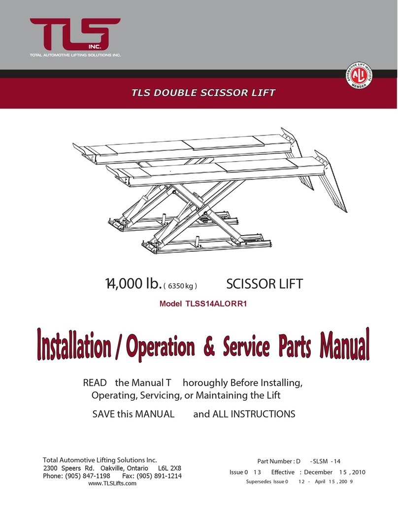
WERTHER INTERNATIONAL STRATOS S39 Instructions for use

I
GB
F
D
E
PONTE SOLLEVATORE A FORBICE
SCISSORS LIFT
PONT ÉLÉVATEUR A CISEAUX
ELEKTROHYDRAULISCHE SCHERENHEBEBÜHNE
ELEVADOR DE TIJERAS
Werther 1-49,79-85,94-95,86 OMA 51-53,4-49,79-85,94-95,87 APAC 55-57,4-49,79-85,94-95,88
ITALGARAGE 59-61,4-49,79-85,94-95,89 TECALEMIT trifase 63-65,4-49,79-85,94-95,90 TECALEMIT monofase
PROLIFT TIP TOP 71-73,4-49,79-85,94-95,92 AUTEC 75-77,4-49,79-85,94-95,93
STRATOS S39
F/15


Manuale di istruzioni per l’uso e la manutenzione del
Instructions and maintenance manual for
Manuel d’instructions pour l’utilisation et l’entretien du:
Bedienungs- und Wartungsanleitung für
Manual de instrucciones para uso y mantenimiento de los
PONTE SOLLEVATORE A FORBICE PER VEICOLI
SCISSORS VEHICLES LIFT
PONT ÉLÉVATEUR A CISEAUX POUR AUTOMOBILES
ELEKTROHYDRAULISCHE SCHERENHEBEBÜHNE
ELEVADORES DE TIJERAS PARA VEHÍCULOS
Modello - Model - Modell - Modèle - Modelos
STRATOS S39
COSTRUTTORE: - MANUFACTURER: - HERSTELLER: - CONSTRUCTEUR: - FABRICANTE:
WERTHER INTERNATIONAL S.p.A.
Via F. BRUNELLESCHI, 12
42124 CADE’ (RE) - ITALY
Telefono ++ / +522 / 9431 (r.a.) - Telefax ++ / +522 / 941997
1aEmissione - 19 Marzo 2010 - 1st Edition - 19 March 2010
1aÉdition - 19 Mars 2010 - 1. Ausgabe - 19 Maerz 2010 - 1ª Edición – 19 Marzo 2010
CENTRO DI ASSISTENZA AUTORIZZATO:
AUTHORISED SERVICE CENTRE:
SERVICE APRÈS-VENTE AGRÉÉ:
KUNDENDIENSTCENTER
CENTRO DE ASISTENCIA AUTORIZADO:
Rev.8 ..........................................29/04/2015
1

Indice
Imballaggio, trasporto e stoccaggio Pag. 4
Introduzione Pag. 6
Cap.1 Descrizione della macchina Pag. 10
Cap.2 Specifiche tecniche Pag.12
Cap.3 Sicurezza Pag.16
Cap.4 Installazione Pag. 20
Cap.5 Funzionamento ed uso Pag. 36
Cap.6 Manutenzione Pag. 38
Cap.7 Inconvenienti e rimedi Pag. 40
Appendice A Informazioni Pag. 44
particolari
Appendice B Parti di ricambio Pag. 46
Contents
Packing, transport and storage Page 4
Introduction Page 6
Chapter 1 Description
of the machine Page 10
Chapter 2 Technical Page 12
specifications
Chapter 3 Safety Page 16
Chapter 4 Installation Page 20
Chapter 5 Operating principles Page 36
and use
Chapter 6 Maintenance Page 38
Chapter 7 Troubleshooting Page 40
Appendix A Special notes Page 44
Appendix B Spare parts Page 46
2

TABLE DES MATIÈRES
Emballage, transport et stockage page 5
Introduction page 7
Chap.1 Description de l’appareil page 11
Chap.2 Caractéristiques techniques page 13
Chap.3 Sécurité page 17
Chap.4 Installation page 21
Chap.5 Fonctionnement page 37
et utilisation
Chap.6 Entretien page 39
Chap.7 Pannes et remèdes page 41
Annexe A Informations page 45
particulières
Annexe B Pièces détachées page 47
Inhaltsverzeichnis
Verpackung, Transport und Lagerung Seite 5
Einleitung Seite 7
Kap.1 Beschreibung Scherenhebebühne Seite 11
Kap.2 Technische Daten Seite 13
Kap.3 Sicherheit Seite 17
Kap.4 Installation Seite 21
Kap.5 Betrieb und Gebrauch Seite 37
Kap.6 Wartung Seite 39
Kap.7 Fehlersuche Seite 41
Anhang A Besondere Informationen Seite 45
Anhang B Ersatzteile Seite 47
INDICE
Embalaje, transporte y almacenaje Pág.5
Introducción Pág.7
Cap. 1 - Descripción de la máquina Pág.11
Cap. 2 - Características técnicas Pág.13
Cap. 3 - Seguridad Pág.17
Cap. 4 - Instalación Pág.21
Cap. 5 - Funcionamiento y uso Pág.37
Cap. 6 - Mantenimiento Pág.39
Cap. 7 - Detección de fallas Pág.41
y remedios
Apéndice A - Información especial Pág.45
Apéndice B - Repuestos Pág.47
3

Fig.1 - Abb.1
Fig.2 - Abb.2
IMBALLAGGIO, TRASPORTO E
STOCCAGGIO
LE OPERAZIONI DI IMBALLAGGIO, SOLLEVA-
MENTO, MOVIMENTAZIONE, TRASPORTO E
DISIMBALLO DEVONO ESSERE AFFIDATE
ESCLUSIVAMENTE A PERSONALE CHE SIA
ESPERTO IN TALI OPERAZIONI E CHE CONOSCA
BENE IL SOLLEVATORE ED IL PRESENTE MANUALE
IMBALLAGGIO E TRASPORTO
IMBALLAGGIO (Fig. 1)
Il sollevatore nelle versioni standard, viene spedito già montato con i
seguenti pezzi:
·N°2 basi e pedane ( P1 - P2 ) chiuse una sull’altra
·N°1 centralina di comando
·N°1 scatola in cartone con kit collegamenti elettrici ed idraulici, tam-
poni in gomma.
NB: Le rampe di salita / discesa / stazionamento vengono spedite con
un imballo a parte.
IATTENZIONE
TRASPORTO (Fig. 2)
L’ imballo può essere sollevato o spostato sia con carrelli elevatori che
con gru o carri ponte.
L’ eventuale imbracatura deve essere accompagnata da una seconda
persona al fine di evitare pericolose oscillazioni del carico.
All’ arrivo, verificare che la merce non abbia subito danni durante il tra-
sporto e che ci siano tutti i pezzi indicati nella lista di spedizione. Comu-
nicare immediatamente all’ incaricato o al trasportatore le eventuali
mancanze o irregolarità e eventuali danni che il sollevatore abbia subito
durante il trasporto.Rispettare, infine, al momento dello scarico o del
carico della merce i propri punti di presa come indicato in figura.
PACKING, TRANSPORT AND STORAGE
ALL PACKING, LIFTING, HANDLING, TRANSPORT
AND UNPACKING OPERATIONS ARE TO BE
PERFORMED EXCLUSIVELY BY PERSONNEL WITH
KNOWLEDGE OF THE LIFT AND THE CONTENTS OF
THIS MANUAL
PACKING AND TRANSPORT
PACKING (Fig. 1)
Standard versions of the lift are dispatched previously assembled and
equipped as follows:
·No. 2 bases and platforms (P1-P2), one closed onto the opther;
·No. 1 control box;
·No. 1 cardboard box equipped with electric and hydraulic connec-
tions, rubber pads.
Note: lifting, lowering and placing ramps are delivered in a separate
package.
IWARNING
TRANSPORT (fig. 2)
Packing can be lifted or moved by lift trucks, cranes or bridge cranes.
In case of slinging, a second person must always take care of the load,
in order to avoid dangerous oscillations.
At the arrival of the goods, check for possible damage due to transport
operations. Also verify that all items specified in the delivery notes are
included. In case of missing parts, possible defects or damages due to
transport, the person in charge or the carrier must be immediately infor-
med.
Furthermore, during loading and unloading operations goods must be
handled as shown in the picture.
4

EMBALLAGE, TRANSPORT ET
STOCKAGE
LES OPÉRATIONS D’EMBALLAGE, DE
MANIPULATION, DE TRANSPORT ET DE
DÉBALLAGE DEVRONT ÊTRE CONFIÉES
EXCLUSIVEMENT À UN PERSONNEL EXPÉRIMENTÉ
DANS CE TYPE D’OPÉRATIONS, CONNAISSANT
BIEN L’ÉLÉVATEUR ET LE PRÉSENT MANUEL.
Emballage et transport
EMBALLAGE (Fig.1)
L’élévateur est expédié démonté et se présente comme suit:
·2 plates-formes (P1-P2) refermées et posées l’une sur l’autre
·1 pupitre de commande
·1 carton contenant les éléments de raccordement hydrauliques et
électriques et les tampons en caoutchouc.
N.B.: Les rampes de montée/descente/stationnement font l’objet d’un
colis à part.
IATTENTION
Transport (Fig. 2)
Le colis peut être soulevé et déplacé soit avec un chariot élévateur, soit
à l’aide d’une grue ou d’un pont roulant.
En cas d’élingage, le colis devra être accompagné par une seconde
personne afin d’éviter toute oscillation dangereuse de la charge.
A la réception, s’assurer que le matériel n’ait subi aucune avarie durant
le transport et que tous les éléments indiqués sur le bordereau de coli-
sage soient présents.
Communiquer immédiatement au transporteur ou au livreur les man-
quants éventuels ou les avaries que l’élévateur pourrait avoir subi du-
rant le transport. Respecter, enfin, lors du déchargement ou du charge-
ment des colis, les points de prise indiqués sur la figure 2.
Transport, Verpackung und Lagerung
ALLE VERPACKUNGS- HEBE-, BEHANDLUNGS-,
TRANSPORT UND AUSPACK – ARBEITEN SIND NUR
VON AUSGEBILDETEM FACHPERSONAL, DAS
KENNTNISSE DES LIFTS UND DER BEDIENUNGSAN-
WEISUNG BESITZT, DURCHZUFÜHREN.
Verpackung und Transport
Verpackung ( Abbildung 1)
Die Standard Ausrüstungen des Lifts werden vordemontiert zum Ver-
sand gebracht und bestehen aus folgenden Baugruppen:
·2 Stück Grundrahmen und den Aufnahmeplattformen (P1-P2)
·1 Stück Schaltschrank
·1 Stück karton mit elektrischen und hydraulischen Verbindungen, 4
Stück Gummiaufnahmen.
Notiz: Die Auf- und Abfahrrampen werden bei Bedarf separat verpackt
geliefert.
I
WARNUNG
TRANSPORT (Abb. 2)
Das Packgut kann mittels Hubwagen, Kränen oder Brückenkränen ge-
hoben und bewegt werden.
Beim hängendem Transport muß immer eine zweite Person anwesend
sein, um dafür Sorge zu tragen, daß gefährliche Schwingungen vermie-
den werden.
Bei Ankunft der Ware, unverzüglich auf Transportschäden untersuchen.
Ebenfalls sollten verglichen werden, ob alle im Lieferschein angegebe-
nen Artikel in den Kisten enthalten sind. Im Falle von fehlenden Teilen,
möglichen Defekten oder Beschädigungen muß die entsprechende Per-
son oder der Transporteur unverzüglich benachrichtigt werden.
Ferner müssen die zu behandelnden Güter während der Lade- und Ab-
ladearbeiten wie in der Abbildung gezeigt, behandelt werden.
EMBALAJE, TRANSPORTE Y
ALMACENAJE
LAS OPERACIONES DE EMBALAJE, TRANSPORTE,
DESIMBALAJE DEBEN SER EFECTUADAS POR
PERSONAL QUE TENGA EXPERIENCIA EN DICHAS
OPERACIONES Y QUE CONOZCA BIEN EL
ELEVADOR Y ESTE MANUAL.
EMBALAJE Y TRANSPORTE
EMBALAJE (Fig. 1)
El elevador en la versión standard, se suministra con los siguientes
componentes:
·N° 2 bases y peanas (P1 y P2) cerradas una sobre la otra.
·N° 1 centralita de mandos
·N° caja de cartón con el juego de tubos y racores para la conexión
hidráulica, tacos de goma y pies de regulación
·N° 1 juego de rampas de subida/descenso (en caso de que no se
quiera empotrar el elevador)
I¡ATENCION!
TRANSPORTE (Fig. 2)
El embalaje puede ser elevado y trasladado con camión de plataforma,
camión de grúa ó grúa de puente.
En caso de tirar con una estinga, una segunda persona debe cuidar
siempre de la carga, para evitar oscilaciones peligrosas.
A la llegada del género, verifique los posibles daños producidos duran-
te el transporte. También verifique que todos los artículos especificados
en las notas de entrega estén incluidos. En caso de pérdidas, posibles
defectos o daños debidos al transporte, debe informarse inmediata-
mente de ello al transportista, haciéndolo constar en la nota de entrega.
Además, durante la carga y la descarga, el género debe manejarse
como muestra la figura.
5

INTRODUZIONE
IATTENZIONE
Questo manuale è stato scritto per il personale di officina addetto
all’uso del sollevatore (operatore) e per il tecnico addetto alla ma-
nutenzione ordinaria (manutentore) pertanto, prima di effettuare
qualsiasi operazione sul sollevatore e/o sul suo imballaggio, oc-
corre leggere attentamente tutto il manuale, poichè esso contiene
informazioni importanti per:
- LA SICUREZZA DELLE PERSONE addette all’uso ed alla manu-
tenzione ordinaria,
- LA SICUREZZA DEL SOLLEVATORE,
- LA SICUREZZA DEI VEICOLI sollevati.
CONSERVAZIONE DEL MANUALE
Il manuale è parte integrante del sollevatore e deve sempre accom-
pagnarlo, anche in caso di vendita.
Esso deve sempre essere conservato in vicinanza del sollevatore, in
luogo facilmente accessibile.
L’operatore ed il manutentore devono poterlo reperire e consultare rapi-
damente in qualsiasi momento.
SI RACCOMANDA, IN PARTICOLARE, UNA LETTURA ATTENTA E
RIPETUTA DEL CAPITOLO 3, CHE CONTIENE IMPORTANTI INFOR-
MAZIONI E AVVISI RELATIVI ALLA SICUREZZA.
Il sollevatore è stato progettato e costruito rispettando quanto segue:
LEGGI:
Direttive Europee
2004/108/CE - 2006/42/CE - 2006/95/CE
NORME TECNICHE :
Norme Europee
EN 1493-2010 / EN ISO 12100/1 2005 - EN ISO 12100/2 2005
IMPIANTO ELETTRICO
EN 60204-1
Il sollevamento, il trasporto, il disimballo, il montaggio, l’installazione e
la messa in servizio, la taratura e le registrazioni iniziali, la manutenzio-
ne STRAORDINARIA, la riparazione, la revisione, lo spostamento e lo
smantellamento del sollevatore devono essere eseguiti dai tecnici spe-
cializzati dei RIVENDITORI AUTORIZZATI o dei CENTRI ASSISTEN-
ZA AUTORIZZATI dal Costruttore (vedere centro assistenza autoriz-
zato indicato nel frontespizio):
Il costruttore non risponde di alcun danno a persone, veicoli od
oggetti causati dagli interventi sopracitati se effettuati da persona-
le non autorizzato o da un uso improprio o non consentito del sol-
levatore
INTRODUCTION
IWARNING
This manual has been prepared for workshop personnel expert in
the use of the lift (operator) and technicians responsible for routi-
ne maintenance (maintenance fitter); read the manual before car-
rying out any operation with the lift and/or its packing. This manual
contains important information regarding:
- THE PERSONAL SAFETY of operators and maintenance workers,
- LIFT SAFETY,
- THE SAFETY OF LIFTED VEHICLES
CONSERVING THE MANUAL
The manual is an integral part of the lift , which it should always
accompany , even if the unit is sold.
The manual must be kept in the vicinity of the lift, in an easily accessi-
ble place.
The operator and maintenance staff must be able to locate and consult
the manual quickly and at any time.
ATTENTIVE AND REPEATED READING OF CHAPTER 3 , WHICH
CONTAINS IMPORTANT INFORMATION AND SAFETY WARNINGS,
IS PARTICULARLY RECOMMENDED.
Lift rack has been designed and built in compliance with the following:
LAWS
European directives
2004/108/CE - 2006/42/CE - 2006/95/CE
TECHNICAL STANDARDS
European standards
EN 1493-2010 / EN ISO 12100/1 2005 - EN ISO 12100/2 2005
ELECTRIC PLANT
EN 60204-1
The lifting, transport, unpacking, assembly, installation, starting up, ini-
tial adjustment and testing, EXTRAORDINARY maintenance, repair,
overhauls, transport and dismantling of the lift must be performed by
specialised personnel from the LICENSED DEALER or an SERVICE
CENTRE authorised by the manufacturer (see authorised dealer on
frontispiece).
The manufacturer declines all responsibility for injury to persons
or damage to vehicles or objects when any of the above mentioned
operations has been performed by unauthorised personnel or
when the rack has been subject to improper use.
6

INTRODUCTION
IATTENTION
Ce manuel a été rédigé pour le personnel d’atelier affecté à l’utilisation
de l’élévateur (opérateur) et pour l’agent affecté à l’entretien courant,
toutefois, avant d’effectuer quelque opération que ce soit sur l’élévate-
ur et/ou sur son emballage, il est nécessaire de lire attentivement tout
le manuel, car celui-ci contient des informations importantes pour:
- LA SÉCURITÉ DES PERSONNES affectées à l’utilisation et à
l’entretien courant,
- LA SÉCURITÉ DE L’ÉLÉVATEUR,
- LA SÉCURITÉ DES VÉHICULES soulevés.
CONSERVATION DU MANUEL
Ce manuel fait intégralement partie de l’élévateur et doit toujours
l’accompagner, même en cas de revente.
Il devra toujours être conservé à proximité de l’élévateur, dans un en-
droit facilement accessible.
A tout moment, l’opérateur et l’agent d’entretien devront pouvoir y avoir
recours rapidement.
EN PARTICULIER, IL EST RECOMMANDé UNE LECTURE
ATTENTIVE ET RéPéTéE DU CHAPITRE 3, QUI CONTIENT DES
INFORMATIONS ET DES CONSIGNES DE SéCURITé.
L’élévateur a été conçu et construit en respect des dispositions suivantes:
LOIS
Directives européennes
2004/108/CE - 2006/42/CE - 2006/95/CE
NORMES TECHNIQUES
Norme européenne
EN 1493-2010 / EN ISO 12100/1 2005 - EN ISO 12100/2 2005
ÉQUIPEMENT ÉLECTRIQUE
EN 60204-1
La manutention, le transport, le déballage, le montage, l’installation et la
mise en service, le tarage et les réglages initiaux, l’entretien
EXTRAORDINAIRE, la réparation, la révision, le déplacement ou le dé-
mantèlement de l’élévateur devront être exécutés par les techniciens
spécialisés des REVENDEURS AUTORISéS ou des CENTRES DE
SERVICE APRès-vente AGRééS par le constructeur (voir l’adresse
indiquée en première page).
Le constructeur dégage toute responsabilité concernant les dom-
mages aux personnes, véhicules et biens causés par les interven-
tions citées ci-dessus si elles sont effectuées par un personnel
non autorisé ou par une utilisation de l’élévateur inadaptée et non
prévue.
EINLEITUNG
IACHTUNG
Dieses Handbuch wurde für das mit der Bedienung der Scherenhe-
bebühne beauftragte Werkstattpersonal (Bediener) und für den
mit der Wartung beauftragten Techniker verfaßt. Daher ist vor je-
dem Eingriff an der Scherenhebebühne oder an dem Verpackungs-
material aufmerksam dieses Handbuch zu lesen, denn dieses ent-
hält wichtige Informationen für:
- die Sicherheit der mit der BEDIENUNG UND DER WARTUNG be-
auftragten Personen
- DIE SICHERHEIT DER Scherenhebebühne
AUFBEWAHRUNG DES HANDBUCHES
Das Handbuch stellt ein Teil der Scherenhebebühne dar und muß diese
immer begleiten, auch wenn die Scherenhebebühne verkauft wird
Das Handbuch muß immer an einem leicht zugänglichen Ort in der
Nähe der Scherenhebebühne aufbewahrt werden
Der Bediener und die mit der Wartung beauftragte Person müssen das
Handbuch jederzeit zur Verfügung haben
INSBESONDERE WIRD EMPFOHLEN. DAS KAPITEL 3 WIEDER-
HOLT ZU LESEN. DENN DIESES KAPITEL ENTHÄLT WICHTIGE IN-
FORMATIONEN UND HINWEISE BEZÜGLICH DER SICHERHEIT
Die Scherenhebebühne wurde konstruiert und hergestellt unter Beach-
tung der folgenden Vorschriften:
GESETZE
Europäische Richtlinien
2004/108/CE - 2006/42/CE - 2006/95/CE
TECHNISCHER STANDARD
Europäischer Standard
EN 1493-2010 / EN ISO 12100/1 2005 - EN ISO 12100/2 2005
Elektrik
EN 60204-1
Hub, Transport, Auspacken, Montage, Installation und Inbetriebnahme,
Eichung und Ersteinstellungen, AUSSERGEWÖHNLICHE Wartung,
Reparatur, Überholung, firmeninterner Transport und Abrüstung der
Scherenhebebühne müssen von Fachmännern der vom Hersteller „
KUNDENDIENSTSORT“ ausgeführt werden (siehe auf der Titelseite
angegebenes Kundendienstzentrum).
Der Hersteller haftet nicht für Personen- und Sachschäden, die auf
die o.g. Eingriffe zurückzuführen sind, falls diese von nicht zuge-
lassenem Personal ausgeführt wurden oder auf einen unsachge-
mäßen Gebrauch der Scherenhebebühne beruhen.
INTRODUCCIÓN
IATENCIÓN
Este manual ha sido escrito para el personal de taller que se ocu-
pa del uso del elevador (operario) y para el técnico que se ocupa
del mantenimiento ordinario (servicio) por tanto, antes de realizar
cualquier operación en el elevador y/o en su embalaje, es preciso
leer atentamente todo el manual, ya que contiene informaciones
importantes para:
- LA SEGURIDAD DE LAS PERSONAS que se ocupan del uso y del
mantenimiento ordinarios
- LA SEGURIDAD DEL ELEVADOR,
- LA SEGURIDAD DE LOS VEHÍCULOS elevados.
CONSERVACIÓN DEL MANUAL
El manual es parte integrante del elevador y debe acompañarlo siem-
pre, aun en caso de venta.
Deberá estar cerca del elevador, en lugar fácilmente accesible.
El operario y el personal de servicio lo deberá hallar rápidamente para
consultar en cualquier momento.
SE RECOMIENDA, PARTICULARMENTE, UNA LECTURA ATENTA Y
REPETIDA DEL CAPÍTULO 3, QUE CONTIENE IMPORTANTES
INFORMACIONES Y AVISOS RELATIVOS A LA SEGURIDAD.
Los elevadore han sido proyectados y fabricados respectando las si-
guientes:
LEYES
Directivas europeas
2004/108/CE - 2006/42/CE - 2006/95/CE
NORMAS TÉCNICAS
Normas europeas
EN 1493-2010 / EN ISO 12100/1 2005 - EN ISO 12100/2 2005
EQUIPO ELÉCTRICO:
EN 60204-1
La elevación, el transporte, el desembalaje, el montaje, la instalación y
puesta en funcionamiento, la verificación y los ajustes iniciales, el man-
tenimiento EXTRAORDINARIO, la reparación, la revisión, la manipula-
ción y el desmantelamiento del elevador deben ser ejecutados por los
técnicos especializados del REVENDEDOR AUTORIZADO o por los
CENTROS DE ASISTENCIA AUTORIZADOS del Fabricante (ver cen-
tro de asistencia autorizado indicado al principio).
El fabricante no responde de daños a personas, vehículos u obje-
tos causados por las intervenciones antes citadas si se han efec-
tuado por personal no autorizado o por un uso impropio o no con-
sentido del elevador.
7

Per tutte queste attività vengono indicati, nel presente manuale, soltan-
to gli aspetti (operativi e di sicurezza) che possono essere utili anche
all’operatore ed al manutentore per comprendere meglio la struttura ed
il funzionamento del sollevatore e per un suo migliore utilizzo.
Per comprendere il linguaggio adottato nel presente manuale, l’operato-
re deve possedere esperienza specifica nelle attività di officina, di assi-
stenza, manutenzione e riparazione dei veicoli nonchè la capacità di in-
terpretare correttamente i disegni e le descrizioni riportate nel manuale
e la conoscenza delle norme antinfortunistiche generali e specifiche vi-
genti nel paese in cui viene installato il sollevatore.
Gli stessi criteri valgono per la scelta del tecnico manutentore che do-
vrà, inoltre, possedere le conoscenze tecniche specifiche e specialisti-
che (meccaniche, elettriche) necessarie per effettuare in sicurezza gli
interventi previsti nel manuale.
Nel testo del manuale troverete spesso le diciture “operatore” e “ma-
nutentore” il cui significato è il seguente:
OPERATORE: persona addetta all’uso del sollevatore.
MANUTENTORE: persona addetta alla manutenzione ordinaria del sol-
levatore.
This manual indicates only the operative and safety aspects that may
prove useful to the operator and maintenance worker, in better under-
standing the structure and operation of the lift and for best use of the
same.
In order to understand the terminology used in this manual, the operator
must have specific experience in workshop, service, maintenance and
repair activities, the ability to interpret correctly the drawings and de-
scriptions contained in the manual and be acquainted with the general
and specific safety rules relevant to the country in which the machine
has been installed.
The same applies to the maintenance fitter, who must also possess
specific and specialised knowledge (mechanical, engineering) needed
to perform the operations described in the manual in complete safety.
The words “operator” and “maintenance fitter” used in this manual are
construed as follows:
OPERATOR: person authorised to use the lift
MAINTENANCE FITTER: person authorised for routine maintenance of
the lift.
8

Pour toutes ces opérations, sont indiqués dans ce manuel, seulement
les aspects (méthode et sécurité) qui peuvent être utiles à l’opérateur et
à l’agent d’entretien pour mieux comprendre la structure et le fonction-
nement de l’élévateur, en vue d’une meilleure utilisation.
Pour comprendre les termes utilisés dans le présent manuel,
l’opérateur doit posséder un expérience spécifique dans le domaine de
l’atelier, le dépannage, l’entretien et la réparation des véhicules, ainsi
que la capacité d’interpréter les dessins et descriptions présents dans
ce manuel, et la connaissance des normes de prévention des accidents
du travail et des règlements spécifiques en vigueur dans le pays où est
installé l’élévateur.
Les mêmes critères sont à prendre en considération pour le choix de
l’agent d’entretien qui devra, en plus, posséder les connaissances spé-
cifiques et spécialisées (mécanique, électricité) nécessaires pour effec-
tuer en toute sécurité les interventions prévues dans ce manuel.
Dans le texte de ce manuel, vous trouverez souvent les mots “opérate-
ur” et “agent d’entretien” dont la signification est la suivante:
OPÉRATEUR: personne affectée à l’utilisation de l’élévateur
AGENT D’ENTRETIEN: personne affectée à l’entretien courant de
l’élévateur.
Für all diese Eingriffe wird im vorliegenden Handbuch nur auf die
Aspekte (Bedienung und Sicherheit) eingegangen, die auch für den Be-
diener und den Wartungsfachmann nützlich sind, damit diese besser
über den Betrieb und die Wartung der Scherenhebebühne unterrichtet
sind.
Zum Verständnis der in diesem Handbuch verwendeten Fachbegriffe
muß der Bediener über eine spezifische Werkstattfachkenntnis sowie
über eine Fachkenntnis bei der Wartung und der Reparatur der Fahr-
zeuge verfügen. Er muß ferner in der Lage sein, die in diesem Hand-
buch enthaltenen Zeichnungen und Beschreibungen korrekt auslegen
zu können und über die allgemeinen und spezifischen Unfallverhü-
tungsmaßnahmen des jeweiligen Landes, in dem die Scherenhebebüh-
ne aufgestellt wird, unterrichtet sein.
Die gleichen Kriterien gelten auch für den Wartungsfachmann, der fer-
ner auch über die technischen Spezifikationen und fachbezogenen
Kenntnisse (mechanische, elektrische Fachkenntnisse) verfügen muß,
die für die Ausführung der in diesem Handbuch vorgesehenen Eingriffe
unter Sicherheitsbedingungen erforderlich sind.
Im Text dieses Handbuches werden oft die Begriffe, Bediener“ und
„Wartungsfachmann “ verwendet. Diese Begriffe besitzen folgende
Bedeutung:
BEDIENER: Person, die mit dem Bedienen der Scherenhebebühne
beschäftigt ist.
WARTUNGSFACHMANN: Person, die mit der Wartung der Scherenhe-
bebühne beauftragt ist.
Para todas estas actividades se indican en el presente manual, sola-
mente los aspectos operativos y de seguridad que pueden ser útiles al
usuario y al encargado del mantenimiento para comprender perfecta-
mente la estructura y el funcionamiento del elevador y para utilizarlo
correctamente.
Para comprender el lenguaje usado en este manual, el operario debe
tener experiencia específica en las actividades de taller, de asistencia,
mantenimiento y reparación de vehículos así como la capacidad de in-
terpretar correctamente los dibujos y descripciones indicades en el ma-
nual y el conocimiento de las normas preventivas generales y específi-
cas vigentes en el país donde se instala el elevador.
Idénticos criterios son válidos para la elección del técnico de manteni-
miento que deberá, además, poseer los conocimientos específicos y de
especialización (mecánico, eléctrico) necesarios para realizar con se-
guridad las intervenciones previstas en el manual.
En el texto del manual se encontrará a menudo las frases “operario” y
“personal de servicio” cuyos significados son los siguientes:
OPERARIO: persona que se ocupa del uso del elevador.
PERSONAL DE SERVICIO: persona que se ocupa del mantenimiento
ordinario del elevador.
9

Fig. 3 - Abb.3
CAP.1. DESCRIZIONE DELLA MACCHINA
Il ponte sollevatore a forbice è adatto a sollevare tutti i tipi di autovetture e
furgoni con peso non superiore a 4000 Kg. E’ ad altezza variabile, in modo
da dare la possibilità all’ utilizzatore di operare con tranquillità e sicurezza all’
altezza desiderata. E’ fornito di pedana con prolunghe integrate, che permet-
tono il sollevamento di tutte quelle autovetture con passo più lungo.Il solleva-
tore a forbice soddisfa tutte le esigenze di: autoriparatori, gommisti, carroz-
zieri e operatori del settore.
Il ponte sollevatore è fisso, cioè ancorato al suolo. Può essere fornito sia a
pavimento che ad incasso, ed è stato progettato per il sollevamento e lo sta-
zionamento in quota di autoveicoli e furgoni.
CARATTERISTICHE:
·comandi a bassa tensione ( 24 v );
·sincronismo idraulico-volumetrico delle pedane senza barra di accop-
piamento;
·dispositivo di arresto discesa in caso di ostacolo;
·doppio circuito idraulico dotato di elettrovalvole di sicurezza contro la
rottura dei tubi;
·dispositivo per la discesa manuale in caso di assenza di corrente.
·dispositivo acustico di segnalazione e sicurezza per il consenso al-
l’ultimo tratto discesa pedane.
·valvola di portata max
·valvola controllo velocità di discesa
Il sollevatore è composto da:
- BASAMENTO ( gruppo struttura fissa )
- BRACCI, PEDANA ( gruppo struttura mobile e di sollevamento )
- CENTRALINA DI COMANDO.
GRUPPO STRUTTURA FISSA:
E’ costituita dalla base del ponte sollevatore, costruita in una struttura
in lamiera di acciaio sagomato con fori di fissaggio al suolo.
GRUPPO STRUTTURA MOBILE E DI SOLLEVAMENTO:
E’ costituita da bracci in tubolare di acciaio sagomato. La pedana portante è
costituita da longheroni portanti in tubolare di acciaio, collegati tra loro con
montanti ancorati ai bracci con perni di acciaio nei punti fissi e con rulli nei
punti mobili.Tutte le articolazioni del sistema di sollevamento sono munite di
boccole autolubrificanti esenti da manutenzione.
CENTRALINA DI COMANDO:
E’ formata da un box metallico contenente nella parte inferiore il serbatoio
olio idraulico e il gruppo pompa-motore. Nella parte superiore sono alloggiati
i comandi.
IATTENZIONE
Il ponte sollevatore è stato costruito per il sollevamento e lo stazionamento in
quota dei veicoli in ambiente chiuso. Ogni altro uso non è consentito, ed in
particolare esso non è idoneo per operazoni di: lavaggio, verniciatura,solle-
vamento di persone, ponteggio, cric per sollevare o cambiare ruote.
CHAP. 1 DESCRIPTION OF THE MACHINE
Scissor lift is able to lift any kind of car and van whose weight is not hi-
gher than 4000 Kg. The height is adjustable so that it can be easily and
safely operated as needed. On request it can be equipped with exten-
sion platforms to lift cars with a longer wheelbase. Our scissor lift can
meet any demand coming from car repairmen, tyre dealers, body repa-
irmen and from all those who work in this field.
Scissor lift is fixed, that is anchored to the ground. It can be supplied in
both platform or recessed version and it has been designed and built for
car and van lifting and placing operations.
FEATURES:
·low-voltage controls (24v);
·hydraulic-volumetric synchronism of platforms without any track bar;
·Descent stopping device in case of any obstacle.
·dual hydraulic circuit with solenoid valves that protect against pipe
breakage
·device for manual lowering in case of power failure.
·acoustic alarm and dual control for last phase of down travel of the
platforms.
·pressure relief valve
·lowering speed control valve
Our car lift iis equipped as follows:
- BASE (fixed structure);
- ARMS, PLATFORM (lifting and unfixed structure);
- CONTROL BOX.
FIXED STRUCTURE UNIT:
It consists of the car lift base, which is made of profiled steel sheet with
clamping holes.
LIFTING AND UNFIXED STRUCTURE UNIT:
It is composed by the arms made of profiled steel tubes. The load-car-
rying platform is made of tubolar steel pieces linked to each other by
vertical rods anchored to the arms by steel pins at the fixed points and
by rollers at the moveable ones. All lifting system links are equipped
with self-lubricating bushings where servicing is not required.
CONTROL BOX:
It is a metal box containing, at the bottom, the hydraulic oil tank and the
motor-pump set, and on top, all the controls.
IWARNING
Scissor lift is designed and built to lift vehiclesand hold them in the ele-
vated pèosition in a closed workshop. All other use are unauthorised. In
particular, the lift is not suitable for: washing and respray work, creating
raised platforms or lifting personnel, use as a makeshift, use as goods
lift, use as a jack for lifting vehicles or changing wheels.
10
Base
Base
Embase
Grundrahmen
Base
Pedana
Platform
Plate-forme
Aufnahmeplattform
Plataforma
Bracci
Arms
Bras
Doppelschere
Brazos
Gruppo struttura fissa
Fixed structure unit
Groupe structure fixe
Feste Struktur - Einheit
Estructura fija
Gruppo struttura mobile
Unfixed structur unit
Groupe structure mobile
Bewegliche Struktur - Einheit
Estructura móvil y de alzamiento

CHAP. 1 DESCRIPTION DE L’APPAREIL
Cet élévateur à ciseaux est conçu pour soulever tous types de véhicules au-
tomobiles et de fourgons d’un poids maximal de 4000 kg. Il est à hauteur va-
riable, de façon à permettre à l’utilisateur de travailler commodément et en
sécurité à la hauteur désirée. Il est équipé de plates-formes avec rallonges
intégrées qui permettent le levage de tous les véhicules à empattement ral-
longé. Cet élévateur à ciseaux satisfait toutes les exigences dans le domaine
de la réparation automobile, des pneumatiques, de la carrosserie et autres
activités liées au secteur de l’automobile.
L’élévateur est fixe, c’est à dire ancré au sol. Il peut être fourni en version à
encastrer ou à poser au sol, il a été conçu pour le levage et le stationnement
en hauteur de véhicules automobiles et de fourgons.
CARACTÉRISTIQUES
·commandes basse tension 24V;
·synchronisme hydro-volumétrique des plates-formes, sans barre
d’accouplement;
·dispositif d’arrêt descente en cas d’obstacle:
·double circuit hydraulique doté d’électrovannes de sécurité contre la
rupture des tuyaux;
·dispositif de descente manuel en cas de coupure de courant;
·dispositif acoustique de signalisation et de sécurité pour l’accord au
dernier segment de descente des plates-formes.
·vanne de portée max.;
·vanne de contrôle vitesse de descente.
L’élévateur se compose de:
-EMBASES (groupe structure fixe)
-BRAS ET PLATES-FORMES (groupe structure mobile)
-PUPITRE DE COMMANDE
GROUPE STRUCTURE FIXE:
Il se compose des embases des plates-formes construites en tôle
d’acier façonnée et portant des trous pour la fixation au sol.
GROUPE STRUCTURE MOBILE DE SOULÈVEMENT:
Il est composé de bras en tube d’acier et de plates-formes constituées par
les longerons porteurs en tube d’acier reliés entre eux par des montants sur
lesquels les bras viennent se fixer par l’intermédiaire d’axes en acier aux po-
ints fixes et de rouleaux aux points mobiles. Toutes les articulations de
l’ensemble sont équipées de bagues autolubrifiantes ne nécessitant aucun
entretien.
PUPITRE DE COMMANDE
Il se compose d’un caisson métallique contenant à la partie inférieure le ré-
servoir d’huile et le groupe moteur-pompe. A la partie supérieure sont placé-
es les commandes.
IATTENTION
Cet élévateur a été construit pour l’élévation et le stationnement en charge
de véhicules automobiles dans un local fermé. Tout autre usage est interdit,
et en particulier il ne doit pas être utilisé pour les opérations de lavage, de
peinture, pour l’élévation de personnes, comme échafaudage, comme pres-
se pour écraser ou comme cric pour soulever ou changer des roues.
KAPITEL 1 Beschreibung Scherenhebebühne
Mit Scherenhebebühnen können jegliche Arten von Autos oder Lieferwagen
bis zu einem Gewicht von 4000 kg gehoben werden. Die Höhe ist verstell-
bar, so daß einfacher und sicherer Betrieb, wie benötigt, durchgeführt wer-
den kann. Auf Anfrage ist eine Zusatzaufnahme lieferbar, um auch Autos mit
längerer Achsenabständen heben zu können. Unser Scherenhebebühne
kann alle Anforderungen von Autoschlossern, Reifenhändlern, Karosserie-
schlossern und allen in diesem Bereich Beschäftigten erfüllen. Die Scheren-
hebebühne ist fest im Boden verankert Die Scherenhebebühne kann sowohl
in einer Aufflur- als auch in der Unterflur- Ausführung geliefert werden.
EIGENSCHAFTEN
·Steuerungspannung (24 V)
·Hydraulisch-volumetrischer Synchronismus zur Steuerung der Hebe-
zylinder
·Stopp-Taste beim Herunterfahren im Falle eines Hindernisses
·Doppelter Hydraulikkreis mit Sicherheitsventilen gegen Platzen der
Schläuche;
·Mechanische Sicherheitssperren
·Vorrichtung zum manuellen Absenken bei Strom Ausfall
·Höchstdruckventil
·Absenkgeschwindigkeitskontrollventil
Die Scherenhebebühne besteht aus den folgenden Baugruppen:
- Grundrahmen ( feste Struktur)
- Doppelschere, Aufnahmeplattform (bewegliche Struktur)
- Schaltschrank
Feste Struktur - Einheit
Bestehend aus dem Grundrahmen, hergestellt aus profiliertem Stahl-
blech mit verstärkten Befestigungslöchern.
Bewegliche Struktur - Einheit
Bestehend aus den Scherenarmen aus profilierten Stahlrohren. Die Aufnah-
meplattform ist aus rohrförmigen Stahlteilen hergestellt, die durch vertikale
Stangen verbunden sind und mittels Stahlbolzen an den festen Punkten und
mittels Rollen an den beweglichen Teilen befestigt sind.
Alle Verbindungen des Hebe – Systems sind mit selbstschmierenden Buch-
sen ausgestattet.
Schaltschrank
Metallgehäuse, in dem unten der hydraulische Öltank und Motor (Pumpen-
satz) mit den erforderlichen hydraulischen und elektrischen Steuerelemente
untergebracht sind..
I!!! WARNUNG !!!
Die Scherenhebebühne wurde konstruiert und gefertigt, um in einer ge-
schlossenen Werkstatt Fahrzeuge zu heben und diese in der erhöhten Posi-
tion festzuhalten. Alle sonstigen Einsätze sind nicht erlaubt.
Im einzelnen: der Lift ist nicht geeignet für Wasch- und Lackierbetriebe, Ein-
richten von steigenden Plattformen oder Heben von Personen, oder Einsatz
als Warenlift Notbehelfspresse für Zerkleinerungszwecke, Einsatz als Winde
zum Heben von Fahrzeugen oder Radwechsel.
CAPITULO 1 - Descripcion de la maquina
El elevador de tijeras es apto para levantar todos los tipo de vehículos
con peso de hasta 4,0 toneladas. Es de altura variable para permitir al
usuario de trabajar con toda transquilidad y seguridad a la altura dese-
ada. Se suministra con extensiones integradas que permiten alzar to-
dos los vehículos de larga distancia entre ejes. Este elevador puede
satisfacer las necesidades de: mecánicos, neumatiqueros, reparadores
de carrocerías y operadores del sector.
El elevador es fijo, o sea clavado al suelo. Puede ser suministrado tan-
to para empotrar como para ser colocado en el piso.
CARACTERISTICAS:
·Controles de baja tensión (24 V)
·Sincronización hidráulica y volumétrica de las plataformas sin barra
de conexión
·dispositivo de parada en bajada en caso de obstaculo
·doble circuito hidráulico con electroválvula de seguridad contra la
rotura de los tubos;
·Dispositivo de descenso manual en caso de falta de corriente
·Dispositivo acústico de seguridad para permitir el descenso del últi-
mo tramo de las plataformas
·válvula de carga máx.
·válvula de control velocidad de descenso
El elevador está formado por:
-BASE (estructura fija)
-BRAZOS, PLATAFORMAS (estructura móvil de elevación)
-CENTRAL DE MANDOS
ESTRUCTURA FIJA:
Consta de la base del elevador, una estructura de chapa de acero per-
filado con agujeros de sujeción al suel.
ESTRUCTURA MOVIL Y DE ALZAMIENTO
Consta de brazos de acero tubular perfilado. La plataforma de soporte
está formada por piezas de acero tubular conectados entre ellos a tra-
vés de barras verticales anclados a los brazos con pasadores de acero
en los puntos fijos y con rodillos en los puntos móviles. Todas las arti-
culaciones del sistema de elevación están equipadas con casquillos
autolubricantes que no requieren mantenimiento.
CENTRAL DE MANDOS:
Consta de una caja metálica que contiene en la parte inferior el depó-
sito de aceite hidráulico y el grupo bomba-motor. En la parte superior
están ubicados los botones de mando.
I¡ATENCION!
El elevador ha sido fabricado para alzar los vehículos en lugares cerra-
dos. No se permite otro uso: especialmente el elevador no es apto para
operaciones de lavado, pintado, alzamiento de personas, prensa.
11

Fig. 4 - Abb.4
CAP.2 SPECIFICHE TECNICHE
DATI TECNICI:
Funzionamento ..................................................elettro-idraulico
Portata ................................................................4000 Kg
Tempo di salita ...................................................35 sec.
Tempo di discesa................................................45 sec.
Alimentazione pneumatica..................................4:8 bar
Rumorosità..........................................................<74 db
Peso totale..........................................................circa 660 Kg
Temperatura di funzionamento...........................-10°C / +50°C
Ambiente di lavoro: locale chiuso.
Il senso di rotazione del motore è sinistro, cioè antiorario, come indicato
dalla targhetta sul motore stesso.
MOTORE ELETTRICO
Tipo ...........................................................G 80
Potenza .....................................................2.2 Kw
Tensione....................................................230-400 V trif. +/- 5%
Frequenza .................................................50 Hz
N° poli........................................................2
Velocità .....................................................2800 giri/1’
Forma costruttiva.......................................B14
Classe isolamento.....................................F
Assorbimento: ...........................................230V: 14.4A
..................................................................400V: 7,5A
Servizio .....................................................S3 12min
Protezione .................................................IP54
Il collegamento del motore deve essere eseguito riferendosi agli schemi
elettrici allegati. Il senso di rotazione del motore è sinistro (antiorario)
come indicato nella targhetta applicata sul motore stesso.
CENTRALINA OLEODINAMICA:
Pompa.......................................................ad ingranaggi
Cilindrata ...................................................2,6 cm3/g
Valvola di max. tarata a .............................330 bar
OLIO
Il serbatoio dell’olio contiene oilio idraulico a base minerale secondo
normativa ISO/DIN 6743/4 con grado di contaminazione non superiore
alla classe 18/15 secondo normativa ISO 4406 come IP HYDRO OIL
32; SHELL TELLUS T 37 o equivalenti.
CHAPTER 2 SPECIFICATIONS
TECHNICAL DATA:
Operation...................................................electro-hydraulic
Carrying Capacity......................................4000 kg
Lifting time.................................................35 sec.
Lowering time............................................45 sec.
Pneumatic supply......................................4-8 bar
Noisy level.................................................<74 db
Weight .......................................................660 kg. approx.
Working temperature.................................-10°C / +50°C
Installation requirements: enclosed area.
The motor rotates towards left, i.e. its rotation is counterclockwise , as
shown in the label placed on the motor.
MOTOR
Type ..........................................................G 80
Power ........................................................2.2 Kw
Voltage ......................................................230-400V th.-ph +/-5%
Frequency .................................................50 Hz
Poles .........................................................2
Speed........................................................2800 rpm
Building shape...........................................B14
Isulation class............................................F
Absorption: ................................................230V: 14.4A
..................................................................400V: 7,5 A
Service ...................................................... S3 12 Min
Insulation class.......................................... IP54
When connecting the motor refer to the enclosed wiring diagrams.
The motor has left-handed rotation (counter-clockwise) as shown on the
data plate on the casing.
HYDRAULIC CONTROL UNIT:
Type ..........................................................Gear pump
Displacement ............................................2,6 cm3/g
Relief valve:...............................................330 bar
OIL
The hydraulic oil tank is filled with mineral oil according to ISO/DIN
6743/4, contamination category no higher than class 18/15 according to
ISO 4406, such as IP HYDRO OIL 32; SHELL TELLUS T 37 or an equi-
valent oil.
12
ESTENSIONE INTEGRATA EXTENSION
RALLONGE INTÉGRÉE - Aufnahmeplatten Auszug
EXTENSION INTEGRADA

CHAP. 2 CARACTÉRISTIQUES
DONNÉES TECHNIQUES
Fonctionnement.........................................électro-hydraulique
Capacité..............................................................4000 kg
Temps de montée...............................................35 s.
Temps de descente ............................................45 s.
Alimentation pneumatique ..................................4:8 bar
Niveau sonore.....................................................< 74 dB
Poids...................................................................environ 660 kg
Température de fonctionnement.........................-10°C / +50°C
Environnement de travail: local fermé
Le sens de rotation du moteur est à gauche (inverse des aiguilles d’une
montre) comme indiqué par la flèche apposée sur le moteur même.
MOTEUR ÉLECTRIQUE
Type....................................................................G 80
Puissance ...........................................................2.2 kW
Tension ...............................................................230/400V tri. +/- 5%
Fréquence...........................................................50 Hz
Nombre de pôles.................................................2
Vitesse de rotation ..............................................2800 tr/mn
Forme constructive .............................................B14
Classe d’isolation................................................F
Intensité absorbée ..............................................230V: 14.4A
............................................................................400V: 7,5A
Service ...................................................... ........S3 12 Min.
Protection............................................................ IP54
Le branchement du moteur doit être effectué en se référant aux sché-
mas électriques ci-après.
Le sens de rotation du moteur est à gauche (inverse des aiguilles d’une
montre) comme indiqué par la flèche apposée sur le moteur même.
POMPE
Pompe....................................................... à engrenages
Cylindrée.............................................................2,6 cm3/tr.
Soupape de surpression tarée à.........................330 bar
HUILE
Le réservoir contient de l’huile hydraulique à base minérale conforme à
la norme ISO/DIN 6743/4 avec un degré de contamination non supérie-
ur à la classe 18/15 selon la norme ISO 4406, par exemple IP HYDRO
OIL 32, SHELL TELLUS T37 ou équivalent.
KAPITEL 2 TECHNISCHE DATEN
TECHNISCHE DATEN
Arbeitsweise..............................................elektro – hydraulisch
Tragfähigkeit..............................................4000 kg
Hubzeit .....................................................35 sek
Senkzeit ....................................................45 sek
Pneumatische Versorgung........................4:8 bar
Geräuschpegel..........................................< 74dB (A) 1 m
Gesamtgewicht..........................................circa 660 kg
Umgebungstemperatur .............................-10° C / +50° C
Aufstellung: in einem geschlossenen Raum
Der Motor ist linksdrehend (gegen den Uhrzeigersinn), was aus dem
Motorenschild hervorgeht.
Elektromotor
Modell........................................................G 80
Elektromotor Leistung ...............................2.2 kW
Spannung..................................................230-400V 3PH +/-5%
Frequenz ...................................................50 Hz
Polanzahl ..................................................2
Drehzahl....................................................2800 UpM
Bauform.....................................................B14
Isolationsklasse.........................................F
Strom Verbrauch .....................................230V: 14.4A
..................................................................400V: 7,5 A
Betriebskat. ............................................... S3 12 Min.
Schutzklasse IP54
Der Anschluß des Motors muß unter Beachtung der beiliegenden
Schaltpläne ausgeführt werden.
Der Motor ist linksdrehend (gegen den Uhrzeigersinn), wie auf dem Mo-
tor am Motor angebrachten Schild angegeben ist.
HYDRAULISCHES ANTRIEBSAGGREGAT:
Pumpe.......................................................mit Zahnrädern
Hubraum....................................................2,6qcm/g
Überströmventil .........................................330 bar
Öl
Der Öltank enthält hydraulisches Öl auf Mineralbasis gemäß der Norm
ISO/DIN 6743/4 mit einem Verseuchungsgrad nicht höher als Klasse
18/15, gemäß der ISO-Norm 4406.
Wie zum Beispiel bei den Ölen:
IP Hydro Öl 32, - Shell Tellus T 37 - oder ähnliches.
CAP.2 CARACTERISTICAS TECNICAS
Datos técnicos:
Funcionamiento ..................................................electro-hidráulico
Capacidad...........................................................4000 kg
Tiempo de subida ...............................................35 segundos
Tiempo de descenso ..........................................45 segundos
Alimentacion neumática......................................4:8 bares
Ruido...................................................................< 74 db
Peso total............................................................660 kg aprox.
Temperatura de funcionamiento.........................-10°C/+50°C
Lugar de trabajo: local cerrado
El sentido de rotación del motor es izquierdo, o sea levógiro, según in-
dicado en la placa del motor.
MOTOR ELECTRICO:
Tipo:....................................................................G 80
Potencia:.............................................................2.2 Kw
Tensión:................................230-400V trifásico-monofásico +/-5%
Frecuencia: .........................................................50 Hz
N° de polos: ........................................................2
Velocidad: ...........................................................2800 rpm
Forma:.................................................................B14
Clase de aislamiento: .........................................F
Absorción:...........................................................230V: 14.4A
............................................................................400V: 7,5A
Servicio ...............................................................S3 12min
Proteción.............................................................IP54
El motor debe conectarse haciendo referencia a los esquemas eléctri-
cos. El sentido de rotación del motor es izquierdo, o sea levógiro,
según indicado en la placa del motor.
CENTRALITA OLEODINÁMICA:
Bomba................................................................. de engranajes
Cilindrada:...........................................................2,6 cm³/g
Válvula de alivio:.................................................330 bares
ACEITE
El depósito contiene aceite hidráulico de base mineral según las nor-
mas ISO/DIN6743/4 con nivel de contaminación no superior a la clase
18/15 según las normas ISO 4406, tal como IP HYDRO OIL 32, SHELL
TELLUS T 37 o equivalentes.
13

Fig.5 -Abb.5
SCHEMA DELLE FONDAMENTA PER
PONTE SOLLEVATORE
N.B. per l’installazione del sollevatore occorre realizzare apposite fon-
damenta, vedi figura 5-6, aventi le seguenti caratteristiche:
·calcestruzzo armato tipo 425;
·piani di appoggio livellati;
·parallelismo tra le buche.
Contemporaneamente alle suddette fondamenta prevedere:
·un canale per il passaggio dei tubi dalla centralina al sollevatore (uti-
lizzare tubo in PVC con Ø int. minimo di 9 cm.);
·un cavo di alimentazione dalla centralina alla presa di corrente;
·un tubo per l’alimentazione pneumatica dal punto di presa alla centralina
INSTALLATION SCHEME FOR SCISSORS
LIFT
NOTE:To install the lift it is necessary to execute suitable foundations
(see figure 5-6) with the following characteristics:
·reinforced concrete type 425;
·levelled bearing surfaces;
·perfect parallelism between holes.
At the same time, it is necessary to provide what follows:
·a passage channel for pipes from control box to lift (use a PVC pipe
with inner diameter not less than 9 cm);
·a feeder from control box to socket;
·a pipe for pneumatic supply in the control box.
14
(1)
(3)
(4)
(2)
(5)
(6)
1) - Angular “L” cm 4,5x4,5x0,5
2) - Hose PVC MIN. 3"
3) - Residual water drain well
4) - Concrete casting type 425
5) - Construction tolerance ± 0.5 cm
6) - Pay attention to hole levelling
7) - Extension ref. B4263 of embedding frame which is
delivered with the lift and intended to be buried in concrete
1) - Cornière “L” cm 4,5x4,5x0,5
2) - Tube PVC D 3" MIN.
3) - Bonde d’évacuation des eaux de ruissellement
4) - Béton type 425
5) - Tolerance de construction + 0,5 mm
6) - Faire particulierement attention au nivellement des fosses
7) - Extension réf. B4263 du chassis encastré livré avec le
pont élévateur et noyé dans le béton
1) - Winkelstahl “L” cm 4,5x4,5x0,5
2) - PVC ROTH. 3"
3) - Abuasserschacht
4) - Stahlbeton Typ 425
5) - Toleranz ± 0.5 cm
6) - Den Boden der Gruben sorgfältig nivellieren und ausebnen.
7) - Rahmenverlängerung Code B4263 (gehört zu Lieferumfang
der Hebebühne) wird in Beton eingegossen
1) - Barra angular “L” cm 4,5x4,5x0,5
2) - Tubo PVC. 3"
3) - Pozo de desagüe
4) - Cemento armado 425
5) - Tolerancia ± 0.5 cm
6) - Cuidado con la nivelación de los huecos
7) - Chasis a encajar prolongación cod. B4263 incluydo en la
suministración del elevador para ahogar nel cemento
(7)
(4)

SCHÉMA D’ENCASTREMENT POUR
ÉLÉVATEUR A CISEAUX
Pour la mise en place de l’élévateur, il est nécessaire de réaliser les travaux
de génie civil décrits aux fig.5-6, en respectant les caractéristiques suivantes:
·béton armé type 425;
·plans d’appui correctement nivelés;
·parallélisme entre les fosses.
Lors de la réalisation de ces travaux, prévoir également:
·un fourreau pour le passage des tuyauteries entre le pupitre et l’élévateur
(utiliser un tube en PVC de diamètre intérieur non inférieur à 9 cm);
·un câble d’alimentation entre le pupitre et la prise électrique;
·un tuyau pour l’alimentation pneumatique entre la prise d’air comprimé et
le pupitre.
Fig.6 - Abb.6
Aufstellung der Scherenhebebühne
Achtung: Zur Aufstellung der Scherenhebebühne ist es notwendig ein
Fundament( siehe Abb. 5-6) vorzubereiten, mit den folgenden Eigen-
schaften:
·Stahlbeton mit der Güte 425
·Die Beton Grundlage muß absolut glatt und eben sein
·Die Fundamente für die beiden Aufnahmeplatten müssen parallel sein.
Gleichzeitig mit der Erstellung des Fundamentes sollten auch folgende
Punkte vorbereitet werden:
·eine Aussparung für ein Rohr vom Bedienerpult zur Scherenhebebühne
·eine Aussparung vom Bedienerpult zum Hauptanschluß
eine Verbindung vom Luftanschuß zum Bedienerpult
ESQUEMA DE CIMIENTOS DEL
ELEVADOR
Nota: para instalar el elevador hace falta realizar los cimientos según
indicado en la figura 5-6, teniendo las siguientes características:
·Cemento armado tipo 425
·Superficie de soporte bien niveladas
·Paralelismo perfecto entre los huecos
Hace falta prever asimismo lo siguiente:
·un canal para el pasaje de los tubos de la central de mandos al ele-
vador (usar un tubo de PVC con diámetro interior mínimo de 9 cm).
·Un cable de alimentación de la central de mandos a la toma de corriente.
Un tubo de alimentación neumática a la central de mandos
15
(1)
(3)
(4)
(2)
(5)
(6)
(7)
(4)
1) - Angular “L” cm 4,5x4,5x0,5
2) - Hose PVC MIN. 3"
3) - Residual water drain well
4) - Concrete casting type 425
5) - Construction tolerance ± 0.5 cm
6) - Pay attention to hole levelling
7) - Extension ref. B4263 of embedding frame which is
delivered with the lift and intended to be buried in concrete
1) - Cornière “L” cm 4,5x4,5x0,5
2) - Tube PVC D 3" MIN.
3) - Bonde d’évacuation des eaux de ruissellement
4) - Béton type 425
5) - Tolerance de construction + 0,5 mm
6) - Faire particulierement attention au nivellement des fosses
7) - Extension réf. B4263 du chassis encastré livré avec le
pont élévateur et noyé dans le béton
1) - Winkelstahl “L” cm 4,5x4,5x0,5
2) - PVC ROTH. 3"
3) - Abuasserschacht
4) - Stahlbeton Typ 425
5) - Toleranz ± 0.5 cm
6) - Den Boden der Gruben sorgfältig nivellieren und ausebnen.
7) - Rahmenverlängerung Code B4263 (gehört zu Lieferumfang
der Hebebühne) wird in Beton eingegossen
1) - Barra angular “L” cm 4,5x4,5x0,5
2) - Tubo PVC. 3"
3) - Pozo de desagüe
4) - Cemento armado 425
5) - Tolerancia ± 0.5 cm
6) - Cuidado con la nivelación de los huecos
7) - Chasis a encajar prolongación cod. B4263 incluydo en la
suministración del elevador para ahogar nel cemento

Fig.7 - Abb.7
CAP. 3 SICUREZZE (Fig. 7)
IATTENZIONE
E’ estremamente importante leggere questo capitolo con attenzione ed
in ogni sua parte perchè contiene importanti informazioni sui rischi che
l’ operarore, e chiunque altro possano correre in caso di un uso errato
del ponte sollevatore.
IL MANCATO RISPETTO DI QUESTE NORME, PUO’ RECARE
GRAVI DANNI ALLE PERSONE, AL SOLLEVATORE ED AI VEICOLI
SOLLEVATI.
1 - E’ importante che in fase di salita o di discesa del sollevatore, l’ ope-
ratore agisca soltanto dalla zona di postazione di comando a lui riserva-
ta indicata in figura.
2 - E’ vietato a chiunque sostare o transitare entro la zona a rischio
mentre il sollevatore è azionato, e comunque, quando il veicolo è già
sollevato è ammessa la presenza sotto di esso solo a personale in fase
di lavoro.
3 - L’ operatore è obbligato, durante le fasi di salita/discesa del solleva-
tore, ad assicurarsi che l’ area a rischio sia deserta.
4 - Non utilizzare la macchina senza le protezioni o con le protezioni di-
sattivate.
5 - Per sollevare un autoveicolo usare i tamponi in gomma in dotazione,
rispettando i corretti punti di appoggio consigliati dal costruttore dell’ au-
toveicolo.
6 - Per evitare il rischio di caduta dell’ autoveicolo provvedere al corret-
to posizionamento dello stesso sul sollevatore.
7 - E’ vietato salire sul veicolo e/o metterlo in moto con il sollevatore al-
zato.
8 - E’ vietato lasciare oggetti e/o ostacoli sotto il veicolo durante la
fase di discesa del sollevatore.
9 - Tenere pulita la zona sotto e nei pressi del sollevatore, nonchè quel-
la delle pedane al fine di evitare pericolosi scivolamenti ad opera del
personale in genere.
10 - E’ vietato usare: getti d’ acqua-vapore-vernici-solventi nella zona
del sollevatore ed in particolare nelle vicinanze della centralina di co-
mando.
CHAPTER 3 SAFETY (Fig. 5)
IWARNING
Read this chapter carefully and completely since important information
for the safety of the operator or others in case of improper use of the lift
is included.
FAILURE TO COMPLY WITH THESE REGULATIONS CAN CAUSE
SERIOUS INJURY TO PERSONS, AND IRREPERABLE DAMAGE TO
THE LIFT AND THE VEHICLE BEIN LIFTED.
1 - During lifting or lowering operations, the car lift must be operated
only from the operator’s control site, as shown in the picture.
2 - Stopping or passing within the danger area when the lift is working
or already lifted is strictly forbidden. Working personnel only is allowed
to stay under the lift.
3 - The operator must make sure the danger area is empty before lifting
or lowering the lift.
4 - Never use the machine without protection or when the safety devi-
ces are out.
5- Always use the rubber pads when lifting a vehicle, observing the pro-
per support points specified by the vehicle’s manufacturer.
6 - To prevent the vehicle from falling make sure it is properly placed on
the lift.
7 - Getting on the vehicle and/or starting the motor during lifting is
strictly forbidden.
8 - Never leave objects and/or obstructions under the vehicle during the
lowering phase.
9 - Keep the area under/next to the lift clear and remove possible oil
spots to avoid the risk of slipping.
10 - Never use water, steam, varnish, solvent jets in the car lift area,
and particularly next to the control box.
16
Zona di rischio
Danger zone
Zone à risque
Gefahrenzone
Zona de riesgo
Zona operatore
Operator’s area
Zone de commande
Bediener – Platz
Zona operador

CHAP. 3 SÉCURITÉS (fig. 7)
IATTENTION
Il est extrêmement important de lire attentivement et intégralement ce
chapitre qui contient des informations importantes sur les risques que
l’opérateur ainsi que toute autre personne peuvent encourir en cas
d’utilisation incorrecte de l’élévateur.
LE NON RESPECT DE CETTE CONSIGNE PEUT PROVOQUER DE
GRAVES DOMMAGES AUX PERSONNES, A L’ÉLÉVATEUR ET AUX
VÉHICULES SOULEVÉS.
1. Il est important qu’au cours de la montée ou de la descente de
l’élévateur, l’opérateur n’agisse seulement que depuis la position de
commande qui lui est réservée et qui est mentionnée sur la figure
ci-dessus.
2. Il est interdit à quiconque de stationner ou de passer dans la zone à
risque lorsque l’élévateur est en mouvement, et lorsque le véhicule est
soulevé, l’accès sous l’élévateur n’est autorisé qu’au personnel ayant à
intervenir sur le véhicule.
3. L’opérateur a obligation de s’assurer que la zone à risque soit déser-
te avant de mettre l’élévateur en mouvement.
4. Ne jamais utiliser l’élévateur sans les protections ou avec des protec-
tions désactivées.
5. Pour soulever un véhicule, utiliser les tampons en caoutchouc fournis
avec l’élévateur, en respectant les points d’appui prévus par le con-
structeur du véhicule.
6. Pour éviter tout risque de chute du véhicule, porter une attention par-
ticulière au bon positionnement de celui-ci sur l’élévateur.
7. Il est interdit de monter dans le véhicule et/ou de le mettre en marche
quand l’élévateur est en hauteur.
8. Il est interdit de laisser des objets ou des obstacles sous l’élévateur
pendant la phase de descente.
9. Tenir toujours propre la zone sous et autour de l’élévateur, ainsi que
la surface des plates-formes, afin d’éviter tout risque de glissement
dangereux pour le personnel.
10. Il est interdit d’utiliser: jets d’eau, vapeur, peinture, et solvants dans
la zone de l’élévateur et en particulier à proximité du pupitre de com-
mande.
KAPITEL 3 – Sicherheit (Abb. 7)
I!!!WARNUNG!!!
Lesen Sie dieses Kapitel sehr sorgfältig und vollständig, da es wichtige
Informationen für die Sicherheit des Bedieners oder anderer für den
Fall von unrichtiger Anwendung des Liftes enthält.
Sollte es unterlassen werden, diese Regeln zu befolgen, können
ernsthafte Verletzungen von Personen und irreparable
Beschädigungen der Scherenhebebühne und der damit
gehobenen Fahrzeuge hervorgerufen werden.
1. Der Hebe- oder Absenkbetriebs hat nur von der Seite des Bedie-
ners aus zu erfolgen ( wie in der Abbildung 6 dargestellt ).
2. Halten oder Passieren in der Gefahrenzone während oder nach dem
Betriebs des Liftes ist streng verboten. Es ist nur dem Bedienungsper-
sonal erlaubt, unter dem Lift zu stehen.
3. Der Bediener hat sicherzustellen, daß die Gefahrenzone vor dem
Hebe- oder Absenkvorgang leer ist.
4. Benutzen Sie die Maschine niemals ohne die vorgesehenen Schutz-
vorrichtungen oder mit ausgeschalteten Sicherheitseinrichtungen.
5. Benutzen Sie beim Heben eines Fahrzeuges stets Gummiunterla-
gen, unter Beachtung der richtigen Aufnahmepunkte, wie sie vom Fahr-
zeughersteller angegeben wurden.
6. Versichern Sie sich, daß das Fahrzeug Auf der Scherenhebebühne
richtig angeordnet ist, um ein herunterfallen zu vermeiden.
7. Es ist streng verboten, während des Hebevorgangs an das Fahrzeug
zu gehen und /oder den Motor zu starten.
8. Lassen Sie während des Absenkens niemals Teile oder Objekte un-
ter dem Fahrzeug oder der Scherenhebebühne liegen.
9. Halten Sie die den Platz unter oder in der Nähe des Lifts sauber und
entfernen Sie mögliche Ölflecken, um eine Rutschgefahr zu vermeiden.
10. Verwenden Sie niemals Wasserdampf , Lack lösende Sprays oder
ähnliches in der unmittelbaren Nähe der Scherenhebebühne und insbe-
sondere nicht am Schaltschrank.
CAPITULO 3 – SEGURIDAD (Fig. 7)
I¡ATENCION!
Es imprescindible leer este capítulo porque contiene importantes infor-
maciones sobre los riesgos que el operador puede correr en caso de
uso errado del elevador.
EL INCUMPLIMIENTO DE ESTAS NORMAS PUEDE OCASIONAR
GRAVES DAÑOS A LAS PERSONAS, AL OPERADOR Y A LOS
VEHÍCULOS.
1. - Es importante que durante la subida o el descenso del elevador el
operador trabaje en el área indicada en la figura
2. - Se prohibe pasar o hallarse en el área de peligro con el elevador
funcionando. Cuando el vehículo está erriba, solo se permite al mecáni-
co encargado del trabajo estar debajo del vehículo.
3. - El operador está obligado a asegurase que nada o nadie se encu-
entre en el área de peligro durante las fases de subida/descenso del
elevador.
4. - Se prohibe utilizar el elevador sin protecciones o con las proteccio-
nes desactivadas.
5. - Para alzar el vehículo use los tacos de goma, respetando los pun-
tos de apoyo indicados por el fabricante del vehículo.
6. - Para evitar que el vehículo caiga del elevador, coloquen el vehículo
en la posición correcta.
7. - Se prohibe subir en el vehículo o ponerlo en marcha con las plata-
formas arriba.
8. - Se prohibe dejar objetos y/o obstáculos debajo del vehículo en la
fase de descenso del elevador.
9. - Mantenga limpia la zona debajo del elevador y cerca del
mismo, así como también aquella de las plataformas para evitar que el
personal resbale.
10. - Se prohibe el uso de: chorros de agua-vapor-pinturas-solventes
sobre todo cerca de la central de mandos.
17

Fig.8a PT1
Fig.8b PT2
Fig.9 - Abb.9
11 - E’ rischiosa una illuminazione non idonea. Verificare che tutte le
zone del sollevatore siano ben illuminate ed in maniera uniforme, in
conformità a quanto previsto dalla normativa vigente nel luogo di instal-
lazione.
12 - E’ vietata la presenza e l’ arrampicatura sulle pedane, di per
sone sia durante il sollevamento che a veicolo sollevato.
13 - E’ vietato ogni uso diverso del sollevatore da quello per cui è stato
progettato, la non osservanza di questa norma può causare incidenti
anche gravi alle persone che stanno lavorando e a quelle nelle imme-
diate vicinanze.
14 - E’ assolutamente vietata la manipolazione dei dispositivi di sicurez-
za.
15 - E’ assolutamente vietato superare la portata massima del solleva-
tore che è di 4000 Kg.. Assicurarsi in tal senso che le vetture da solle-
vare non siano cariche.
DISPOSITIVI DI SICUREZZA (Fig. 8a - 8b)
ARRESTO AUTOMATICO DELLA DISCESA A 45cm DI ALTEZZA
DAL PAVIMENTO
Sistema costituito da 1 micro che arresta la discesa del sollevatore ad
un’altezza di 45cm dal pavimento. La discesa completa si ottiene rila-
sciando e ripremendo il pulsante di “discesa”.
DISPOSITIVO ACUSTICO
Dispositivo che segnala acusticamente che il sollevatore sta’ compien-
do l’ultimo tratto di discesa con conseguente pericolo per persone e og-
getti.
SISTEMA A UOMO PRESENTE:
Il sollevatore è dotato di un sistema operativo del tipo “uomo presente“.
Le operazioni di salita o di discesa, comandate da pulsanti, sono imme-
diatamente interrotte al rilascio di quest’ ultimi.
ELETTROVALVOLE DI SICUREZZA:
Sono elettrovalvole di sicurezza normalmente chiuse.
Permettono di separare l'impianto oleodinamico in modo da ottenere
due circuiti autonomi e sufficenti a sostenere il carico.
Sono alloggiate all'interno della centralina fig.9.
11 - Proper lighting is extremely important. Make sure all areas to the
car lift are well and uniformly lightened, according to the laws of the co-
untry where the lift is installed.
12 - Climbing on the platforms when lifting the vehicle or when the
same has been already lifted is trictly forbidden
13 - Any use of the car lift other than what herein specified can cause
serious accidents to the operator as well as to the people in close proxi-
mity.
14 - The handling of safety devices is strictly forbidden.
15 - Never exceed the maximum carrying capacity of 4000 kg when
using the car lifts. Make sure the vehicles to be lifted have no load.
SAFETY DEVICES (Fig. 8a - 8b)
AUTOMATIC STOP AT A HEIGHT OF 45 CM FROM THE FLOOR
A microswitch stops the liftat 45 cm height from the floor. To carry out
the remaining descent stroke, release the button and press it again.
ACOUSTIC DEVICE
This is a device which warns that the lift is completing the last lowering
run and, therefore, it can be dangerous for persons and things.
DEAD MAN’S CONTROL:
The car lift is equipped with a “dead man” control system. Lowering and
lifting operations can be immediately stopped by releasing push button
controls.
SAFETY SOLENOID VALVES:
These are normally closed safety solenoid valves.
They permit separation of the hydraulic system into two autonomous
circuits sufficient for supporting the load.
They are housed inside the control unit (Fig.9).
18
Micro salvapiedi - Toe trap microswitch.
Micro protection pieds - Fussschutz-Mikroschlater
Micro salvapiés
Micro finecorsa alto - Upper end limit switch
Microinterrupteur fin de course haut - Oberer Hubendschalter
Micro final de carrera máx. altura
Table of contents
Other WERTHER INTERNATIONAL Scissor Lift manuals

WERTHER INTERNATIONAL
WERTHER INTERNATIONAL SATURNUS EV45 Instructions for use

WERTHER INTERNATIONAL
WERTHER INTERNATIONAL RPK25/B Instructions for use

WERTHER INTERNATIONAL
WERTHER INTERNATIONAL SATURNUS 40R Instructions for use

WERTHER INTERNATIONAL
WERTHER INTERNATIONAL SATURNUS 50R User manual

WERTHER INTERNATIONAL
WERTHER INTERNATIONAL SATURNUS EV40 Instructions for use
Popular Scissor Lift manuals by other brands
POP UP
POP UP PUSH 6 ECO Operator's Safety and Maintenance Handbook

Hy-Brid Lifts
Hy-Brid Lifts SERIES II Operation & safety manual
Genie
Genie GS-1530 Service manual

Snorkel
Snorkel S1930 Operator's manual

Hy-Brid Lifts
Hy-Brid Lifts I Series Operation & safety manual
Terex
Terex Genie GS-3390 Service and repair manual


