WERTHER INTERNATIONAL OMA 547SPF User manual

ostruttore WERTHER INTERNATIONAL S.p.A.
Constructeur Via F. BRUNELLESCHI,12
Manufacturer42040 CADÈ (RE) -ITALY
Hersteller Telefono ++ / +522 / 9431 (r.a.)
Constructor Telefax ++ / +522 / 941997
Fabrikant WEB http://www.wertherint.com
E-mail: [email protected]
Rev.1 .............12/11/2010
Centro di Assistenza Autorizzato
Centre d’Assistance Autorisé
Authorized Service Centre
Kundendienstcenter
Centro de Asistencia Autorisado
Geautoriseerde dealer
547SPF
OMA 1-23 V-TECH 25,2-23 HH 27,2-5,28,7,30,9-21,32 HH-LIONS 33,2-23

2

INDEX
0 FOREWORD .......................................................................................3
0.1. HOW TO READ AND UTILIZE THIS MANUAL ...................................................3
0.2. IMPORTANCE OF THE MANUAL........................................................................ 3
0.3. CONSERVATION OF THE MANUAL................................................................... 3
0.4. CONSULTING THE MANUAL.............................................................................. 3
0.5. UPDATING THE MANUAL................................................................................... 4
0.6. REQUESTING A NEW MANUAL ......................................................................... 4
1 GENERAL REMARKS........................................................................5
1.1. CHARACTERISTICS ............................................................................................ 5
1.2. LIMITATIONS ON USE......................................................................................... 5
1.3. IDENTIFICATION DATA....................................................................................... 6
1.4. SERVICE .............................................................................................................. 6
2 INSTALLATION ..................................................................................7
2.1. TRANSPORTATION OF PLAY DETECTOR........................................................8
2.2. INSPECTION OF COMPONENTS........................................................................ 8
2.3. INSTALLING THE PLAY DETECTOR ................................................................ 9
2.4. CONNECTION TO POWER MAINS ..................................................................... 9
2.5. TAKING THE MACHINE OUT OF SERVICE ....................................................... 9
3 DESCRIPTION OF THE PLAY DETECTOR.......................................10
3.1. BEFORE STARTING OPERATION WITH THE PLAY DETECTOR ....................10
3.2. OPERATION......................................................................................................... 10
4 SAFETY DEVICES..............................................................................12
4.1. PRECAUTIONS .................................................................................................... 12
4.2. SAFETY DEVICE.................................................................................................. 13
4.3. TROUBLE SHOOTING TABLE............................................................................ 13
5 MAINTENANCE..................................................................................14
5.1. CONTROLS AND CALIBRATION........................................................................ 14
6 ANNEXES – PARTS LIST ..................................................................15
3

0FOREWORD
0.1. HOW TO READ AND USE THIS MANUAL
This Manual is the official document that provides the necessary instructions for use and main-
tenance of the Machine to which it refers.
The information contained in this Manual is correct at time of printing and can be changed wit-
hout prior notification. The Manufacturer will not be held responsible for damage to property or
persons due to any misuse of the Play Detector.
0.2. IMPORTANCE OF THE MANUAL
This Manual must be considered as integral part of the Play Detector.
The Manual should be kept for the entire useful life of the Play Detector.
The Manual should accompany the Play Detector if sold or transferred. In this case the sel-
ler should inform the Manufacturer of the transfer by letter or fax.
In addition to all useful information for operators, the Manual contains in specific chapters all
wiring, pneumatic and hydraulic diagrams, for any kind of control, maintenance and repair ope-
rations.
0.3. CONSERVATION OF THE MANUAL
The Manual should be kept in a safe place protected from humidity and excessive heat.
Consult the Manual in such a way as not to damage all or part of its contents.
Do not tear pages out of the Manual.
0.4. CONSULTING THE MANUAL
The Manual has been drawn up according to the indications in Machine Directive 2006/42/CE
It is basically composed of:
A. The cover page with identification
B. Index of chapters
C. Alphabetical index by subjects
D. Instructions for use of Play Detector.
E. Drawings of single and assembled parts.
F. Tables of Spare Parts
G. Enclosures
A - Cover page
The cover in stiff colored cardboard identifies the Play Detector that this Manual refers to.
The cover contains:
The Manufacturer’s Logo
Type of Play Detector
Appointed Service Dealer
B - Index of Chapters
The Index of Chapters lists the topics covered by the Manual.
4

C - Index
The Index details the Chapters extending the research of subtitles topic by topic.
D - Instructions for use of Play Detector
This part of the Manual provides a detailed description of how the Play Detector functions, the
operations to perform to use it properly, instructions for installation, safety recommendations,
procedures for intervention of the operator.
E - Drawings of single and assembled parts
This part contains the main construction drawings and assembled drawings relative to the vario-
us parts of the Play Detector.
F - Tables of Spare Parts
These Tables, that refer to the drawings provided in the previous chapter, identify the parts of
the relative sections indicating the number installed and the recommended number of spare
parts for replacement.
G - Enclosures
This part contains all the technical documents relative to the parts purchased from suppliers and
used by the Manufacturer in the construction of the Play Detector. References in the text of the
Manual will facilitate their consultation.
0.5. UPDATING THE MANUAL
In case of substantial modifications to the Play Detector, the Manufacturer will provide the Cu-
stomer with a new version of the Manual in which all the modifications to the Machine will be in-
cluded.
The previous version will then be withdrawn by the Manufacturer in order to ensure the proper
congruence between the Play Detector and the Manual.
0.6. REQUESTING A NEW MANUAL
If this Manual should be lost or damaged, the client can request a copy from the Manufacturer.
Please fax the request with identification data of Play Detector shown on the plate applied to its
structure. This will incur an administration charge.
5

1GENERAL REMARKS
With the use of advanced tecnology and engineering, combined with reliable components make
the Play Detector one of the best available in the market place today.
1.1. CHARACTERISTICS
Max Capacity of the plate Kg. 1300
Max. stroke platform mm ± 40
Max. angle platform ° ± 10
Max Thrust of the plate kN 8,00
Weight Kg. 75
Power supply V. 230/400 ±10% / 50 Hz ± 2% and
V. 24 ±10% / 50 Hz ± 2%
Power Kw. 1,1 (3Ph)
Kw. 1,1 (1Ph)
Maximum oil pressure Kg/cm2185
Nominal Motors Absorption A. 10,7
Working temperature °c -10 - 55
Humidity 30 - 95%(without condensation)
Noise dB (A) Leq (A) < 75
1.2. LIMITATIONS ON USE
The Play Detector should be used in environments free of explosion hazards.
The Play Detector must be housed in an environment having the following characteristics:
· Temperature between -10 and 55 °C
· Humidity between 30 and 95 % without condensation
6

PLAY DETECTOR DIMENSIONS
1.3. IDENTIFICATION DATA
The identification data for the Play Detector are displayed on an aluminum plate fastened in a
readily visible place on the Machine.
1.4. SERVICE
The Play Detector to which this manual refers is guaranteed by the Manufacturer for a period of
12 months from the date of installation.
Service is guaranteed by the Manufacturer (or local distributor, if any).
7
FLOOR
The play detector must
be installed on a horizon-
tal concrete bed with a
minimum thickness of
180 mm built and a resi-
stance minimum 25

2INSTALLATION
For safe installation of the Play Detector, avoiding risks to third parties as well as to the per-
sonnel performing the work, we recommend to follow instruction below:
Verify the max pressure of the main hydraulic unit do not exceed 185 bar.
Verify that main supply line could deliver 230V - 50Hz - 1Ph, or 400V - 50Hz - 3Ph.
Verify that inside the main control unit could deliver a voltage of 24V 50Hz.
In order to fix both platforms of play detector to recess verfy that the following holes are provi-
ded in the base surface of each plate recess.
8
HOSES LENGTH

2.1. TRANSPORTATION OF PLAY DETECTOR
All operations of hoisting and unloading the Play Detector must be carried out in full respect of
the regulations in effect,
The figures illustrate the method recommended by the Manufacturer for loading and unloading
the Play Detectors in case of delivery without the lift:
2.2. INSPECTION OF COMPONENTS
On receipt of the shipment, it is very important to inspect the material received.
Particular attention should be given to:
Documents vs. Goods : no. of packages
Weight and dimensions
Physical state of goods :Condition of packages
Absence of damage
The goods should be inspected with the maximum care in the presence of the carrier because,
in spite of the extreme care used by the Manufacturer in the selection of packing materials, the-
re is always the possibility of damage occurring during shipment.
In this connection we point out that the goods are shipped at the buyer’s risk, therefore
the manufacturer is not responsible for damage during transport.
9

2.3. INSTALLING THE PLAY DETECTOR
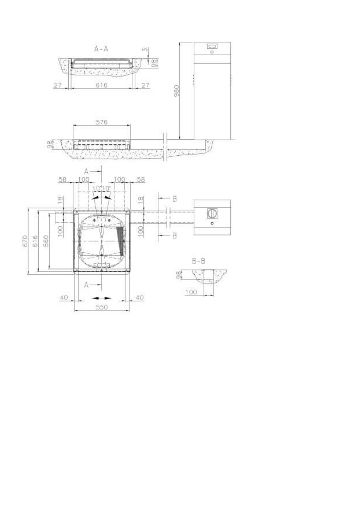
Prepare the recess where set the plates of the play detector and the canal for the connections
(see PLAY DETECTOR DIMENSIONS).
After inspecting the shipment, the play detector can be moved plate by plate by handles, using 2
persons in order to reduce the weight lifted for each of them.
Place platform in the recess.
Place the control box with handlamp and selector + movement pushbuttons to previste distance
from the play detector plate and to prepare to connect to the main central unit.
Take out the electric cables rubber hoses (see to prepare the connection with end bornes in the
control box.
Pass the hydraulic rubber hoses, that you have prepared of the correct length for the installation
(see pictur HOSES LENGTH) from the canal to the central unit. Connecter the hoses to the
electro valve. Make sure all nipless are securely fastened with copper washers.
ICAUTION TAKE CARE OF ELECTRIC CABLES
The personnel assigned to perform these operations should make sure
no extraneous persons are standing in the way of move-
me nt.
2.4. CONNECTION TO POWER MAINS
Before connecting the electric system, make sure that:
the power supply plant is equipped with the protection devices required by current
standards in the country where the machinery is installed.
·the power supply line has the following cross-section:
Voltage 400V, three-phase minimum 1,5 mmq
Voltage 230V, three-phase minimum 1,5 mmq
Voltage 230V, single-phase minimum 2,5 mmq
·the voltage oscillations are within the tolerance range set forth by the specifications.
It is up to the user to ascertain that the power mains comply with international and local
safety standards. The Manufacturer is not responsible for damage due to “Non-Confor-
mity” of the electrical system. The manufacturer will not be liable for any malfunctioning cau-
sed by disturbance from other equipment.
It is essential to make the “EARTH CONNECTION”, using a 0,03A differential switch, and
checking its correct functioning (W) by means of an appropriate measuring device.
2.5. TAKING THE PLAY DETECTOR OUT OF SERVICE
In order to facilitate disposal of the different play detector components, they should be sorted
into categories. Consider the units to be special waste that must be disposed of by specialized
companies in compliance with current regulations.
10

3DESCRIPTION OF THE PLAY DETECTOR
3.1. BEFORE STARTING OPERATION OF THE PLAY DETECTOR
Ensure all hydraulic connections are correct as per hydraulic circuit diagram.
Air bleeding
Energize the right push button end partially open the connection "A" of the Play Detector cylin-
der, until no air bubbles are visible.
Next repeat as above using the left buttom and open connection "B".
Push the selector buttom.
Energize the right push button end partially open the connection "C" of the Play Detector cylin-
der, until no air bubbles are visible.
Next repeat as above using the left buttom and open connection "D".
You are now ready to operate with the play detector.
3.2 OPERATION
Ensure a qualified operator to be the only person within the operating perimeter of the Play De-
tector is clear of park any obstructions.
11

The torch is fitted with 2 push buttons and a selector switch:
- one push button directional left (sliding/rotating plate)
- one push button directional right (sliding/rotating plate)
- the selector switch (sliding or rotating plate)
These push buttons operate solenoid C13 and C14 (see electric scheme)
The selector switch is able to provide sliding or rotating plate selection.
The sequence of operation is in accordance with the current issue of:
THE MOT INSPECTION MANUAL Car and Light Commercial vehicle Testing
Do not perform tests on the motor or do anything else that could apply traction to the wheels.
Do not load any vehicle, exceding the rated working capacity of the Play Detector.
12
RIGHT
LEFT
SELECTOR

4SAFETY DEVICES
The Play Detector has been manufactured in compliance with the provisions issued by “Machine
Directive 2006/42/CE” and all the following harmonized standards
4.1. PRECAUTIONS
For the safety of the operator the following general rules should be adhered to:
·The Play Detector should be under the control of authorized personnel only.
It is important to remember that the sliding plates of the Play Detector are potentially dangerous
for possible crushing, pinching and shearing, of limbs of operators as well as for anyone ne-
arby.
A. Persons working underneath the vehicle, it is essential for the operator to have complete vi-
sibility of the working area.
B. Make sure the vehicles to be tested do not exceed the maximum capacity of the Play Detec-
tor.
Before lifting a vehicle, make sure the front wheels are straight.
The work area should be free of unauthorized personnel.
Do not apply external forces on the raised vehicle (Traction, lifting, etc.)
Check the stability of the vehicle in the raised position before any kind of operation.
4.2. SAFETY DEVICE
The Play Detector has been designed to function with ample safety margins thanks to the devi-
ces provided by the Manufacturer.
Never disconnect the safety devices for any reason. Otherwise the Manufacturer will not
be responsible for any damage to property or persons caused by similar negligence.
The main devices provided are the following:
·Fixed flow limiter (to limit max cylinder speed).
·Mechanical stops at the end of each plate stroke.
·Hydraulic cylinders with overload valve.
·Dead man operation.
13

4.3. TROUBLE SHOOTING TABLE
SYMPTOM POSSIBLE CAUSE REMEDY
Plates are sliding very slowly,
even without load.
Dirt in restrictor screw. Unscrew delivery hose "P"
from the valve block remove
M8 allen screw (with 0.8 mm
hole) clean with cleaning flu-
id and blow out with air gun.
Check pressure of relief
valve.
Platforms are sliding or rota-
ting very slowly, even without
load.
Dirty part into the orifice at
the returning hoses from alu-
minium solenoid block.
Unscrew nipple ¼” from de-
livery hose from aluminuim
block (made in RILSAN pla-
stic). There is inside a small
black screw M8 with an he-
xagonal female key, which
has an orifice diameter 0,8
mm. Check whether this ori-
fice is free or has some dirty
part which create obstacle
to oil flow.
One movement (sliding or ro-
tating) working regularly, the
other doesn’t work at all.
Problem in the handlamp se-
lector. It doesn’t switch on
C11 and C12
Check whether with selector
on handlamp you hear the
“tic” which signals the
on-switching of both C11
and C12. Check connection
on board of solenoid valves,
or into the main connector of
handlamp.
Both plate work in one direc-
tion only.
One pushbutton is broken or
contacts are failing.
Open the handlamp and ve-
rify the pushbutton and its
contacts.
Sliding or rotating plate work
in one direction only.
One of the pushbutton is bro-
ken or contacts are failing.
Remove push button cover
(on torch) and check push
button switches.
14

5MAINTENANCE
Due to the simplicity of construction and operation of the Play Detector, it requires very little ma-
intenance.
It should be sufficient to follow the few simple rules as listed below to ensure reliable performan-
ce.
We strongly recommend for every 6 months operation for the Play Detector to be thoroughly
cleaned, serviced and calibrated, sliders to be replaced as necessary to enhance safe and pro-
longed operation.
Check that other electrical and mechanical parts are in good condition, clean and lubricate as
required.
ICAUTION !
WHILE DISPOSING USED OILS AND LUBRICANTS REFER TO THE
LOCAL RUNNING REGULATION.
5.1. CONTROLS AND CALIBRATION
The following checks must be made every 6 months:
- Check solenoid connectors.
- Check all hydraulic hoses and connections.
- Check all internal electric connections are secured correctly.
- Check for any leaks, etc.
- Check pressure overload device.
15

6ANNEXES – PARTS LIST
WIRING DIAGRAMS AND HYDRAULIC
THREE-PHASE wirning diagram
SINGLE-PHASE wirning diagram
16

HYDRAULIC CIRCUIT DIAGRAM
FC1 Microswitches
FC2 Microswitches
C11 Solenoid valve
C12 Solenoid valve
C13 Solenoid valve
C14 Solenoid valve
17
B
A
C
D
PT
C11
C12
C13
C14

18

19

Part Code Sugg. Description
A0328 “L” MALE CONNECTION G1/4" Ø8
A0346 WASHER 12 X 24 UNI 6592
A0723 SCREW TCEI M8X20 UNI 5931
A1420 SCREW 6X12 8.8 UNI 5739
B0207 * FUSE 5x20 1A
B0794 SCREW TCCE M10X20 UNI 5931 ZB
B2869 * LINE FUSE 10X36 10A aM
B3035 * MAIN SWITCH
B3050 * LINE FUSE 10X36 8A AM
B3051 * MAIN FUSE 10X36 0,5A GG
B3081 1/4" NIPPLES
B3118 * CONTACTOR
B3273 MOTOR 1,1KW 4P C80 B5 230-400/50 3Ph
B3274 MOTOR 1,1KW 4P C80 B5 230/50 1Ph
B3899 COMPLETE ELECTRO-VALVE
B3900 COMPLETE ELECTRO-VALVE
B3914 COMPLETE MANIFOLD
B3933 SLIDE PAD
B3937 SOLENOID VALVE COIL
B3955 COMPLETE HYDRAULIC POWER UNIT 230/400V 50HZ 3PH
B3956 HYDRAULIC POWER UNIT
B3957 MANIFOLD
B3958 SUCTION PIPE
B3960 FILTER
B3963 OIL DELIVERY HOSE
B3964 ELECTRIC WIRES KIT
B3969 MANIFOLD SUPPORT
B3984 SCREW M8X8 UNI 5923 WITH HOLE Ø0,8
B4019 COMPLETE HANDLAMP
B4052 OIL FILTER
B4065 * ELECTRIC CABLE
B4072 COMPLETE HYDRAULIC POWER UNIT 230V 50HZ 1PH
B4077 * GLASS WITH LEDS
B4078 LAMP BOARD
B4221XX CABINET
B4222XX ELECTRICAL BOARD BOX
B4223XX DOOR
B4224XX DOOR
B4227XX COVER
B4278 * TORCH RED SELECTOR
B4279 * TORCH BLACK BUTTOM
B5028 * BUSHING Ø40X44X30MBI CB85 402
B5034 SCREW M8X12 UNI 5933
B5047 GASKET WITH 1/4" SEAL
B5049 EXTENSION
20
Table of contents