Wesco 272973 User manual

Page1of11
TABLE OF CONTENTS
1 General Information ............................................................................................................... 2
1.1 Description.....................................................................................................................2
1.2 Specifications.................................................................................................................2
2 Safety Information.....................................................................................................................2
3 Daily Inspection…................................................................................................................... 3
4 Operation.................................................................................................................................. 3
4.1 Braking............................................................................................................................3
4.2 Lifting.............................................................................................................................. 3
4.3 Lowering......................................................................................................................... 3
5 Maintenance..............................................................................................................................3
6 272970 Part Information............................................................................................................4
6.1 272970 Frame Diagram..................................................................................................4
6.2 272970 Frame Part List.................................................................................................. 5
6.3 272970 Pump Diagram...................................................................................................6
6.4 272970 Pump Part List................................................................................................... 7
7 272973 Part Information............................................................................................................8
7.1 272973 Frame Diagram..................................................................................................8
7.2 272973 Frame Part List.................................................................................................. 9
7.3 272973 Pump Diagram...................................................................................................10
7.4 272973 Pump Part List................................................................................................... 11
WESCOINDUSTRIALPRODUCTS,INC
InstructionManual
HeavyDutyScissorsLiftTables
PartNumber: 272970&272973
Note: Operator MUST read and understand these operating instructions before using
this Heavy Duty Scissors Lift Table.

Page2of11
Heavy Duty Scissors Lift Tables
(Part # 272970 & 272973)
Instruction Manual
ATTENTION: TO INSURE SAFE AND EASY USE OF YOUR SCISSORS LIFT TABLE,
READ THESE INSTRUCTIONS ENTIRELY BEFORE USING.
1. GENERAL INFORMATION
1.1 DESCRIPTION
Thank you for purchasing a Heavy Duty Scissor Lift Table. These tables feature a fixed,
chrome plated lever release handle, a foot operated pump and locking swivel casters.
1.2 SPECIFICATIONS
Part Number 272970 272973
Model LT-1650-SL LT-2200SL
Capacity 1650 lbs 2200 lbs
Table Size 20” x 39” 20” x 40”
Table Thickness .1” .12”
Raised Height 35.5” 39”
Lowered Height 16.5” 15”
Caster Size 5” x 2” 5” x 2”
Locking Caster Yes Yes
Weight 276 lbs 269 lbs
Materials and specifications are subject to change without notice.
2. SAFETY INFORMATION
1) Read this operation manual carefully and understand completely operating procedures for this lift
table.
2) This lift table is a movable lifter designed to lift or lower rated loads on table. DO NOT use the lift
table for uses other than its intended use.
3) Do not put feet or hands in scissors mechanism.
4) Do not move lift table when table is in raised position.
5) Do not position yourself under the table.
6) Do not overload the lift table.
7) Do not use lift table on sloped or inclined surface, the lift table may become unstable.
8) Do not lift people.
9) Do not lower table too rapidly.
10) Do not place loads on the side or end of table. A load must be distributed on at least 80% of table
area.
11) Do not use the lift table with unstable, unbalanced load.
12) Do not modify the lift table without manufacturer’s written consent.
13) Use swivel locks to prevent the table from lowering when loading, unloading or servicing it.

Page3of11
Heavy Duty Scissors Lift Tables
(Part # 272970 & 272973)
Instruction Manual
ATTENTION: TO INSURE SAFE AND EASY USE OF YOUR SCISSORS LIFT TABLE,
READ THESE INSTRUCTIONS ENTIRELY BEFORE USING.
3. DAILY INSPECTION
Daily inspection is effective to find any malfunction or fault on the lift table. Check the lift table for the
following before operation:
1) Check for any scratches, bending or cracking on the lift table.
2) Check if there is any oil leakage from the cylinder.
3) Check the vertical creep of the table.
4) Check the smooth movement of the wheels.
5) Check the brake.
6) Check all bolts and nuts are tightened firmly.
CAUTION: Do not use lift table if any malfunction or fault is found.
4. OPERATION
4.1 Braking
CAUTION: Lift the brake when not moving it in order to prevent sudden movement.
The brake is equipped with the swivel caster on the right side.
1) Brake the wheel by pressing the brake pedal.
2) Release the brake by lifting up the brake pedal.
4.2 Lifting
Warning
1) Do not overload lift table. Stay within its rated capacity.
2) Do not side or end. Load must be distributed on at least 80% of table area.
Press the lifting pedal several times until the table reaches the desired position. The table does not
elevate after reaching the highest position even if the lifting pedal is pressed. The table lowers slightly
after reaching the highest position.
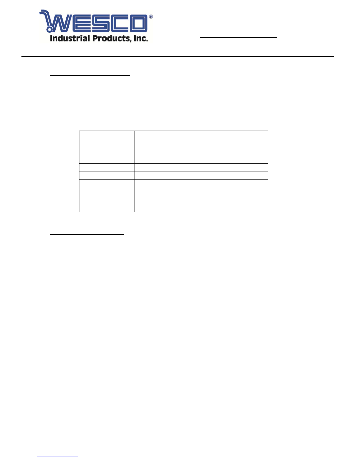
Model LT-1650SL LT-2200SL
Part Number 272970 272973
Max Capacity (lbs) 1,650 2,200
Note: The hydraulic cylinder is designed to hold the table. The nature of hydraulic systems cause the
table to lower very slowly over an extended period of time. Please note the table does not stay at the
same position indefinitely.
4.3 Lowering
Warning: Do not put foot or hand in scissors mechanism
1) Rotating the knob lowers the table.
5. MAINTENANCE
5.1 Lubricate each point described below every month
5.2 Change hydraulic oil every 12 months.
Lubricating Points
1) Fitting of Cylinder – Oil
2) Roller Friction Surface – Grease
3) Link Pin – Oil
4) Pedal Fitting Point – Oil
5) Grease Nipple - Grease

Page4of11
Heavy Duty Scissors Lift Tables
(Part # 272970 & 272973)
Instruction Manual
ATTENTION: TO INSURE SAFE AND EASY USE OF YOUR SCISSORS LIFT TABLE,
READ THESE INSTRUCTIONS ENTIRELY BEFORE USING.
6. 272970 PART INFORMATION
6.1 272970 FRAME DIAGRAM

Page5of11
Heavy Duty Scissors Lift Tables
(Part # 272970 & 272973)
Instruction Manual
ATTENTION: TO INSURE SAFE AND EASY USE OF YOUR SCISSORS LIFT TABLE,
READ THESE INSTRUCTIONS ENTIRELY BEFORE USING.
6. 272970 PART INFORMATION
6.2 272970 FRAME PART LIST
Item P/N Item Description Qty. Item P/N Item Description Qty.
101M 260261 Handle Grip 1 134 Bolt 1
102 Kit:
Handle
Release
Assembly
260253
Control Handle 1 135 Shaft 1
103 Elastic Pin 1
136 Retaining Ring 1
104 Nut 1
137 Axle of Wheel 1
105 Bolt with Hole 1
138G Pump Unit 1
106 Jacket 1
139 260265 Pin 1
107 Pull Line 1
140 260266 Roller 1
108 Elastic Pin 1
141 260267 Retaining Ring 1
109 Shaft 1
142 Pin 1
110 Cam 2
143 Washer 1
111 Pedal 1
144 Retaining Ring 1
112 Screw 3
145 260268 Connecting Rod 1
113 Nut 3
146 Cushion 1
114 260262 Big Washer 2 147 Bolt 1
115 260263 Elastic Washer 2 148 Washer 1
116 260264 Bolt 2 149 Elastic Washer 1
117 Bolt 2
150 Nut 1
118 Nut 2
151 Protecting Nut 1
119 Round Nut 4
152 Pedal Bar 1
120 Spring 2
153 Retaining Ring 1
121
Kit:
Caster
Assembly
260256
Seat of Wheel 2 154 Roller 1
122 Bolt 2
155 Roller 1
123 Brake 2
156 Table 1
124 Washer 4
157 Retaining Ring 1
125 Bearing 8
158 Shaft 1
126 Wheel 4
159 Fork Arm 1
127 Axle 2
160 Elastic Washer 1
128 Elastic Washer 2
161 Screw 1
129 Nut 2
162 Screw 1
130 Bearing 2
163 Nut 1
131 Washer 2
164 Support Plank 1
132 Bearing 2
165 Elastic Pin 1
133 Frame 1
REPLACEMENT KITS OFFERED
260253 Handle Release Assembly (Includes items 102-107) 1
260256 Caster Assembly (Includes Items 121-129) 2
260257 Wheel Assembly (Includes 2 of Item 125 & 1 of Item 126) 2

Page6of11
Heavy Duty Scissors Lift Tables
(Part # 272970 & 272973)
Instruction Manual
ATTENTION: TO INSURE SAFE AND EASY USE OF YOUR SCISSORS LIFT TABLE,
READ THESE INSTRUCTIONS ENTIRELY BEFORE USING.
6. 272970 PART INFORMATION
6.3 272970 PUMP PART DIAGRAM

Page7of11
Heavy Duty Scissors Lift Tables
(Part # 272970 & 272973)
Instruction Manual
ATTENTION: TO INSURE SAFE AND EASY USE OF YOUR SCISSORS LIFT TABLE,
READ THESE INSTRUCTIONS ENTIRELY BEFORE USING.
6. 272970 PART INFORMATION
6.4 272970 PUMP PART LIST
Item P/N Item Description Qty. Item P/N Item Description Qty.
201 Seal Washer 1
230 Spring 1
202 Pump Cylinder 1
231 Spindle of Safety Valve 1
203 Dust Ring 1
232 Steel Ball 1
204 Y-Seal 1
233 O-Ring 1
205 Pump Piston 1
234 Seat of Pumping Valve 1
206 Spring 1
235 Spindle of Pumping Valve 1
207 Spring Cap 1
236 Spring 1
208 Retaining Ring 1
237 Seal Washer 1
209B Joint Plate 2
238B O-Ring 1
210 Pin 1
239G Seal Washer 1
211G Pump Body 1
240G Cylinder 1
212 Elastic Pin 1
241B Housing 1
213 Spring 1
242 Bolt 1
214B Strike pin 1
243 Seal Washer 1
215 Seal Washer 1
244 Retaining Ring 1
216B Axle Sleeve 1
245G Washer 1
217 O-Ring 2
246G Y-Seal 1
218 Nut 1
247 1
219 Screw 1
248G Piston 1
220 Lever Plate 1
249G O-Ring 1
221 Nut 1
250G Piston Rod 1
222 Elastic Washer 1
251B O-Ring 1
223 Washer 1
252G Cylinder Cap 1
224 Bolt with Hole 1
253G O-Ring 1
225 Bolt with Hole 1
254G Dust Ring 1
226 Nut 1
255B Plug 1
227 Plug 1
256 Liquid Throttle 1
228 O-Ring 1
257 Bolt 1
229 Adjusting Bolt 1
258B O-Ring 2

Page8of11
Heavy Duty Scissors Lift Tables
(Part # 272970 & 272973)
Instruction Manual
ATTENTION: TO INSURE SAFE AND EASY USE OF YOUR SCISSORS LIFT TABLE,
READ THESE INSTRUCTIONS ENTIRELY BEFORE USING.
7. 272973 PART INFORMATION
7.1 272973 FRAME DIAGRAM

Page9of11
Heavy Duty Scissors Lift Tables
(Part # 272970 & 272973)
Instruction Manual
ATTENTION: TO INSURE SAFE AND EASY USE OF YOUR SCISSORS LIFT TABLE,
READ THESE INSTRUCTIONS ENTIRELY BEFORE USING.
7. 272973 PART INFORMATION
7.2 272973 FRAME PART LIST
Item P/N Item Description Qty. Item P/N Item Description Qty.
101M Handle Grip 1
135 Shaft 1
102 Control Handle 1
136 Retaining Ring 1
103 Elastic Pin 1
137 Axle of Wheel 1
104 Nut 1
138G Pump Unit 1
105 Bolt with Hole 1
139 Pin 1
106 Jacket 1
140 Roller 1
107 Pull Rod 1
141 Retaining Ring 1
108 Elastic Pin 1
142 Pin 1
109 Shaft 1
143 Washer 1
110 Cam 1
144 Retaining Ring 1
111 Pedal 1
145G Connecting Rod 1
112 Screw 1
146 Cushion 1
113 Nut 1
147 Bolt 1
114 Big Washer 1
148 Washer 1
115 Elastic Washer 1
149 Elastic Washer 1
116 Bolt 1
150 Nut 1
117 Bolt 1
151 Protecting Cover 1
118 Nut 1
152 Pedal Bar 1
119 Round Nut 1
153 Retaining Ring 1
120 Spring 1
154 Roller 1
121G Seat of Wheel 1 155 Roller 1
122 Bolt 1
156G Table 1
123G Brake 1
157 Retaining Ring 1
124 Washer 1
158 Shaft 1
125 Bearing 1
159G Fork Arm 1
126G Wheel 1
160 Elastic Washer 1
127 Axle 1
161 Screw 1
128 Elastic Washer 1
162 Nut 1
129 Nut 1
163 Screw 1
130 Bearing 1
164 Support Plank 1
131 Washer 1
165 Elastic Pin 1
132 Bearing 1
166 Protecting Board 1
133G Frame 1
167 Bolt 1
134 Bolt 1
168 Bushing 1

Page10of11
Heavy Duty Scissors Lift Tables
(Part # 272970 & 272973)
Instruction Manual
ATTENTION: TO INSURE SAFE AND EASY USE OF YOUR SCISSORS LIFT TABLE,
READ THESE INSTRUCTIONS ENTIRELY BEFORE USING.
7. 272973 PART INFORMATION
7.3 272973 PUMP DIAGRAM

Page11of11
Heavy Duty Scissors Lift Tables
(Part # 272970 & 272973)
Instruction Manual
ATTENTION: TO INSURE SAFE AND EASY USE OF YOUR SCISSORS LIFT TABLE,
READ THESE INSTRUCTIONS ENTIRELY BEFORE USING.
7. 272973 PART INFORMATION
7.4 272973 PUMP PART LIST
Item P/N Item Description Qty. Item P/N Item Description Qty.
273632 Complete Pump Replacement 1
230 Spring 1
201 Seal Washer 1
231 Spindle of Safety Valve 1
202 Pump Cylinder 1
232 Steel Ball 1
203 Dust Ring 1
233 O-Ring 1
204 Y-Seal 1
234 Seat of Pumping Valve 1
205 Pump Piston 1
235 Spindle of Pumping Valve 1
206 Spring 1
236 Spring 1
207 Spring Cap 1
237 Seal Washer 1
208 Retaining Ring 1
238B O-Ring 1
209B Joint Plate 2
239G Seal Washer 1
210 Pin 1
240G Cylinder 1
211G Pump Body 1
241B Housing 1
212 Elastic Pin 1
242 Bolt 1
213 Spring 1
243 Seal Washer 1
214B Strike pin 1
244 Retaining Ring 1
215 Seal Washer 1
245G Washer 1
216B Axle Sleeve 1
246G Y-Seal 1
217 O-Ring 2
247 1
218 Nut 1
248G Piston 1
219 Screw 1
249G O-Ring 1
220 Lever Plate 1
250G Piston Rod 1
221 Nut 1
251B O-Ring 1
222 Elastic Washer 1
252G Cylinder Cap 1
223 Washer 1
253G O-Ring 1
224 Bolt with Hole 1
254G Dust Ring 1
225 Bolt with Hole 1
255B Plug 1
226 Nut 1
256 Liquid Throttle 1
227 Plug 1
257 Bolt 1
228 O-Ring 1
258B O-Ring 2
229 Adjusting Bolt 1
This manual suits for next models
1
Table of contents
Other Wesco Scissor Lift manuals
Popular Scissor Lift manuals by other brands

WERTHER INTERNATIONAL
WERTHER INTERNATIONAL SATURNUS 50R Original instructions

POP UP
POP UP IQ LIFT PRO10 OPERATIONS & SAFETY HANDBOOK

TLS
TLS TLSS14ALOR installation manual

EAE
EAE EE-6605S Installation, operation, and parts manual

Mec
Mec 2047ES Service and parts manual

Upright
Upright MX Series Service and maintenance manual