159131G
LIMITED WARRANTY
WESCO INDUSTRIAL PRODUCTS (WESCO) warrants to the purchaser of this product for a period of ninety (90) days from the date of purchase that this product shall be free of
defects in material and/or workmanship, as follows:
1. WESCO will supply, at no charge, new or rebuilt replacements for any part that fails through a defect in material and/or workmanship during the warranty period. To obtain warranty
service, you must deliver the product prepaid, to the WESCO factory.
2. This warranty does not cover any product or product part which has been subject to accident, misuse, abuse or negligence. WESCO shall only be liable under this warranty if the
product is used the manner intended by the manufacturer as specified in the written instructions furnished with this product.
REPAIR OR REPLACEMENT AS PROVIDED UNDER THIS WARRANTY IS THE EXCLUSIVE REMEDY OF THE PURCHASER. ANY EXPRESS WARRANTY NOT PROVIDED IN
THIS WARRANTY DOCUMENT, AND ANY REMEDY FOR BREACH OF CONTRACT THAT, BUT FOR THIS PROVISION, MIGHT ARISE BY IMPLICATION OR OPERATION OF LAW,
IS HEREBY EXCLUDED AND DISCLAIMED. UNDER NO CIRCUMSTANCES SHALL WESCO BE LIABLE TO PURCHASER OR ANY OTHER PERSON FOR ANY INCIDENTAL OR
CONSEQUENTIAL DAMAGES, WHETHER ARISING OUT OF BREACH OF WARRANTY, EXPRESS OR IMPLIED, A BREACH OF CONTRACT OR OTHERWISE. EXCEPT TO THE
EXTENT PROHIBITED BY APPLICABLE LAW, ANY IMPLIED WARRANTY OF MERCHANTABILITY AND FITNESS FOR ANY PARTICULAR PURPOSE ARE EXPRESSLY LIMITED
IN DURATION TO THE DURATION OF THIS LIMITED WARRANTY.
Some states do not allow the exclusion or limitation of incidental or consequential damages, or allow limitations on how long any implied warranty lasts, so the above limitations may not
apply to you. This warranty gives you specific legal rights, and you may also have other rights which vary from state to state.
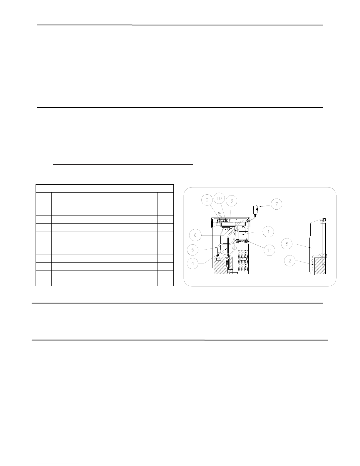
Ergonomic Drum Handler DM-1100
Operating Instructions and Parts Manual
Description
The Wesco Ergonomic Drum Handler DM-1100s are
designed specifically for lifting and transporting 30, 55 and 85
gallon steel, fiber and poly drums.
This product is distributed by:
Wesco Industrial Products, Inc
1250 Welsh Road
North Wales, PA 19454
Tel: 215-699-7031 Fax: 215-699-3836
Contact the factory for parts information and ordering.
Visit us on the web at www.wescomfg.com
Unpacking
When unpacking the Wesco Product, check carefully for
shipping damage and missing parts. If damage has occurred
or any parts are missing, file a claim with the delivering carrier
within 24 hours and notify the dealer from whom the unit was
purchased. Warranty Repairs
If the unit does not work properly, contact your dealer or the
factory (215-699-7031) for units less than 90 days old.
Non-Warranty Service
If units are older than 90 days, repairs can be made easily on
site with factory supplied parts.
NOTE: Do not send units to the factory for service without
first obtaining a “Return Merchandise Authorization” (RMA)
number from the customer service department. We will not
be responsible for merchandise returned without proper
authorization. General Safety Information
The Wesco Model DM1100 is designed for specific functions.
To insure proper use, the following instructions must be
adhered to:
(1) Load Rating: 1100 lbs./(legs extended) 650 lbs./(legs
retracted)
(2) DO NOT use unit for loads exceeding the rated capacity.
(3) This product is designed for use on level floors only. DO
NOT use unit, or engage floor lock, on any incline
greater than five (5) degrees.
General Safety Information (cont’d)
(4) Keep hands and feet clear of clamping head, mast and
wheels.
(5) Clamping head must be in full contact with drum rim
prior to lifting.
(6) Be certain rim of fiber or plastic drum is able to withstand
the stress of drum lifting procedure.
(7) Be certain that both ends of lift chain are securely
fastened to jack and chain anchor before lifting load.
(8) DO NOT transport load at maximum height. Transport
drum 2 to 3 inches off floor.
(9) Use extreme care when travelling over uneven floors.
(10) DO NOT use on ramps
(11) DO NOT modify this product in any way.
(12) Periodically inspect for damage, and loose or missing
hardware. If required remove unit from service
Operation Instructions
(1) Move unit towards drum until the clamping head firmly
contacts the sidewall of the drum.
Note: Three sets of holes in the top of the mast allow for
the adjustment of the clamping head to grab a drum.
(2) Raise the mast above the frame upright until the lowest
adjustment hole clears the mast. While holding the
clamping head and slides with one hand, insert the
adjustment pin through the appropriate set of holes to
obtain the proper height for grabbing a drum
(3) Engage the floor lock (if present) and raise the drum 2” to
3” off of the floor by stepping on the pumping pedal or
using the power lift.
Note: If a drum is to be moved from a raised platform,
engage the clamping head against the drum, raise the
load to clear the platform, and lower the drum to the
recommended height for transportation
(4) Disengage the floor lock (if present), and transport drum
to the desired location.
(5) Engage floor lock (if present), and lower drum to floor by
pressing relief pedal located on left side of hydraulic jack
or using the power lift.
Note: If drum is to be positioned on a raised platform,
raise the drum so that it clears the platform, move the
load to the required position, and lower the drum.
Industrial Products, Inc. ATTENTION: TO INSURE SAFE AND EASY USE OF YOUR WESCO DRUM
HANDLER, READ THESE INSTRUCTIONS BEFORE USING.
Industrial Products, Inc.