West Mountain Radio ISOpwr User manual

www.westmountainradio.com
1020 Spring City Drive
Waukesha, WI 53186
262-522-6503
©2012 West Mountain Radio, All rights reserved. All trademarks are
the property of their respective owners.
ISOpwr

2
West Mountain Radio Operating Manual
Thank you for choosing the West Mountain Radio ISOpwr. It isolates an auxiliary
battery while also supplying power to the battery.
The ISOpwr is an automotive ON-OFF switch that will charge an auxiliary
battery and run mobile radio equipment. The ISOpwr turns ON when the car is
running and the alternator is over 13.5 volts. The ISOpwr turns OFF when the
alternator is not running and the car’s battery has fallen below 12.6 volts.
Equipment connected to the ISOpwr will be powered from the auxiliary battery.
When the car is running the equipment is also powered by the car’s alternator.
Note: The car’s battery will never be drained by leaving the
equipment turned on. The car will always start.
The ISOpwr is ideal for use in all vehicles utilizing an auxiliary battery for diverse
purposes such as a radio command set up for ARES, RACES, FEMA, contest
VHF/UHF rover, moderately powered ham equipment, a re-charging station for
electric model airplanes, boats and cars, and for RV’s and campers.
The ISOpwr may be used without a battery to automatically turn a radio on
whenever the car is running. The radio will turn off with a short delay after the
car is stopped.
Installation
The ISOpwr connects between the automotive 12-volt system and the auxiliary
battery. The auxiliary battery and the equipment are usually located in the car’s
trunk. Place the ISOpwr unit close to the battery and equipment. Then run the
cable to the car’s battery.
Note: The ISOpwr should be mounted in a dry location.
It is not waterproof.
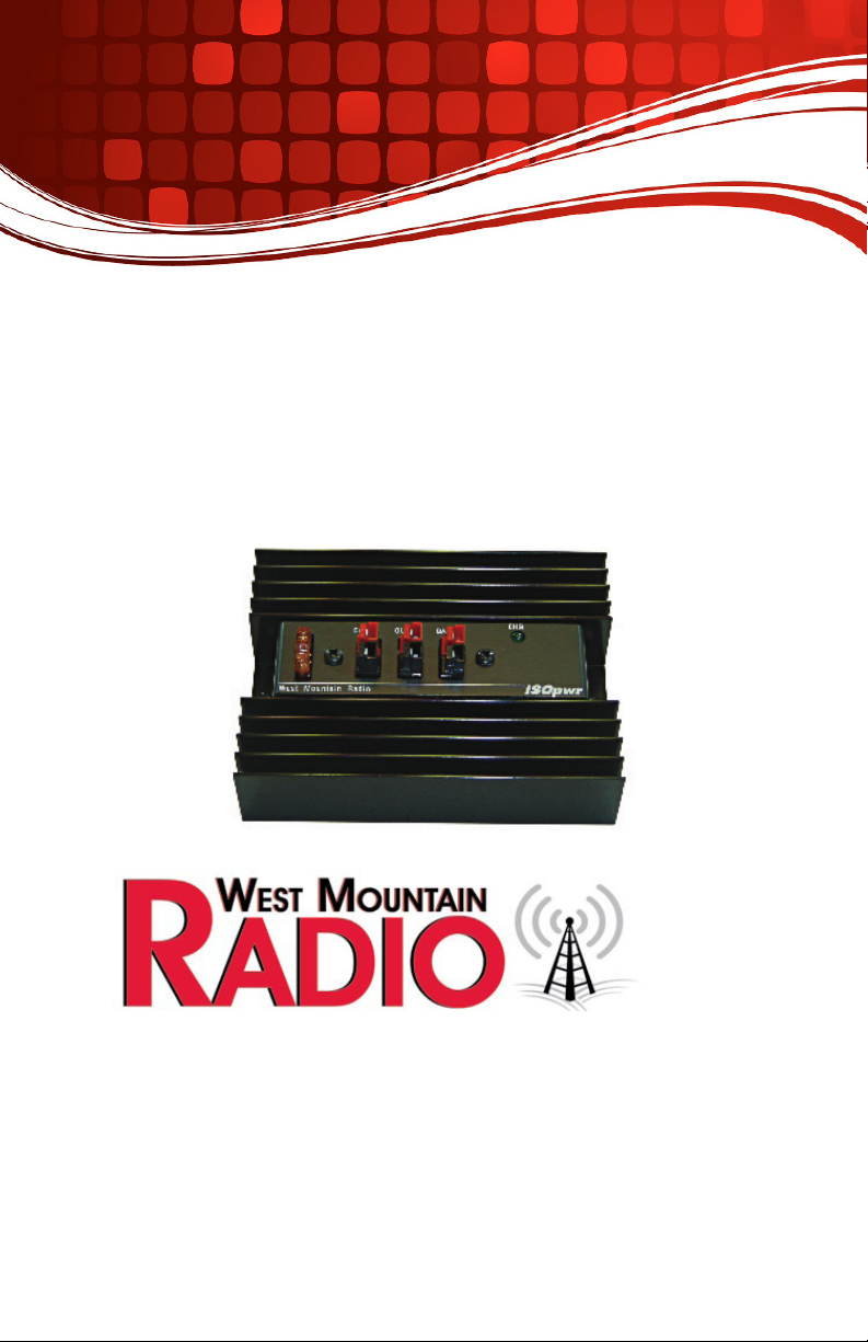
The unit is equipped with Anderson Powerpoles. Input (CAR) is on the left
side and this connects to the vehicle 12-volt battery; the auxiliary battery (BAT)
connects to the right Powerpole; and the equipment (OUT) connects to the
center Powerpole. If needing to power multiple devices, it is suggested to install
a RIGrunner distribution panel and connect it to the ISOpwr output.
It is recommended to use #10 AWG wire when connecting up 12 volt, 100 watt,
radio equipment. If #12 AWG wire is used, keep the lengths short.
Be sure to connect the RED Powerpole connects to the RED wire and
connect to the PLUS terminal. Similarly, make sure that the BLACK
Powerpole connect to the BLACK wire and connect to the NEGATIVE
terminal.

3
West Mountain Radio Operating Manual
Safety Precautions
Auxiliary Battery Choices:
1. When using an automotive battery, it should be mounted in the trunk or un-
der the hood. Do not place it in the passenger area of the vehicle. These
unsealed batteries will emit gases that are dangerous in a closed area.
2. If using a sealed lead acid battery, it can be placed internally. The AGM,
glass mat type is a good choice. It has a charging voltage that is similar to
the car’s alternator voltages.
3. If using a GEL type battery, it also can be placed internally. However, con-
rm that the alternator voltage does not exceed 14.5 volts (at 70 degrees F).
This will ensure full life for the GEL cell.
Fuses
A fuse must be placed in the wire at the battery terminals connecting to the car’s
battery. A 40 ampere fuse is recommended. This safety precaution is neces-
sary because the battery is a large power-storage device that, if shorted, would
release a massive amount of energy, sometimes causing the battery to explode.
ISOpwr Installation Checks
After installation, verify the ISOpwr for proper operation.
1. With the engine OFF, make sure the ISOpwr green LED is off.
2. Start the engine. After a few seconds the Green LED will illuminate showing
the car is now connected to the auxiliary battery and/or the radio equipment.
Make sure that the radio also turns on.
3. Turn off the engine. The green LED will stay on for a while because the
car’s battery may be above 12.6 volts. After a few minutes the car’s battery
will have dropped to less than 12.6 volts and the ISOpwr will turn off.
Note: To rapidly drop the car’s battery, switch on the car headlights.

4
West Mountain Radio Operating Manual
ISOpwr Operation with Auxiliary Battery
The ISOpwr output (OUT) and the auxiliary battery (BAT) are internally con-
nected together. Therefore, equipment connected to the ISOpwr output is
powered directly from the auxiliary battery.
When the car is running, the ISOpwr Green LED will illuminate indicating that
the auxiliary battery is being charged by the car’s alternator. Equipment con-
nected to the ISOpwr will also be powered by the car’s alternator.
When the car is OFF, the ISOpwr LED will go out after a short period of time.
Note: The current supplied by the car’s alternator is shared between the
car’s battery and the auxiliary battery, according to the load and
the various voltages
ISOpwr Operation without Auxiliary Battery
The ISOpwr may be used without a battery. It will automatically turn ON and
apply the car’s charging voltage to any load whenever the car is running. It will
turn OFF with a small delay after the car is no longer running. This is useful to
prevent items from discharging the car’s battery when they are inadvertently
left on.
To use without an auxiliary battery, connect the ISOpwr input (CAR) to the
car’s battery. Then plug the radio (or any other item) into the ISOpwr output
(OUT). The radio will be powered whenever the car is running.
Many times a radio is left turned on in a vehicle. However, with the ISOpwr, it
will automatically turn off thereby preventing a drained car battery.
Technical Description
The ISOpwr is a voltage-controlled switch connected to the 12-volt source.
The circuit consists of a power MOSFET with a high side driver, a voltage
comparator circuit, and a power diode.
The MOSFET is basically a variable resistor functioning as a switch. Its resis-
tance is less than 10 milliohms in the ON mode, and many megohms in the
OFF mode. The MOSFET is kept cool by conducting heat to the heatsink.
Note: The device contains a high-side driver that also protects
the FET. It turns off if the temperature rises too high and
if the current exceeds 100 amperes, (i.e. a shorted out-
put.) The MOSFET is rated to handle more than 40 amperes.

5
West Mountain Radio Operating Manual
The voltage comparator senses the ISOpwr’s input voltage. If the voltage
is above 13.4 volts it switches the MOSFET ON. When the MOSFET is on,
the comparator changes the reference so the input voltage now must fall to
below 12.6 before the MOSFET goes back to OFF. (This “hysteresis” system
prevents the ISOpwr from going on and off during load variations.)
There is an 80-ampere Schottky diode in series with the output. This pre-
vents any reverse voltage problems as well as providing a 0.25 volt drop to
prevent overcharging the auxiliary battery from a non-precise alternator.
Note: A battery’s quiescent voltage is between 12.0 and 12.2
volts. When the alternator is charging, the applied vol-
tage varies from 13.8 to 14.4 depending upon the current
being supplied. Therefore, the ISOpwr connects the batter-
ies together when the alternator is operating, and isolates
the vehicles battery when the car’s system has returned to
the car’s battery only.
The Green LED is connected to the MOSFET’s output. It is lighted whenever
the MOSFET is on. It does not measure charging current.
A 40 ampere fuse is in series with the ISOpwr input. The fuse may be
changed to a smaller value if needed.
Specications
Operating Voltage: 20 V maximum
Quiescent Current: Less than 5 mA
Maximum Current: 40 A
Voltage Drop: 0.25 V at 1A, diode drop
Series Resistance: 0.01 ohms maximum
Switch Time-Constant: 5 seconds
Turn ON Threshold: 13.3 (+/- 0.1)V
Turn OFF Threshold: 12.6 (+/- 0.1)V
Green LED: Indicates the ISOpwr output is ON
Size: 5.25 x 3.95 x 1.65 in, 13.4 x 9.9 x 4.2 cm
Weight: 0.9 lbs, 0.4 kg
Enclosure: Heatsink, black anodized aluminum.
Painted aluminum cover

ISOpwr Warranty
ISOpwr is warranted against failure due to defects in workmanship or materials for one
year after the date of purchase from West Mountain Radio. Warranty does not cover
damage caused by abuse, accident, misuse, improper or abnormal usage, failure to follow
instructions, improper installation, alteration, lightning, or other incidence of excessive
voltage or current. If failure occurs within this period, return the ISOpwror accessory to
West Mountain Radio at your shipping expense. The device or accessory will be repaired
or replaced, at our option, without charge, and returned to you at our shipping expense.
Repaired or replaced items are warranted for the remainder of the original warranty period.
You will be charged for repair or replacement of the ISOpwr or accessory made after the
expiration of the warranty period.
West Mountain Radio shall have no liability or responsibility to customer or any other person
or entity with respect to any liability, loss, or damage caused directly or indirectly by use
or performance of the products or arising out of any breach of this warranty, including,
but not limited to, any damages resulting from inconvenience, loss of time, data, property,
revenue, or profit, or any indirect, special incidental, or consequential damages, even if
West Mountain Radio has been advised of such damages.
Except as provided herein, West Mountain Radio makes no express warranties and any
implied warranties, including fitness for a particular purpose, are limited in duration to the
stated duration provided herein.
www.westmountainradio.com
1020 Spring City Drive, Waukesha, WI 53186
tel 262-522-6503 fax 262-522-6504
Table of contents
Other West Mountain Radio Switch manuals
Popular Switch manuals by other brands

StarTech.com
StarTech.com ICUSB2324I instruction manual

D-Link
D-Link DUB-2340 Quick installation guide

Enterasys
Enterasys BL-89420ENT user guide

Disaster Area Designs
Disaster Area Designs DPC.micro user manual

NOCH
NOCH 60264 instruction manual

Hisselektronik
Hisselektronik Safeline 2000 Light Manual for Programmering