West Pond Enterprises MX-400HY User manual

MX-400HY Installation & Operations
Manual
Software Revision 1.16.5
West Pond Enterprises, LLC
5/16/2018

Confidential Page 1
Contents
Revision History ............................................................................................................................................3
Related documentation ................................................................................................................................3
Terms and terminology................................................................................................................................. 3
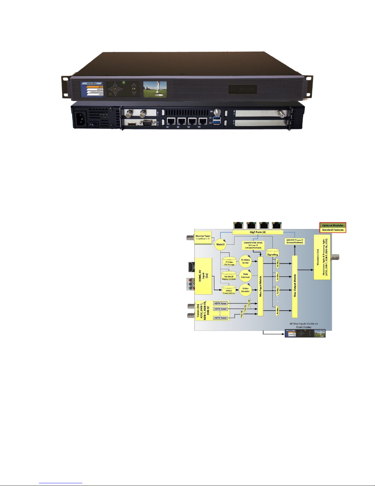
MX-400HY .....................................................................................................................................................3
MX-400HY Hardware ................................................................................................................................5
MX-400HY Software.................................................................................................................................. 5
Setting up the system ................................................................................................................................... 5
Unpacking the unit.................................................................................................................................... 5
Installing in the rack..................................................................................................................................6
Making the connections............................................................................................................................6
Power On .................................................................................................................................................. 6
Configuring the system .................................................................................................................................7
Front panel................................................................................................................................................ 7
Accessing the WebUI ................................................................................................................................ 8
Getting familiar with the MX-400 .................................................................................................................8
Overview ...................................................................................................................................................9
Sources......................................................................................................................................................9
Network Sources.................................................................................................................................10
Tuners .................................................................................................................................................10
Video Server........................................................................................................................................10
Video Wrapper....................................................................................................................................11
Outputs ...................................................................................................................................................14
MDx00................................................................................................................................................. 15
Program Mapping ...............................................................................................................................15
Oversubscribing the Transport ...........................................................................................................16
Display Controls ......................................................................................................................................17
Monitor ...................................................................................................................................................17
System..................................................................................................................................................... 18
Settings................................................................................................................................................18
Accounts.............................................................................................................................................. 19
Log.......................................................................................................................................................19

Confidential Page 2
Info ......................................................................................................................................................19
Tools.................................................................................................................................................... 20
Appendix A –Quick Start Help....................................................................................................................21

Confidential Page 3
Revision History
Date
Version
By
Description
7/20/2017
1.0.2
sdh
Created for version 1.0.2 of the software
11/29/2017
1.10.0
sdh
Time to update…. Bring to latest software revision
5/1/2018
1.16.4
sdh
Thumbnails, Scanning, etc.
5/17/2018
1.16.5
sdh
Small edits to typos. Bump SW version.
Related documentation
Date
Version
By
Description
NA
1.15.1
sdh
User Guide, FlexStream MX-GS200, MD-100, RX-WP100
NA
NA
NA
Flexstream U-Tube channel.
https://www.youtube.com/channel/UCsZyIiqtSbF18sTyioOjS5Q
Terms and terminology
TS
MPEG2 Transport Stream
MPTS
Multi-program Transport Stream
Inputs
Physical inputs to the MX-400
Sources
TS traffic entering the multiplexor
Outputs
TS traffic exiting the multiplexor
Targets
Output devices receiving TS traffic from the multiplexor
Video Server
Feature of the MX-400 software that creates live program streams (TV
channels) from 1 or more TS files via a loop or scheduled event.
Video Wrapper
Feature of the MX-400 software that wraps video Inputs with HTML5
graphical content and then encodes it to make a program stream.
Monitor
Feature of the MX-400 software, included with the RF modulator, which
scans the target RF plant for unused frequencies and monitoring used
frequencies.
Note: “MX-400”and “MX-400HY”are uses interchangeably in this document.
MX-400HY
Thank you for purchasing the MX-400HY digital video media system. This product was specifically
designed to enhance the value of TV networks in hotels, hospitals, schools and other institutions that
utilize linear TV such as COAX and IPTV. Using the existing coax infrastructure, or traditional IPTV, the
MX-400HY enables reception and redistribution of broadcast TV channels, HDMI video capture TV
channels, RTSP security camera TV channels, multi-media advertisement, and venue wide display
controls. This document will help you get the MX-400HY up and running quickly. For your convenience
a quick start section is provide at the end of this document. See Appendix A –Quick Start Help. For
more information please contact West Pond Enterprises sales or support.

Confidential Page 4
The single system provides features that normally require a collection of rack mounted equipment, set
top boxes, and media servers. Integrating these components together not only reduces the cost and
space required to host the system, it enables advanced features and simplifies overall operation. A
single UI allows you to manage the entire system. Here’s a list of standard equipment the MX-400HY
replaces.
Video Server / Streamer
oLoad up to 30 hours of video files onto the MX-400HY and create custom TV channels
via our built in video server. Create a looping playlist or schedule playback at specific
times.
Video Encoder - HDMI / Component / Composite
oCapture video and audio from any of these ports and encoded it to broadcast quality
standards. This box supports h.264 and MPEG2 video and a variety of audio formats.
Digital Signage Player
oThe HTML5 video wrapper combines video streams with HTML5 media to create a
dynamic multi-media experience on one or more TVs without a digital signage player.
This powerful tool is made simple through presentation templates provided by West
Pond. See http://www.westpond.com/templates for a list of recent templates.
Cable / Terrestrial / Satellite TV Set Top Box Receiver
oIntegrated receivers replace shelves of clunky receivers and messy wiring.
Demux –Remux Multichannel Multiplexer
oOur integrated scalable multiplexer replaces the need for external rack mounted
devices.
GigE switch
o4 internal GigE ports reduce the need for and external managed switch and simplify
wiring in a mixed LAN environment. Our system can communicate with your IPTV LAN,
your house LAN, security cameras, and other devices while still leaving spare ports to
manage the system.
Multi-channel modulator
o1 multi-channel, frequency and modulation agile modulator.
RF Monitor
oScanning of broadcast and cable TV channels to discover new channels and
identify/resolve issues is now automated. TV no longer required.
Front panel display
oMRDs are no longer necessary. The front panel QVGA screen provides a live view of
every multiplexer input.
Display controller
oEvery display on your linear TV network can now be controlled via the integrated display
control system. Just register the West Pond display control device with the MX-400HY
and set its state.

Confidential Page 5
MX-400HY Hardware
Each MX-400HY unit is equipped with four DTV tuners, one HDMI/Component/Composite video capture
module, one monitor tuner, 4 GigE ports and one 4x modulator. The output can be IPTV or RF via the
modulator channels. Multiplexor sources can originate from IPTV, RTSP (cameras), DTV tuners,
streamed files, or encoded HDMI/Component/Composite video. Any source can be passed through the
HTML wrapper to create a multimedia enhanced
channel which in turn becomes an additional mux
source. All mux sources are visible on the front
panel and are available via the multiplexor as an
output on any IPTV or RF output.
MX-400HY Software
The MX-400HY software package complements
existing in-house TV networks by creating
channels from traditional and non-traditional
sources and including them in the existing
channel lineup. All of the MX-400HY software
resides on the MX-400HY and is accessible via the
internal Web UI. There is no need to install any management software on a PC or other device. The
MX-400HY WebUI is accessible via any device with a web browser.
Setting up the system
Unpacking the unit
The MX-400HY is a tightly integrated solution. The box is supplied with a power cable, and adapter
cables for the component, composite and S-Video connections.

Confidential Page 6
Installing in the rack
The MX-400 is a standard 19” 1RU AV rack mounted (round hole) device. Air flow for cooling the
devices is moved from front to back and it can be used in slots adjacent to other devices. Mount the
device using 4 front panel screws, connect the power to the rear of the unit.
Making the connections
There are four Gigabit Ethernet ports on the back of the MX-400. These are independently configured
to support four unique LANs. Configure at least one of them as a management LAN from which you can
access the MX-400 Web UI. Others may be used to send/receive IPTV streams, access to cameras
(RTSP), or access to other assets used by the MX-400.
While video source hot swap is
supported, this would be a good
time to connect up any AV sources
(HDMI, Component, HD-SDI, etc) to
the option module connections at
the rear of the unit.
The F connector marked M1 is the
monitor input. Connect this to your
in-house cable RF downstream of
any modulators, combiners
amplification, etc. Treat this
connection just as you would a TV.
This input will be used by the MX-
400 to detect unused frequencies on
the in-house cable TV network.
The modulator outputs will be in the right hand option module bay. To merge the MX-400 channels
with existing in-house cable TV channels, connect the output F connectors to an RF combiner or
distribution network.
Power On
Power on the MX-400 using the switch at the rear of the unit near the power receptacle. The blue LED
located at the center of the front panel will light immediately. Soon after this the two quarter VGA
screens will be illuminated. These screens will provide system status, real time video monitoring, and
basic system configuration.

Confidential Page 7
Configuring the system
The MX-400 basic system
configuration is performed
using the front panel.
Software features are
configured using the MX-400
Web UI.
Front panel
Use the front panel of the MX-400 to check system status, configure each of the MX-400 network ports,
and reset the WebUI admin password. The main menu shows the System Name as configured in the
Web UI System/Settings page. Use the navigation pad to the right of the left screen to navigate the
menus. The Status screen provides information about the system including serial numbers, software
version, etc.
Navigate to the Network menu to configure each of the Network ports. Once the network port has been
correctly configured, and connected to the network, the network icon on the front screen should be
outlined in green. If not, check the connections at the rear of the device and the configuration screen
for errors. A black outline indicates the port is enabled but not functioning, a white outline indicates the
port is not enabled. When configuring the ports, one common error is mistaking N1 for N4, i.e. mentally
reversing the logical order of the network ports. These ports can also be configured using the Web UI.

Confidential Page 8
To set the MX-400 WebUI password to factory defaults, select “Reset Auth” from the system menu.
Use the CH up/down buttons to the left of the right screen to scroll through the video inputs configured
via the Web UI. The video monitoring screen shows a scaled replica of each enabled TS multiplexor
input source. Use the up channel and down channel buttons to cycle through the video. This can be
done at any time and has no impact on the state of the system.
Accessing the WebUI
Using a computer that shares a LAN with the MX-400, point a web browser to the IP address to which
the MX-400 was set. You will be prompted to login. Use the administrator credentials
User: Administrator
Password: admin
Note: Firefox and Chrome preferred.
There are three built-in users. The passwords for these users
can be set by the administrator.
Administrator: Used by installer to configure and manage the system. This user has access to all
controls and settings.
Operator: Used by less technical personal to access and change the video wrapper content. This
user can view nearly all settings but can only control those features that need to be changed during
a game or event.
Monitor: Read only access. Used by anyone who has an interest in the technology but should not be
making any configuration changes to the system.
Getting familiar with the MX-400
The West Pond product team may preconfigure your device to provide a head start for your particular
application. This may include the installation of template presentations, test videos, and the
configuration of input and output streams. The IP addresses used for IP inputs and outputs are likely

Confidential Page 9
inappropriate for your installation and may need reconfiguring. In this section we will review how to
make small changes to these settings to get your system running as quickly as possible.
Overview
The top level page of the WebUI provides
an overview of the MX-400 scalable
multiplexor. The multiplexor combines
digital AV streams from a variety of
sources into groups and transmits them
with the correct signaling and timing to the
appropriate output. Outputs may have
constraints, such as bitrate and signaling,
that must be configured to operate
correctly. To preserve resources, inputs
are only processed if enabled. A mapping
between inputs and outputs is shown in
the overview menu of the MX-400 WebUI. The sources (aka enabled inputs) are shown on the left,
outputs are shown on the right. The sources tab groups the source transports by the input while the
output tab shows this mapping grouped by destination (output). There is a variety of information on
these pages that can be valuable when trying to diagnose a problem. Error indicators are shown when
a problem has been detected with a particular input or output stream. On the screen image above
there is an error showing that the output transport is oversubscribed. i.e. Utilization is over 100%.
This should be rectified to avoid video artifacts.
Fingernail images captured from the video are periodically updated next to each input/output. This
helps to provide context when configuring your system. These update slowly so as to ensure they do
not steal any computational resources from the system.
Sources
The Sources page shows how devices and IP
streams are enabled as inputs to the multiplexor.
Sources may include
network streams such as IPTV or an RTSP
feed from a security camera
the MX-400 internal video server
TV tuners
capture devices
And digital signage via the Video Wrapper.

Confidential Page 10
Network Sources
Network sources are shown on the Sources>Network tab. To add a
network source, click “New Source”. Specify a friendly name for the new
source, this will be used on other pages of this webUI. If subscribing to a
multicast stream, specify the multicast IP address –this is not required
for unicast, specify the port, and which interface the source is available
on. If the source supports SMPTE2022, then select this option. When
everything is complete, click create. If the networked source is RTSP,
such as an RTSP security camera, click on the RTSP tab and enter the
name and URL of the camera. i.e.
rtsp://username:pass[email protected]68.X.XXX/stream1 Make sure the source is enabled before saving.
Tuners
If one or more tuners, such as Satellite, ATSC,
DVB-T, ISDB-T, etc., is present in the system the
tuner tab will be present under the Sources
page. Tuners are auto-detected but not auto-
configured. As such the list will be populated
but each entry will need to be configured to be
available as a mux input source. Configuration
varies based upon tuner type, international
standard, and geography, but all will need a
name, frequency, and possibly some other
tuner specific values. Once configured and enabled, the
entire transport is available as a mux source.
Video Server
The Video Server creates TS streams from files
uploaded to the MX-400 storage. The MX-400
does not transcode these files dynamically, as
such the TS files used by the video sever must be
compatible with both the target receiver and
transport output. For example, if you were to
create a stream for a US CableTV QAM
modulated output that stream should be MPEG2
(not h.264) encoded so that it is compatible with
the ATSC standard and can be used by ATSC TVs.
West Pond provides a transcoding web service,
FlexDM, which simplifies the process of creating
the appropriate files. For more information on
this service contact West Pond sales.

Confidential Page 11
The “Content” tab shows the files that have been uploaded and may be used in any channel playlist.
The Channels tab shows the channels created and the status of their playback. Create channels and
upload content using the appropriate buttons at the bottom of the screen. Once created TS files are
assigned to a channel using the button for looping playlists and the icon for scheduled
content.
Video Wrapper
The Video Wrapper is a multiplexer input created
by combining captured (HDMI or HD-SDI) video
with HTML5 graphics. This resulting video is
prepared for cable TV broadcast or IPTV
distribution using mpeg2 or h.264 encoding.
Video Wrapper “Sources”, usually two, are
automatically created by the MX-400. However,
the configuration for these sources may still need
to be tweaked to meet the needs of your output.
More on this topic later. There are three tabs on
the Video Wrapper page: Channels, Playlists, and
Presentations. Presentations are HTML5 sources that are included in
playlists. Playlist are a sequence of 0 or more presentations to be fed as
content input to the HTML5 browser for rendering. Channels are the
result of a playlist applied to a capture module input.
Presentations
Video Wrapper presentations are java script animated HTML5 web pages that define how the resulting
TV channel screen is partitioned into video, advertisements, score, social media photos, date/time,
temperature, menu boards, logos, and any other media you might want to present in the TV channel.
Choose from West Pond’s collection of Presentation Templates or modify one to create your own.
Templates can be very simple, for example overlaying a logo on the video, or complex such as a score
board with dynamic advertisements, logos, game score and clock. Most templates can be used without
making any HTML or java script changes. This is done by replacing the presentation template sample
images with your own, or using the
presentation configuration page to select
a new image. Clicking on launches
the presentation configuration web page
specific to that presentation. Use these
web pages to change the characteristics
of the presentation. A help system is
included. The MX-400HY system will be
preloaded with a few useful templates.

Confidential Page 12
More are available at http://www.westpond.com/templates
The best way to learn about this is to click on a few and see what can be done.
The presentations tab also allows you to:
Delete a presentation
Browse and modify files within a presentation (drag and drop)
Create a new presentation by copying an existing presentation
Download a presentation to your PC to edit it. (Zip file)
Preview a presentation in your browser (sans video)
Configure a presentation using the presentation specific configuration tool
Create a new presentation by uploading a Zip file with the appropriate files
The presentation preview launches the presentation in a browser window. This is a good way to
test your presentation changes. Run time errors, if there are any with your content as it is run in a
playlist, will be reported in the system log. This is also available in the webUI.
Playlists
While presentations themselves can
control the HTML content on the
screen, a second layer of control is
provided via Playlists. Playlist provide
the MX-400HY administrator with a
mechanism for changing
presentations over time. For
example, perhaps the morning
presentation contains breakfast and
lunch offering while and afternoon and evening presentation shows dinner and after hours dining
information. It is also possible to use the playlist to switch off the
HTML and use full screen video for a period of time during the day.
Playlist can be scheduled to wall clock time, but are typically run
continuously (default). If you make a change to a playlist, or the
content of a presentation that is actively in use by the playlist, you
may need to refresh the channel. See “Channels” below. On the
playlist tab playlists can be created “New Playlist”, modified (properties) , deleted , and
edited (content) . Modifying a playlist allows the user to change the playlist name, start time (in

Confidential Page 13
seconds where 0 is midnight) and stop time. The default settings, 0 and 86400 Seconds, will allow the
playlist to be active continuously.
When you edit the playlist content a dialog box is presented.
This dialog box allows you to add and delete entries to the
playlist, specify how long each presentation will be active in the
playlist, create presentation gaps (full screen video) in the
playlist, and change the sequence in which the playlists are
active. When using this tool, keep in mind that each playlist
may have a timeline of its own or an infinite loop in which the
java script is sequencing images. For example, if you set the
“Duration” of a playlist to 600 seconds (10 minutes) and your playlist javascript doesn’t complete the
presentation in 10 minutes, the playlist will force a transition to the next presentation before the
current has fully completed.
Channels
Use the edit icon to open the “Modify channel”dialog box.
There are six fields. The first, Enable/Disable, is a handy way to
free up system resources. If you are not using the Video Wrapper,
set Enabled to “No”. The Name is used on other menus, such as
the Overview page, to identify this source. Select a name that is
appropriate for your use. The Playlist field can be changed at any
time. The playlist selected becomes active immediately after
saving. The Source field specifies the video source to be wrapped
by the HTML. This list is populated with a list of all sources
currently enabled and active in the system. These include Video
Server sources, Tuner Sources, Network Sources, and Captured sources. The Format and Codec specify
the encoding parameters for the Video Wrapper output. These should be chosen to match the needs of
your output transport and displays. A typical and recommended setting for US cable TV installations is a
resolution of 720p30 and the MPEG2 codec. The last parameter is the Overscan field. This is a scaling
factor applied so as to adjust for TVs that overscan the content. Overscanning, which is very common
for TVs, clips the outer edges of the TV picture. The default is 3%. If you are using monitors rather than
TVs, you can lower this value. If your TVs are still clipping the HTML content, increase this value.
The icon is used to restart the active presentation and presentation list. This is very useful while
testing new content. Changes to the HTML are not reflected in the active presentation until its next slot
in the playlist. The refresh button will flush the pipeline and display the latest content.

Confidential Page 14
Outputs
An Output is a multiplexed TS output
which exits the MX-400 on a physical
transport such as a modulator, ASI port,
or Ethernet port. As this is a software
multiplexor, there is no specified limit
to the number of outputs. From a
practical perspective, it’s best to limit
the bandwidth consumed by the sum
total of all outputs to less than 500
mb/s. The multiplexor outputs are
MPEG2 transport streams. Each MPEG
TS output must be specified and is
shown on this page. The software will
automatically configure outputs for physical hardware such as modulators and ASI ports. IPTV outputs,
being virtual, must be added manually. New IPTV outputs are created by clicking on the “Create
Output” icon. Existing outputs can be deleted , modified (properties) , and mapped
through the multiplexor (program mapping). The “create” and “modify” dialog boxes are very similar.
Give the output a friendly name. Keep in mind that this name will be used as the description if/when
you generate an m3u playlist. Next select UDP vs. RTP. UDP is raw UDP. The RTP protocol, which is also
transmitted using UDP, is more robust because the packets are numbered. Additional robustness can be
added using SMPTE2022 FEC, but this is only beneficial if the receiving device can utilize the FEC data.
The IP addresses and port fields are self-explanatory. Multicast addresses are supported. Specify the
interface you wish to bind this output to (N1, N2, N3 or N4). If you aren’t sure of the routing, check the
“System>Settings” page of this WebUI. The Data Rate used must be sufficient to contain the multiplex
transport that is being assigned to this output. If insufficient, clipping will occur and an error will be
shown on the Overview page. Nul stripping reduces the network traffic and is recommended for non
CBR applications. MPEG transport streams require signaling that is compatible with the transport and

Confidential Page 15
targeting receiving devices. For example, if the IP output is feeding an edge QAM modulator for the US
market, select US Cable for signaling.
A playlist.m3u file that describes all of the multicast outputs can be downloaded
by clicking on the playlist icon. For IPTV networks, session announcement
protocol (SAP RFC 2974 ) is supported and included in the stream when enabled.
MDx00
This tab of the config dialog box is used for configuring modulator outputs. The modulator
hardware is automatically detected and the “Modulator” list (0,1,2,3) of this dialog box is populated
accordingly. All modulators are expected to transmit over the same cable network, as such it is not
necessary to identify how a modulator maps to a particular F connector. Select the Channel from the
list. It’s best to be sure that the channel selected is not in use. If the Channel/Frequency you wish to
use is not on the list, you may need a new channel map. Contact West Pond support if this is required.
Select the Modulator, the modulation standard, and the modulation type. The power level should be
set to 5. Attenuators or amplifiers should be used to achieve optimal power within the cable
distribution network. Use this field post install to make minor power level adjustments if required.
Program Mapping
Program Mapping is the heart of the
multiplexor. Clicking on the icon for a
specific output will switch the Outputs page
to a program mapping view for that output.
Mapping an input to an output can be done
at the program level, or at the PID level. If
you are not intimately familiar with transport
stream anatomy, stick with the program level
and use the default setting whenever they
are provided.
Once in the Program Mapping view, all of the available multiplexor sources are listed on the left, each
with a mapping icon to the right. Click on the mapping icon and edit the mapping
appropriately for each program you would like included in this output. Programs included in the
transport are highlighted with a green background and a green arrow. On the “Modify program
mapping” dialog box, select “Yes” if you wish this source to be included in the output. Be mindful of the
bandwidth limitations of your chosen output transport. If you oversubscribe, artifacts may occur on any
program in that transport. More on this topic below. The Program Number field is used when you wish

Confidential Page 16
to manually set the program number for this program use this field. If not using the “auto” selection for
this field, be sure to choose the program number
carefully, there cannot be any duplicate program
numbers in a given transport. The PMT pid and
Elements are for expert use only and should
almost always be “auto”. If the output is
configured for US Cable or ATSC, there are
additional fields for PSIP information. These
fields contain data that is often displayed on the
TV when the channel is first tuned. The Short
Name can be up to 7 characters. i.e. WXYZ-12.
The Virtual Channel information will typically
override the Physical Channel information when
displayed on a TV. The Virtual Channel can be a
single digit integer or hyphenated if supplying
both a major and minor channel number. You
can return to this dialog later and modify these
fields at any time. All changes will take effect
immediately. You may need to retune the TV to
see the results.
Oversubscribing the Transport
If the sum total bit rate for all the programs included the output multiplex is more than the specified
maximum bitrate for that transport, clipping will occur to ensure the output does not exceed the
maximum bitrate. Clipping means some packets are not transmitted. Missing packets will cause audio
and video artifacts in one or more of the programs included in that output transport. After selecting and
saving the programs that will be included in your output transport it is best to return to the Outputs tab
of the Overview page to see if the “Utilization” for that output is more than 100%. If it is, then the
number or mix of programs in that multiplex should be trimmed. At times, since video encoding is a
variable bitrate, these errors will be intermittent. To be save, it’s best not to exceed 90% of the
available bandwidth (“utilization”).

Confidential Page 17
Display Controls
Display controls set the channel and
display state of a display that has
been provisioned with a West Pond
RX device such as the RX-WP100.
Each receiver must first be registered
with the MX-400HY before it can
receive commands. Select the
“Displays” tab and click on
to start. Type in
the Serial number located on the bottom of the RX device
or via the on screen display. Give the unit a friendly Name
such as “Suite 202 hall”. Assign the device to a group, or
leave this for later if the group has not been created.
Select the receiver Type and the Control mechanism. Add
notes if more information is necessary to identify the
device. Click Register to complete the registration. If a
group was not assigned, select the Groups tab, create a
group, and then use the “Edit Device” icon to
include the receiver in a group. Install the device at the display and return to this menu item to exercise
control.
Devices are typically controlled in groups. To control a device click on the “device state” icon. The
controls you see may vary depending upon the control capabilities of the connected device. When
controlling a group of devices, only the control states that are common to all devices in the group are
displayed in the control group dialog. As shown to the right, the power, channel, and volume can be
changed in this group. Select the new values and click save. The changes take immediate effect.
Monitor
The monitor page is used during installation to detect unused frequencies that the modulator output
can be configured to use, and post install to visualize the coax network usage and health. The only

Confidential Page 18
configuration setting is the
channel map chosen. The
default is US Cable TV. The
monitor will tune to each of the
frequencies in the chosen
channel map and report the
status. An empty row indicates
an unused frequency. The
caution icon indicates the
presence of some signal,
perhaps noise or an unknown
modulation. A used frequency band will have a green signal icon. Frequency bands that are in use
may also have additional information if such information is available on the frequency. When selecting
a frequency band for the output modulator you will achieve the best results if you choose one that has
no signal at all. If none are available, one of the caution bands may be acceptable.
System
The System page is used for configuring
and monitoring system level features of
the MX-400 system.
Settings
This page provides a more
comprehensive view into the system
configuration of the MX-400.
Network: The network configuration is
shown both here and on the front panel.
Changes may be made on either UI.
Click on the gear icon to configure
any one of the four network ports. Ports
configured and linked will have a green icon. Red icons indicate an error. No icon indicates the port is
disabled.
NTP: Use the icon to configure the network time server.
System Name: Use the icon to set the system name. This name will be displayed on the front panel
and on the webUI.

Confidential Page 19
Timezone: Use the icon to set the timezone in which the server is being used. This is very
important when scheduling playback and other time critical WebUI features.
FlexDM remote management: West Pond’s
remote management allows authorized
personel to access the web UI of this, and
other West Pond devices, via a cloud hosted
web service. If authorized, West Pond can also
used this for support. Communications for this
feature utilize UDP port 1193 and TCP/IP port
443 for communication. All communications
are between the device and the flexdm.net
subnet. If the MX-400 has internet access and
this feature is enabled, green check marks
should exist on the Web UI next to Enabled,
Registered, and Online. If you wish to disable this feature, click on the gear and select Enabled/No.
The “Nonce” value is used during provisioning to identify this device and validate that it is in the hands
of the owner. For more information on creating a FlexDM remote management contact West Pond
sales or technical support.
Accounts
There are three preconfigured accounts for managing the MX-400. This page allows the administrator
to set the passwords for these three accounts. Use the User pulldown to select the user and then enter
the new passwords. If you have lost your password, contact West Pond technical support for assistance
in accessing the device WebUI.
Log
The Log page provide insight into status changes and errors that may occur at both the system and
software level in the MX-400. This is most useful when presentations are not functioning as expected.
Check this log for clues. Note: Some warnings and errors may exist in the log during normal operation.
Info
Make, model, serial number, etc.
This manual suits for next models
1
Table of contents
Popular DVR manuals by other brands

ATV
ATV User Manual user manual

Panasonic
Panasonic LQ-MD800P operating instructions

GeoVision
GeoVision GV-Compact V3 user manual

Digital ID View
Digital ID View Real-time NETWORK VIDEO RECORDER user manual

Scientific Atlanta
Scientific Atlanta Explorer 8240HD user guide

FLIR
FLIR Lorex LH070 Series instruction manual

Streamax
Streamax X5-E0804 user manual

JVC
JVC VR-609 instructions

Novasub
Novasub SCC-2VL-DVR G3 quick start

A.C.Ryan
A.C.Ryan PV75100 Playon!DVRHD user manual

Shenzhen Hongdian Technologies
Shenzhen Hongdian Technologies H3504 Quick instruction guide

Dometic
Dometic Perfectview REC400 Installation and operating manual