Confidential Page 4
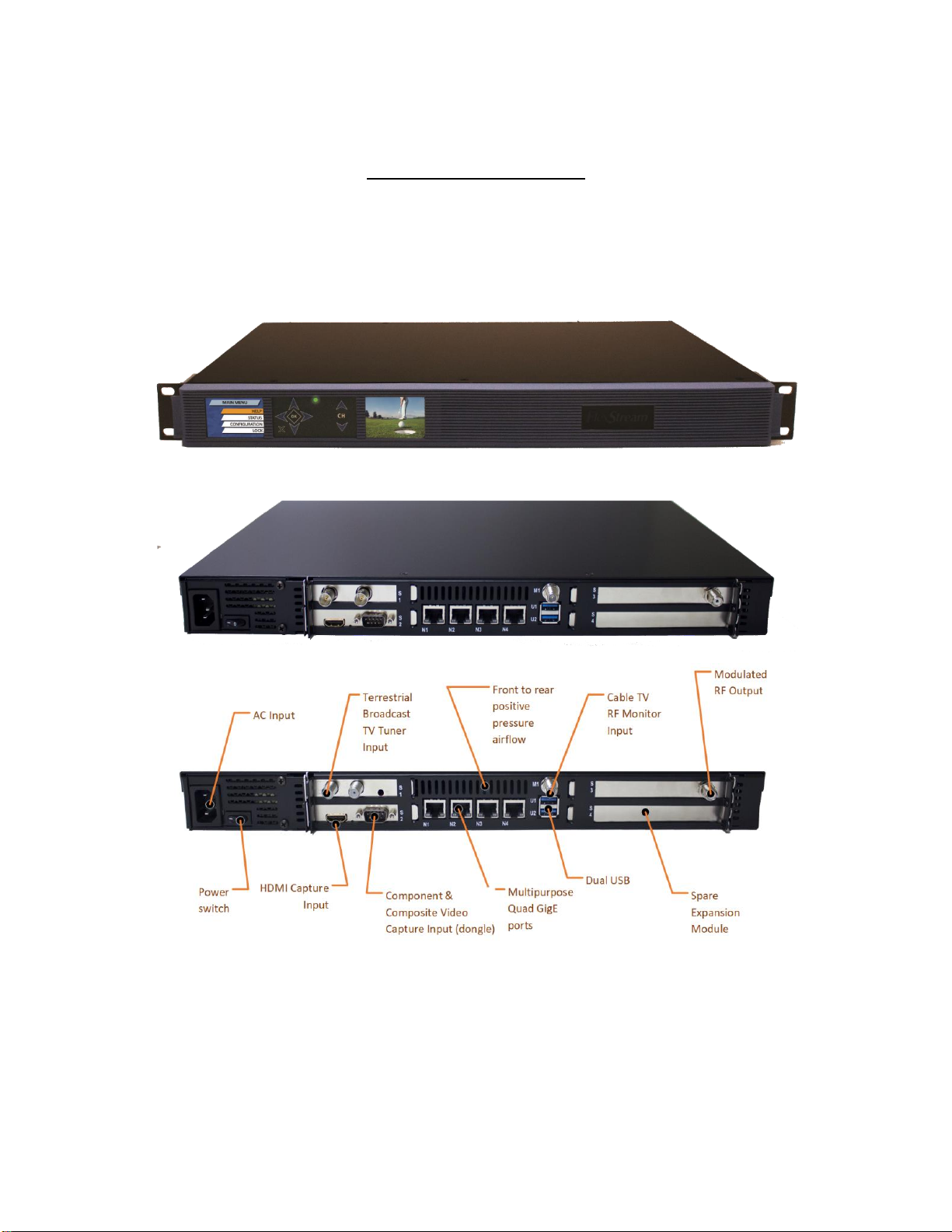
MX-400 Smart Headend
Thank you for purchasing the MX-400 Smart Headend Digital Video Media System. Thank you for
purchasing the MX-400HY digital video media system. This product family was designed to enhance the
value of TV networks in hotels, hospitals, schools and other institutions that utilize linear TV such as
COAX and IPTV. Using the existing coax infrastructure, or traditional IPTV, the MX-400 can create an
entire channel line-up or complement your existing one. By integrating the components of a traditional
headend into a single unit, and connecting these components with state of the art software, the MX-400
Smart Headend has taken headend technology to the next level. This feature rich, easily managed,
compact solution, is also very flexible. Configure each of the five module bays with the components
you need, or select a preconfigured model that meets your needs.
The MX-400 system can create TV channels from satellite or terrestrial broadcast TV, HDMI/HD-SDI
digital video sources, Component or Composite analog video sources, stored media recordings, RTSP
security cameras, IPTV, and HTML5 multi-media. This document will help you to get your MX-400 up
and running quickly. For your convenience a quick start section is provide at the end of this document.
See Appendix A –Quick Start Help. For more information please contact West Pond Enterprises sales or
support.
The single MX-400 system provides features that normally require a collection of rack mounted
equipment, set top boxes, and media servers. Integrating these components together not only reduces
the cost and space required to host the system, it creates a more reliable solution, creates a platform on
which advanced features can be developed, and simplifies overall operation. Our solution does not
require a dozen operating manuals, a single UI allows you to manage the entire system. Here’s a list of
standard equipment the MX-400 replaces.
Video Server / Streamer
o30 hours or more of video files onto the MX-400 and create custom TV channels via our
built in video server. Create a looping playlist or schedule playback at specific times.
Video Capture - HDMI / Component / Composite / HD-SDI / SDI
oCapture video and audio from the HD video port and encoded it to broadcast quality
standards.
Video Encoder
oThis box supports h.264 and MPEG2 video and a variety of audio formats. The number
and resolution of each encode is SW license dependent.
Digital Signage Player
oThe HTML5 video wrapper combines video streams with HTML5 media to create a
dynamic multi-media experience on one or more TVs without a digital signage player.
This powerful tool is made simple through presentation templates provided by West
Pond. See http://www.westpond.com/templates for a list of recent templates.
Demux –Remux Multichannel Multiplexer
oDemux MPTS feeds from satellite or terrestrial broadcast. Cherry pick the channels you
wish to include and ignore the rest.