Westbrook Trailers 48-072-KO12 User manual

Kit Trailer Assembly Instructions
Model: 48-048-KO8, 48-072-KO8/KO12
48-096-KO8 & 60-096-KO12
Carefully read and follow the assembly instructions in this manual.
Before using the trailer, carefully read the owner’s manual.
Video Assembly Instructions Available at
https://www.youtube.com/c/WestbrookTrailers
Save both manuals for future reference.
www.westbrooktrailers.com

2
Assembly instructions for kit trailers P.

3
Assembly instructions for kit trailers P.
Congratulations on the purchase of your kit trailer. Thank you for choosing Westbrook Trailers.
Safety Information
• It is important to read and understand all the instructions. Failure to follow all assem-
bly instructions may result in serious injury.
• The edges of the trailer frame can be sharp, it is IMPORTANT to ALWAYS wear the
provided safety gloves when handling the material during unboxing and the assembly
process.
• It is recommended that you use two people to assemble your trailer since you will
need to turn the trailer during the assembly.
• Modification of the trailer structure can make the trailer unsafe and void your
warranty. Any modifications made to the trailer must comply with DOT and NHTSA
regulations and must not compromise the gross vehicle weight rating (GVWR) of the
trailer.
Important Information
The paperwork needed to register your trailer is included in your kit. These are key documents
that must be submitted in order to register your trailer. They are enclosed in a brown envelope on
the outside of box #1.
The VIN label and UV overlay, the NVIS document for Canadian customers, and the Certificate of
Origin (Title) document for US customers will all be included.
If there are questions regarding the NVIS or Certificate of Origin, please contact us at 866-857-1445.
Write the VIN of the trailer and the purchase date in the space below.
Keep this manual and your receipt in a safe and dry place for future reference.
Serial Number : ______________________________ Purchase Date: _____________________
Unboxing your Trailer
Make sure you have received all three boxes of the kit trailer. If any parts are missing or broken,
please contact us at 866-857-1445 or email us at support@westbrooktrailers.com.When con-
tacting us about your trailer, please have the VIN of the trailer and the purchase order number
available.
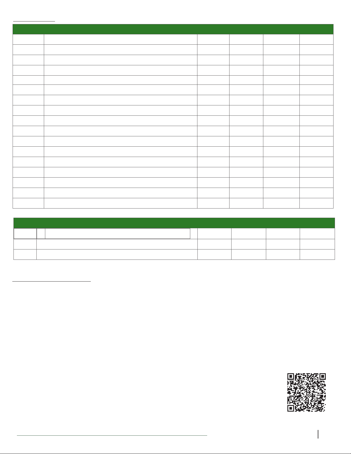
The kit trailer is shipped in 3 boxes containing the following parts:
4'x4' & 4'x6' & 4'x8'
• Box # 1 - Includes tires, fenders, lights, small parts, and hardware. Remove the registration
documentation affixed outside this box and keep it in a safe place until you are ready to
get a license plate.
• Box # 2 - Includes the axle and all the frame channels.
• Box # 3 - Includes both axle springs.
5'x8'
• Box # 1 - Includes tires, fenders, lights, small parts, and hardware. Remove the registration
documentation affixed outside this box and keep it in a safe place until you are ready to get a
license plate.
• Box # 2 - Includes all the frame channels.
• Box # 3 - Includes both axle and springs.

4
Assembly instructions for kit trailers P.

5
Assembly instructions for kit trailers P.
Part Listing
BOX # 1 - INTERIOR BOX - METAL
504447 FENDER PLATE - 8”/ 12" (504212) 2 222
504198 TONGUE SUPPORT FOOT 1 111
504471 STAKE POCKET 8 888
500259 LEAF SPRING MOUNTING BRACKET 4 444
500260 LEAF SPRING AXLE MOUNT PLATE 2 222
504162 5' TONGUE CONNECTION BRACKET 1 111
504163 LONG COUPLER CHANNEL 1 111
BOX # 1 TIRE & FENDER (INCLUDES ITEM LIST IN THE THREE BOXES INSIDE THE TIRE BOX)
ITEM# ITEM DESCRIPTION 4’ x 4’ 4’ x 6’ 4’ x 8’ 5’ x 8’
500258 8” FENDER 2 22
500841 4.80 X 8 LRC TIRE & WHEEL 2 22
504212 12" FENDER 2
500844 4.80 x 12 LRC TIRE ASSEMBLY 2
BOX # 1 - INTERIOR BOX - LIGHTS
500558 WIRE CONNECTOR 2 222
500513 TAILLIGHT LEFT/DRIVER SIDE 1 111
500514 TAILLIGHT RIGHT/PASSENGER SIDE 1 111
500515 AMBER MARKER LIGHT 2 222
500516 PLASTIC LICENSE BRACKET 1 111
500512 4 WAY FLAT 20’ WIRE HARNESS 1 111
BOX # 1 - INTERIOR BOX - HARDWARE (PICTURES ON THE RIGHT IN REAL SCALE FOR REFERENCE)
500814 3/8” U-BOLT 4 444
501049 3/8” X 3/4” HEX FLANGE BOLT 20 18 26 26
501033 3/8” X 1 1/2” HEX BOLT 10 13 20 20
501036 3/8” X 3/4” CARRIAGE BOLT 8 888
501031 3/8” HEX FLANGE LOCK NUT 46 46 61 61
501023 3/8” X 2-1/2” HEX BOLT 1 111
501024 3/8” X 3” HEX BOLT 2 222
501032 3/8” FLAT WASHER 8 444
501060 1/2” X 3 1/2” HEX BOLT 2 222
501056 1/2” LOCKING NUT 2 222
501065 9/16 UNF X 3” HEX BOLT 4 444
501066 9/16 UNF LOCKING NUT 4 444
501091 #10 X 1/2” PHILLIPS #2 SCREW 8 888
501092 #10 LOCKING NUT 8 888
501100 5/16 X 1/2” CUTTING SCREW 4 444
501001 1/2” WHEEL NUT 10 10 10 10
501073 1/4 X 3/4” HEX BOLT 32 32 32 32
501081 1/4 NYLON INSERT LOCKING NUT 32 32 32 32
500805 1 7/8” COUPLER CLASS I 1 111
500804 SAFETY CHAIN - 3/16 X 4’ (CLASS I) 1 111
503079 8” CABLE TIE 4 644

6
Assembly instructions for kit trailers P.
BOX # 2 - FRAME BOX
ITEM# ITEM DESCRIPTION 4’ x 4’ 4’ x 6’ 4’ x 8’ 5’ x 8’
500254 FRONT CHANNEL 1 111
500255 CROSS CHANNEL 1 245
500256 REAR CHANNEL 1 111
500251 4’ DRIVER SIDE CHANNEL (4X4) 1
500297 4’ PASSENGER SIDE CHANNEL (4X4) 1
500252 6’ DRIVER SIDE CHANEL (4X6) 1
500298 6’ PASSENGER SIDE CHANNEL (4X6 ) 1
500253 4’ FRONT DRIVER SIDE CHANNEL (4X8) 11
500299 4’ REAR DRIVER SIDE CHANNEL (4X8) 11
500300 4’ FRONT PASSENGER SIDE CHANNEL (4X8) 11
500301 4’ REAR PASSENGER SIDE CHANNEL (4X8) 11
500272 CONNECTION CHANNEL (4X8) 22
500257 TONGUE CHANNEL 2 222
504162 5’ - TONGUE CONNECTION BRACKET 1 111
500047 4’ STRAIGHT AXLE 1 11
504238 TONGUE CROSS CHANNEL 1
Part Listing
BOX # 3 SPRING
ITEM# ITEM DESCRIPTION 4’ x 4’ 4’ x 6’ 4’ x 8’ 5’ x 8’
500809 750 LB. SLIPPER SPRING 2 222
504617 5' STRAIGHT AXLE 1
Assembly Instruction:
You will need to prepare a large area to work. To make the assembly process easier, the instructions
have been divided into stages. Before beginning the assembly of each step, gather all of the parts
specified and carefully read all of the instructions. Halfway through the installation, you will need to
flip the trailer, which will require two people.
Required Tools:
• Ratchet with Socket : 10mm, ⁄”, ⁄” deep socket x 2, ½”, ⁄”, ⁄”, ⁄”,
• Wrench: ⁄”, ¾”, ⁄”
• Phillips Screwdriver
• Torque Wrench
• Knife
• Pliers
• Gloves (included)
• QR Code for assembly
***Video show assembly of 4' x 8' kit trailers, which includes most of the step
for all other sizes***

7
Assembly instructions for kit trailers P.
STEP 1– Stake Pocket Installation
ITEM # DESCRIPTION QTY
504471 STAKE POCKET 8
501073 1/4 X 3/4” HEX BOLT 32
501081 1/4 LOCKING NUT 32
1. Line the stake pocket to the pre-drilled holes of the frame and secure with ¼ x ⁄ hex
bolts and ¼ lock nut using ⁄ deep socket. Do this for all eight stake pockets.
BOX # 2 - FRAME BOX
ITEM# ITEM DESCRIPTION 4’ x 4’ 4’ x 6’ 4’ x 8’ 5’ x 8’
501171 ELECTRICAL GROMMET 4 612 14
500255 CROSS-CHANEL 1 24
504602 CROSS-CHANEL 5
500257 TONGUE CHANNEL 2 22
504601 TONGUE CHANNEL 2
504623 TONGUE CROSS-CHANNEL
STEP 2 - Electrical Grommet installation
1. Take one of the cross-channel and install the electrical grommet. Do this for all channels.
2. Then take one of the tongue channel and install the electrical grommet. Do this for both
tongue channels
*Kit trailers shipped prior to 2023 may not include the electrical grommet*

8
Assembly instructions for kit trailers P.
STEP 3a- Frame Assembly - 4’x 4’ Kit Trailer Frame
ITEM # PARTS DESCRIPTION QTY
501049 3/8 X 3/4” HEX FLANGE BOLT 6
501033 3/8 X 1-1/2” HEX BOLT (FULL THREAD) 6
501031 3/8 LOCK NUT 12
500254 FRONT CHANNEL 1
500255 CROSS CHANNEL 1
500256 REAR CHANNEL 1
500251 4’ DRIVER SIDE CHANNEL 1
500297 4’ PASSENGER SIDE CHANNEL 1
501171 ELECTRICAL WIRE GROMMET 2
IMPORTANT INFORMATION
• To avoid having to flip the trailer twice throughout the assembly, start with the frame UPSIDE
DOWN.
• We recommend that you complete one side before moving on to the other side.
• The longer hex bolts (3/8 X 1-1/2”) will be used to secure the plywood floor with frame.
• Assemble the frame but only tighten the hardware by hand, it will be tightened in a later
step, otherwise you will not be able to complete the tongue installation.
ASSEMBLY INSTRUCTION
1. Gather the frame pieces and the hardware placing them in their respective position as shown
in Figure 1.
2. When placing your frame piece, match the hole configuration shown in Figure 1. For
example, the passenger side channel the square holes should be facing up.
3. Both passenger and driver side channel overlaps with the front channel; do not insert one
inside the other. (see Figure #1 - Top right corner).
4. Loosely connect the first side channel using the 3/8 x 3/4" hex flange bolt and 3/8 lock nut on
the top, and the 3/8 X 1-1/2” hex bolt and 3/8 lock nut at the bottom. The 3/8 X 1-1/2” bolts will be
used to secure the plywood floor with frame.
5. Take a cross-channel and loosely connect it to the frame using the ⁄ x ⁄ flange bolt and ⁄
lock nut on top and the 3/8 X 1-1/2” hex bolt and 3/8lock nut at the bottom.
6. Repeat for other side.
7. Slide the rear channel over the passenger and driver’s side channel and loosely connect using
the 3/8 x 3/4" flange bolts and 3/8 lock nuts on top, and the 3/8 X 1-1/2”hex bolts and 3/8 lock
nuts at the bottom.

9
Assembly instructions for kit trailers P.
4’x 4’ Kit Trailer Frame
500251
500297
500254
500255
500256
Passenger Side
Driver Side
Back
Front
Only hand-tighten hardware at this step
Secure one side, before moving on to the next side
Figure 1.
FOR YOUR SAFETY
DO NOT STAND INSIDE
THE FRAME TO ASSEMBLE
The edges of the trailer can be very sharp.
To prevent injury, wear the provided safety gloves.
*FRAME IS UPSIDE DOWN - SQUARE HOLES FACING UP*
Once Upside down USE 501049 on top & 501033 on the bottom
Channel overlaps

10
Assembly instructions for kit trailers P.
Step 3b- Frame Assembly - 4’x 6’ Kit Trailer Frame
ITEM # PARTS DESCRIPTION QTY
501049 3/8 X 3/4” HEX FLANGE BOLT 4
501033 3/8 X 1-1/2” HEX BOLT (FULL THREAD) 8
501031 3/8 FLANGE LOCK NUT 12
500254 FRONT CHANNEL 1
500255 CROSS CHANNEL 1
500256 REAR CHANNEL 1
500252 6’ DRIVER SIDE CHANNEL 1
500298 6’ PASSENGER SIDE CHANNEL 1
IMPORTANT INFORMATION
• To avoid having to flip the trailer twice throughout the assembly, start with the frame UPSIDE
DOWN. We recommend that you complete one side before moving on to the other
• The longer hex bolts (3/8 X 1-1/2”) will be used to secure the plywood floor with frame.
• Assemble the frame but only hand-tighten the hardware, they will be tightened in a later
step.
ASSEMBLY INSTRUCTION
1. Gather the frame pieces and the hardware placing them in their respective position as shown
in Figure 1.
2. When placing your frame piece, match the hole configuration shown in Figure 1. For
example, the passenger side channel the square holes should be facing up.
3. Both passenger and driver side channel overlaps with the front channel; do not insert one
inside the other. (see Figure #1 - Top right corner).
4. Loosely connect the first side channel using the 3/8 X 3/4” hex flange bolt and 3/8 lock nut on
the top, and the 3/8 X 1-1/2” hex bolt and 3/8 lock nut at the bottom. The 3/8 X 1-1/2” hex flange
bolts will be used to secure the plywood floor with frame.
5. Take a cross-channel and loosely connect both to the frame using the 3/8 X 1-1/2” hex bolt and
3/8 lock nut at the bottom only. The top will be secured when you install the axle.
6. Repeat for other side.
7. Slide the rear channel over the passenger and driver’s side channel and loosely connect using
the 3/8 X 3/4” hex flange bolts and 3/8 lock nuts on top, and the 3/8 X 1-1/2” hex bolts and 3/8
lock nuts at the bottom.

11
Assembly instructions for kit trailers P.
500254
500255
500256
500255
500252
500298
Passenger side
Driver Side
Back
Front
4’x 6’ Kit Trailer Frame
Figure 1.
FOR YOUR SAFETY
DO NOT STAND INSIDE
THE FRAME TO ASSEMBLE
*FRAME IS UPSIDE DOWN - SQUARE HOLES FACING UP*
Once Upside down USE 501049 on top & 501033 on the bottom
Only hand-tighten hardware at this step
Secure one side, before moving on to the next side
The edges of the trailer can be very sharp.
To prevent injury, wear the provided safety gloves. Channel overlaps

12
Assembly instructions for kit trailers P.
Step 3c- Frame Assembly - 4’x 8’ Kit Trailer Frame
ITEM # PARTS DESCRIPTION QTY
501049 3/8 X 3/4” HEX FLANGE BOLT 12
501033 3/8 X 1-1/2” HEX BOLT (FULL THREAD) 8
501031 3/8 NYLON INSERT HEX FLANGE LOCK NUT 20
500254 FRONT CHANNEL 1
500255 CROSS CHANNEL 4
500256 REAR CHANNEL 1
500253 4’ FRONT DRIVER SIDE CHANNEL 1
500299 4’ REAR DRIVER SIDE CHANNEL 1
500300 4’ FRONT PASSENGER SIDE CHANNEL 1
500301 4’ REAR PASSENGER SIDE CHANNEL 1
500272 CONNECTION CHANNEL 2
IMPORTANT INFORMATION
• To avoid having to flip the trailer twice throughout the assembly, start with the frame UPSIDE
DOWN. We recommend that you complete one side before moving on to the other.
• The longer hex bolts (3/8 X 1-1/2”) will be used to secure the plywood floor with frame.
• Assemble the frame but only hand-tighten the hardware, they will be tightened in a later
step.
ASSEMBLY INSTRUCTION
1. Gather the frame pieces and the hardware placing them in their respective position as shown
in Figure 1.
2. When placing your frame piece, match the hole configuration shown in Figure 1. For
example, the passenger side channel the square holes should be facing up.
3. Both passenger and driver side channel overlaps with the front channel; do not insert one
inside the other. (see Figure #1 - Top right corner).
4. Loosely connect the first side channel using the 3/8 X 3/4” hex flange bolt and ⁄ lock nut on
the top, and the 3/8 X 1-1/2” hex bolt and ⁄ lock nut at the bottom. The 3/8 X 1-1/2” bolts will be
used to secure the plywood floor with frame.
5. Take the first cross-channel and loosely connect it to the frame using the 3/8 X 3/4” flange
bolt and ⁄ lock nut on top and the 3/8 X 1-1/2” hex bolt and ⁄ lock nut at the bottom.
4. Slide the connection channel over top of the front and back side channels. Then add the
second cross-channel to the first hole of the connection channel and fasten all three channels
at the bottom only using the 3/8 X 1-1/2” hex bolt 3/8 lock nut. The top will be secured when
you install the axle.
6. Loosely connect the center of the connection channel using the 3/8 X 3/4” flange bolts and 3/8
lock nut on top, and the 3/8 X 1-1/2” hex bolt and 3/8 lock nut at the bottom.
7. Connect the third cross-channel to the last hole of the connection channel and fasten all three
channel at the bottom using the 3/8 X 1-1/2” hex bolt 3/8 lock nut. The top will be secured
when you install the axle.
8. Repeat step 2 for the fourth cross-channel
9. Repeat steps 1 – 6 for the other side. Repeat for other side.
10. Slide the rear channel over the passenger and driver’s side channel and loosely connect using
the 3/8 X 3/4” hex flange bolts and 3/8 lock nuts on top, and the 3/8 X 1-1/2” hex bolts and 3/8
lock nuts at the bottom.
Figure 1.

13
Assembly instructions for kit trailers P.
4’x 8’ Kit Trailer Frame
500254
500255
500256
500255
500255
500255
500301
500299
500272
500272
500300
500253
Passenger Side
Driver Side
Back
Front
Figure 1.
The edges of the trailer can be sharp.
To prevent injury, wear the provided safety gloves.
FOR YOUR SAFETY
DO NOT STAND INSIDE
THE FRAME TO ASSEMBLE
*FRAME IS UPSIDE DOWN - SQUARE HOLES FACING UP*
Once Upside down USE 501049 on top (Short)
& 501033 on the boom (Long)
Only hand-ghten hardware at this step
Secure one side, before moving on to the next side
Channel manufactured
before November 2022
will not have this extra
hole. This hole is only
used for 5'x8' trailers.
Channel overlaps

14
Assembly instructions for kit trailers P.
ITEM # PARTS DESCRIPTION QTY
501049 3/8 X 3/4” HEX FLANGE BOLT 14
501033 3/8 X 1-1/2” HEX BOLT (FULL THREAD) 14
501031 3/8 NYLON INSERT HEX FLANGE LOCK NUT 28
504599 FRONT CHANNEL 1
504602 CROSS CHANNEL 5
504600 REAR CHANNEL 1
500253 4’ FRONT DRIVER SIDE CHANNEL 1
500299 4’ REAR DRIVER SIDE CHANNEL 1
500300 4’ FRONT PASSENGER SIDE CHANNEL 1
500301 4’ REAR PASSENGER SIDE CHANNEL 1
500272 CONNECTION CHANNEL 2
501171 ELECTRICAL WIRE GROMMET 10
IMPORTANT INFORMATION
• To avoid having to flip the trailer twice throughout the assembly, start with the frame UPSIDE
DOWN. We recommend that you complete one side before moving on to the other.
• The longer hex bolts (3/8 X 1-1/2”) will be used to secure the plywood floor with frame.
• Assemble the frame but only hand-tighten the hardware, they will be tightened in a later step.
ASSEMBLY INSTRUCTION
1. Gather the frame pieces and the hardware placing them in their respective position as shown in
Figure 1.
2. When placing your frame piece, match the hole configuration shown in Figure 1. For example, the
passenger side channel the square holes should be facing up.
3. Both passenger and driver side channel overlaps with the front channel; do not insert one inside
the other. (see Figure #1 - Top right corner).
4. Loosely connect the first side channel using the 3/8 X 3/4” hex flange bolt and 3/8 lock nut on the
top, and the 3/8 X 1-1/2” hex bolt and ⁄ lock nut at the bottom. The 3/8 X 1-1/2” hex bolts will be used
to secure the plywood floor with frame.
5. Slide the connection channel over top of the front and back side channels.
6. Take the first cross-channel and install a grommet on each hole, then d align with the first hole of
the connection channel. Loosely secure all three channels at the bottom only with the 3/8 X 1-1/2”
hex bolt 3/8 lock nut. When you put the axle in place, the top will be held in place.
7. Position the second cross-channel opening toward the front channel and the third one facing the
opposite way (figure 1). Loosely connect both cross-channels to all three channels and loosely fasten
at the bottom using the 3/8 X 1-1/2”hex bolt 3/8 lock nut and at the top with 3/8 X 3/4” hex flange bolt
and 3/8 lock nut.
8. Connect the fourth cross-channel to the last hole of the connection channel and fasten all three
channel at the bottom using the 3/8 X 1-1/2” hex bolt 3/8 lock nut. The top will be secured when you
install the axle.
9. The 3/8 X 3/4” flange bolts and 3/8 lock nut on top and the 3/8 X 1-1/2” hex bolt and 3/8 lock nut (on
the bottom are used to attach the fifth connection channel.
10. Repeat steps 1 – 5 for the other side.
11. The 3/8 X 3/4” flange bolts and 3/8 lock nuts on top and the 3/8 X 1-1/2” hex bolts and 3/8 lock nuts on
the bottom are used to connect the rear channel to the passenger and driver's side channels.
Step 3d- Frame Assembly - 5’x 8’ Kit Trailer Frame

15
Assembly instructions for kit trailers P.
5’x 8’ Kit Trailer Frame -
The edges of the trailer can be sharp.
To prevent injury, wear the provided safety gloves.
504599
504602
504600
504602
504602
504602
500301
500299
500272
500272
500300
500253
Passenger Side
Driver Side
Back
Front
Figure 1.
FOR YOUR SAFETY
DO NOT STAND INSIDE
THE FRAME TO ASSEMBLE
504602
*FRAME IS UPSIDE DOWN - SQUARE HOLES FACING UP*
Once Upside down USE 501049 on top & 501033 on the boom
Only hand-ghten hardware at this step
Secure one side, before moving on to the next side
Channel overlaps

16
Assembly instructions for kit trailers P.
ITEM # DESCRIPTION QTY
500047 or 504617 4’ STRAIGHT AXLE or 5' STRAIGHT AXLE 1
500809 750 LB. SPRINGS 2
500814 3/8-16 U-BOLT 4
500259 LEAF SPRING MOUNTING BRACKET 4
500260 LEAF SPRING AXLE MOUNT PLATE 2
501031 3/8 NYLON INSERT HEX FLANGE LOCK NUT 16
501036 3/8 X 3/4” CARRIAGE BOLT 8
501032 3/8” FLAT WASHER 8
501065 9/16-18 UNF X 3” HEX BOLT 4
501066 9/16-18 UNF NYLON INSERT LOCKING NUT 4
STEP 4 – Axle Assembly

17
Assembly instructions for kit trailers P.
STEP 4 – Axle Assembly
1. Secure the leaf spring mounting brackets in the square holes on each side of the trailer with the
carriage bolt 3/8 X 3/4” and 3/8 lock nut using 9/16 socket; the round holes of the brackets should
be oriented closest to the center.
2. Where there is no cross-channel at the fastening location of the mounting bracket use a 9/16"
washer as a spacer.
3. Lay the axle between the mounting brackets.
4. Place the springs inside the mounting bracket with eye of the spring towards the front and the
flat side towards the back of the trailer. Secure the spring to mounting bracket with the 9/16-18
UNF X 3” hex bolts and 9/16 lock nuts using 7/8" socket and wrench.
5. Do not over-tighten as there needs to be movement in the spring. Do this for both sides.
6. Place the first U-bolt around the axle. Line up the leaf spring mount plate with the oval holes run-
ning in the same direction as your leaf spring. Hand-tighten with the 3/8 locking nut. Repeat for
all other U-bolts.
7. Secure all the U-bolts with a 9/16" socket.
8. Using two people, flip the frame.
CAUTION! FLIPPING THE TRAILER OVER REQUIRES TWO PEOPLE!
The hole in the mounting should be facing each other.
Where there is no
cross-channel at the fasten-
ing location of the mount-
ing bracket use a 3/8 wash-
er as a spacer.

18
Assembly instructions for kit trailers P.
Step 5– Fender & Wheels
ITEM # DESCRIPTION QTY
501091 #10 X 1/2” PHILLIPS #2 MACHINE SCREW 8
501092 #10 LOCKING NUT 8
501049 3/8 X 3/4” HEX FLANGE BOLT 6
501031 3/8 NYLON INSERT LOCKING NUT 6
501001 1/2” WHEEL NUTS 10
48-048-KO8, 48-072-KO8, 48-096-KO8 (8” Wheel)
500258 8” FENDER 2
500841 4.80 X 8 LRC TIRE & WHEEL 2
504447 FENDER PLATE - 8” 2
48-072-KO12, 48-096-KO12,60-096-KO12 (12” Wheel)
504212 12” FENDER 2
500844 4.80 X 12 LRC TIRE & WHEEL 2
504476 FENDER PLATE - 12” 2
1. Align the fender support plate with the frame and secure with the #10 machine screws and
#10 lock nuts using a 3/8" socket and Phillips screwdriver. If the holes are not perfectly aligned
use a punch to align them.
2. Place the fender over top of the fender plate, hand-tighten the top hole using the 3/8 X 3/4”
hex flange bolt and 3/8 lock nut, making sure the nut is inside of the fender.
3. Place the tire on the hub and secure it to the rim with 1/2" wheel nuts using 13/16" socket and
torque to 95ft-lbs.
4. Hand tighten the other two holes to the frame using the 3/8 X 3/4” hex flange bolts and 3/8
lock nuts.
5. Tighten all the fender bolts using a 9/16" socket and wrench.
6. Repeat for other side.
7. Make sure wheel nuts are installed in same position as shown in picture.

19
Assembly instructions for kit trailers P.
Step 6 - Tongue Assembly
ITEM # DESCRIPTION 4 FT 5 FT
500257 TONGUE CHANNEL 2 2
504623 TONGUE CROSS CHANNEL 1
504162 5’ - TONGUE CONNECTION BRACKET 1 1
501049 3/8 X 3/4” HEX FLANGE BOLT 8 10
501033 3/8 X 1-1/2” HEX BOLT (FULL THREAD) 4 6
501031 3/8 NYLON INSERT HEX FLANGE LOCK NUT 4 6
501100 5/16 UNC X 1/2” CUTTING SCREW 4 4
500512 4 WAY FLAT 20’ WIRE HARNESS 1 1
501171 ELECTRICAL WIRE GROMMET 4 4
1. Take the two tongue channels and slide them through the vertical slots of the front channel
and hand tighten to the frame in two places using the 3/8 X 1-1/2” hex bolts and 3/8 lock nuts on
top and the flange bolts 3/8 X 3/4” and 3/8 lock nuts at the bottom.
2. If the tongue is not aligning with the frame's holes, make sure all bolts are loose.
2a. FOR 5X8 TONGUE ASSEMBLY ONLY*
Put tongue cross channel in between tongue channel and fasten it with the 3/8 X 1-1/2” hex bolts
and ⁄ lock nuts on top and the flange bolts 3/8 X 3/4” and 3/8 lock nuts at the bottom.

20
Assembly instructions for kit trailers P.
Step 7 - Tongue Connection Support Installation
1. Put the tongue connection bracket with the threaded holes facing up place without sliding it
fully into position.
2. Feed each wire of the wire harness between the tongue channel and separate your wire as
follows.
• Yellow wire and brown wire on the driver’s side
• Green wire and brown wire on the passenger’s side
• Do not pull the white wire through, you will secure it to the coupler channel once it’s as-
sembled.
3. Slide the tongue connection bracket in place and hand tighten using the 3/8 X 3/4” flange
bolts on top.
4. On the bottom, in the four pre-drilled holes, secure with the cutting screws using a 1/2" socket.
5. Secure the top bolts using 9/16" socket.
6. Tighten all the bolts of the trailer frame using a 9/16" socket and wrench. If you are going
to add a plywood sheet before using the trailer, you don’t need to tighten the top bolts
until the plywood has been added.
This manual suits for next models
4
Table of contents
Other Westbrook Trailers Utility Vehicle manuals