Westell VirtualEdge VELGX-90 User manual

Section VEL‐GX9‐20A
R
Equipment Issue A
030‐300323 Rev. A, June 2014
1406IARAD4c
ECopyright 2014 Westell, Inc. All rights reserved. LGXris a registered trademark of Furukawa Electric North America, Inc.
Westellrand VirtualEdgerare registered trademarks of Westell, Inc. Page 1 of 7
VirtualEdgerVELGX‐90 Media Panel, with
Nine LGX‐Type Positions, Front Tray, and Top Cover
PART # PAGE #
1. GENERAL 1....................................
2. INSTALLATION 2...............................
3. CUSTOMER & TECHNICAL SERVICES 6.........
4. WARRANTY & REPAIRS 4.......................
5. SPECIFICATIONS 5.............................
1. GENERAL
1.1 Document Purpose
This practice describes Westell's VirtualEdgerVELGX‐90, a
universal media panel with nine, 118mm, LGXr‐type panel po
sitions, as shown in Figure 1 (field‐populated version shown in
Figure 2). Westell offers a variety of panels, couplers, cables,
and other orderable options for terminating services for use
with the VELGX‐90 or other models in the VirtualEdge fami
ly. Contact Westell for details.
‐ NOTE ‐
Hereafter, the Westell VirtualEdge VELGX‐90 Universal Panel
may be referred to as “the panel” or the “VELGX‐90.”
1.2 Document Status
Whenever this installation guide is updated, the reason will be
stated in this paragraph.
1.3 Product Purpose and Description
The VirtualEdge (VE) VELGX‐90 is a universal, LGX‐com
patible interface panel used at the CPE point of demarcation.
It has nine, empty, rectangular cut‐outs designed to accept
118mm LGX‐type panels and/or LGX‐sized fiber cassettes. A
circuit identification (ID) card is provided inside a clear plastic
packet, which allows installers to label each coupler position.
LGX adapter panels are NOT provided.
Only 4 panels shown populated in this figure.
Figure 1. Isometric View of Empty VELGX‐90 Panel
Figure 2. VELGX‐90 with 4 Populated Panels, Clips/Clamps
Circuit ID card
in clear packet
The VELGX‐90 comes equipped with a front‐mounted cable
management fiber tray, 8 cable management D‐rings, 2 mount
ing ears, a detachable top cover, and includes the components
shown in Table 1. Optional features include LGX adapter pan
els, couplers, fiber cassettes/trays and D‐rings.
Quantity Component Description
1 Panel 3.5” high (2 RUs) panel frame, with 9 empty positions for LGX adapter panels (or for LGX‐sized fiber cassettes), 2 hole sets for rack ears at
sides, wall‐mount holes in bottom & rear sides, small square perimeter holes for mounting cable management D‐rings
1Top cover Easy‐on/easy‐off detachable, low‐profile, top cover
1 Tray Front‐mounted cable management tray with holes for D‐rings for convenient cable support & management at the front of the panel
2 Mounting
ears
Adjustable/reversible for 19 or 23” racks or wall‐mounting, with 8 screws to attach ears to panel and panel to rack (in parts bag)
8 D‐rings 8 cable management D‐rings or clips, overlapping ends for easy cable/fiber entry, square posts mount in square holes
2Push‐pins 2 spare Nylatch push‐pin fasteners to mount and secure LGX panels on product
Orderable Options & Accessories
LGX Panels Empty, solid, or populated 118mm LGX‐type, detachable, adapter panels. Includes 2 push‐pins.
Splice Tray LGX‐sized splice tray
Fiber Cassette Westell, Corning or TE 118mm fiber cassette or the JDSU BrightJack
Table 1. VELGX‐90 Components & Options

Section VEL‐GX9‐20A 030‐300323 Rev. A R
21406IARAD4c
Figure 3. Dimensions for Rack Mounting
19.2”
18.3”
16.8"
3.47"
(2 RUs)
16.8"
23.4”
22.3”
19” Rack Mounting 23” Rack Mounting
LGX panels are not provided with the VELGX‐90
1.4 Product Mounting
The panel can be flush wall‐mounted using the keyhole‐shaped
mounting holes on either the bottom or the rear surfaces, or it can
be rack mounted using the included reversible mounting ears (in
cluded in the bag of parts) which can be attached to the side walls.
Tw o s e t s of r a c k ‐ m o u n t i n g e a r h o l e s on the side walls allow flush
or projected positions in both 19” and 23” standard EIA relay
racks. Optionally, flip and reposition the ears in the rear mounting
hole set for an alternate type of wall‐mounting. See Part 2 and
Figure 4 for more detailed mounting information.
1.5 Applications
To enable a greater variety of service and interface offerings,
service providers are putting more fiber into customer prem
ises, either with Fiber‐to‐the‐Premise or placing more fiber
multiplexers and IP aggregation devices closer to subscribers.
In business markets, the strong demand for Transparent LAN
and Virtual Private Network services creates numerous ap
plications for Westell's VirtualEdge panels. These panels are
intended to be simple, sturdy, and versatile mechanical plat
forms, used to terminate high‐speed Ethernet, fiber, or copper
services in any combination(s). Additional interfaces can also
be installed on a per‐circuit basis.
See Figure 4 for a view of a VELGX‐90 populated with 8 LGX
panels. See Figure 5 for a view of the VELGX‐90 equipped
with cable management clips and cable clamps (top cover off).
1.6 Product Features
The VELGX‐90 panel offers the following features.
D2 Rack Units (2 RUs) high
D9 horizontal, empty, LGX‐type cut‐out positions (118mm)
to accept any field‐provided LGX‐type panel, cassette, or
insert, such as:
d118mm‐LGX‐type panels (which may contain any
combination of SC or LC type fiber couplers, RJ45
[Cat5e for Ethernet] couplers, BNC [DS3] couplers,
or any other Keystone type coupler)
d118mm‐LGX‐sized fiber cassettes
d118mm‐LGX‐sized splice trays
dJDSU BrightJack
DMounts on wall or in 19” or 23” relay racks or cabinets
DAdjustable, reversible, mounting ears
DVELGX‐90 chassis/framework provides cable support and
cable tie‐downs for cables coming from the Network/Cus
tomer Premises
DFront tray and D‐rings for convenient front panel cable
management
DSteel construction
DCircuit identification card
DRack mounting hardware included
DTwo dual ground posts and one dual ground lug
DOptional couplers, additional cable management clips/
rings, cable clamps, pigtail fan‐outs, and fiber kits available
(contact Westell for details)
‐ PRECAUTIONARY STATEMENT ‐
Never install telephone wiring during a lightning storm.
Never install telephone jacks in wet locations unless the jack
is specifically designed for wet locations.
Never touch uninsulated telephone wires or terminals unless
the telephone line has been disconnected at the network
interface.
Use caution when installing or modifying telephone lines.
‐ INSPECTION NOTE ‐
Visually inspect the unit for damages prior to installation. If the
equipment has been damaged in transit, immediately report the
extent of the damage to the transportation company and to West
ell (see Part 3 for telephone number).
2. INSTALLATION
The VELGX‐90 panel can be mounted on a wall or in 19” or 23”
relay racks with standard EIA 1.75” hole spacing. The follow
ing paragraphs and Figure 4 provide further details. Screws to
attach the mounting ears to the panel are provided, as well as
screws to mount the panel to a rack.
2.1 Mounting in a 19” Rack (Figure 4)
The panel is shipped from the factory pre‐assembled. Each
panel includes two, L‐shaped, reversible mounting ears (lo
cated in the bag of parts). When rack mounting, the panel can
be installed so the front of it (without the front tray) is flush
with the front of the rack, or mounted in a projected position
in the rack. For 19” rack mounting, the mounting ear's short
flange attaches to the rack channel.

Section VEL‐GX9‐20A
030‐300323 Rev. A
R
3
1406IARAD4c
‐ PROJECTION NOTE ‐
The front tray, when attached, projects forward from the rack.
Minimize the projection by attaching ears in the rear‐most set of holes
in the ear's long flange (19” racks only, see bottom of Figure 4).
1. Determine vertical position in rack. Select the vertical
mounting location in the rack. This panel requires two ver
tical Rack Units (2 RUs) in a standard Telco relay rack.
2. Remove ears from bag. Locate the bag of parts shipped
with the panel and remove the two L‐shaped mounting
ears and the rack mounting hardware. Each ear flange has
several sets of mounting holes in it.
3. Attach long flange of ear to panel. Attach both ears to the
forward position on the side walls of the panel, using the
hardware provided. Place the ear's long flange against the
panel, line up the holes in the ear with the holes in the side
of the VELGX‐90, then insert and thread the provided
mounting screws through the holes. Repeat for the other
ear. Tighten all screws.
4. Attach panel to rack. Lift the panel and attach it to the rack
channels in the correct vertical rack position. Align the
holes in the ear's short flange with the proper holes in the
rack channels, at either the front or back side of the chan
nel, per company practice. Insert the provided screws into
the aligned set of holes, then tighten the screws. Repeat
for the other ear.
2.2 Mounting in a 23” Rack
The panel is shipped from the factory pre‐assembled. Each
panel includes two, L‐shaped, reversible mounting ears (lo
cated in the bag of parts). For 23” rack mounting, the mounting
ear's long flange attaches to the rack channel.
1. Determine vertical position in rack. Determine and select
the vertical mounting location in the rack. This panel re
quires two vertical Rack Units (RUs) in a standard Telco
relay rack.
2. Remove ears from bag. Locate the bag of parts shipped
with the panel and remove the two L‐shaped mounting
ears and the rack mounting hardware. Each ear flange has
several sets of mounting holes in it.
3. Attach short flange of ear to panel. Attach both ears to the
to the forward position on the side walls of the panel, using
the hardware provided. Place the ear's short flange against
the panel, line up the holes in the ear with the holes in the
side walls of the VELGX‐90, then insert and thread the
provided mounting screws through the holes. Repeat for
the other ear. Tighten all screws.
4. Attach panel to rack. Lift the panel and attach it to the rack
channels in the correct vertical rack position. Align the
holes in the ear's long flange with the proper holes in the rack
channels. Insert the provided screws into the aligned set of
holes, then tighten the screws. Repeat for the other ear.
2.3 Mounting on a Wall
The VELGX‐90 can be flush‐mounted horizontally or vertically
on a wall or backboard using the keyhole‐shaped mounting holes
on either the bottom surface or on the rear wall of the unit (see
Figure 7); or alternately, the mounting ears can be attached near
19” Rack Mounting
23” Flush Rack Mounting
Attach long flange of ear to VELGX‐90 panel
Attach panel to rack**
D
D
Attach short flange of ear to VELGX‐90 panel
D
Attach panel to rack**
D
short flange of
ear* attaches to
rack channel
Cable management
Attach ears* to
either the front or
the rear hole set
Mount optional
cable clamps
at rear
For 23" racks, long flange of ear
attaches to either the front or back
side of the rack channel
rings can mount here
For 19" racks,
* Mount panel to either the front
or rear side of rack channel.
* Mount panel to either the front
or rear side of rack channel.
Figure 4. Flush 19” Rack Mounting
Figure 5. Flush 23” Rack Mounting (Top Cover Plate Removed)
Top cover on
Figure 6. Optionally Attaching Ears for Wall Mounting
Attach ears here for
walll mounting
Field‐populated panel shown
Empty panels shown
Clips/rings can be
mounted here
Field‐populated panel show
n
Option 1
Attach ears here for
alternate wall mounting
Option 2
Top cover plate removed to
show optional locations and
positions of fiber cable rings
Ears are NOT required for wall mounting
Use rear‐most hole set in
ears to set panel further
back in rack (less projection
due to front‐attached tray)
Ear attached in furthest
forward position

Section VEL‐GX9‐20A 030‐300323 Rev. A R
41406IARAD4c
Keyhole‐shaped
Figure 7. Top/Rear View Showing Keyhole Mounting Holes
Top cover plate lifted for visual clarity
Rear‐wall
wall‐mount hole
Keyhole‐shaped
Bottom‐wall
wall‐mount hole
the back of the unit for wall mounting. Follow local codes and
company practices for the proper wall type.
‐ WALL MOUNTING WITH EARS NOTE ‐
As an option, the rack mount ears can be used for wall‐mounting the unit,
using the last, rear‐most, hole‐set on the sides of the VELGX‐90. As
shown in Figure 9, this mounting configuration provides an additional 2”
of free space at the rear of the unit for cables, etc., if desired. Note that ca
ble clamps will not work well with this mounting option.
1. Determine position on wall. Select the mounting location
on the approved wall. The VELGX‐90 may be mounted
horizontally or vertically with the large bottom surface
abutting the wall (Figure 8), or with the smaller rear sur
face abutting the wall (Figure 7).
2. Mark and drill holes. Place the VELGX‐90 against the
wall in the desired mounting location, then mark the
mounting hole locations to be drilled. Set the unit aside
then drill the mounting holes, per company practice. Do
not drill holes too big.
3. Partially install screws. Install a screw (with a head diame
ter smaller than the diameter of the largest part of the
keyholes on the unit) into each drilled hole in the wall and
thread it into the wall until only ¼ remains and protrudes
from the wall. Repeat for each screw.
4. Hang unit from protruding screws. Lift then hang the unit
(at the keyhole‐shaped mounting holes) from the protrud
ing screws in the wall. Slide the unit left or right, or up or
down, til the narrow part of the keyholes are behind the
screw heads.
5. Tighten the screws. Finish driving all mounting screws un
til hand‐tight. Attempt to wiggle the unit to test the
installation stability. Correct any instability.
2.4 Making Ground Connections
The Westell VE panels are shipped from the factory with
ground lug posts (see Figure 11) capable of accepting #6
ground wire for rack and wall‐mount applications. The install
er should make a ground connection to the ground posts using
Figure 8. Typical Wall Mounting Views, Mounting Ears Not Used
Flush Wall Mounting*
Place VELGX‐90 against wall in desired orientation
D
D
Attach panel to wall
D
* Can be mounted using the rack‐mount ears attached in the side wall's hole set closest to the rear of the unit.
** Wall‐mount holes are also located on the rear wall of the VELGX‐90
Alternately,
90 degrees and
attach to wall via
these holes in the
unit's rear wall**
Mark then drill mounting holes in wall at keyhole‐shaped mounting
hole locations on bottom surface of VELGX‐90
Keyhole‐shaped
mounting hole
(1 of 4)
rotate unit
Keyhole‐shaped
mounting hole
(1 of 4)
Top cover removed in these views
Horizonal
Mounting
Vertical
Mounting

Section VEL‐GX9‐20A
030‐300323 Rev. A
R
5
1406IARAD4c
Figure 9. Wall Mount Ear Position for Extra Rear Space
Fiber cable
Top/Side View
Mount ears as shown
2”
cable space
at rear of unit
rings can be
rotated 90
degrees, as
in last hole set
for 2" of extra
needed
Circuit ID card
an approved ground strap or #6 ground wire, then ground the
panel to an earth ground or according to local installation pro
cedures for grounding and bonding equipment.
‐ GROUNDING NOTE ‐
Always follow local safety precautions and standard operating proce
dures for grounding the equipment when installing, upgrading, repairing
or maintaining equipment. Any instructions or information contained
herein is subordinate to local codes, operating procedures or practices.
2.5 Making Installer Connections
After the panel is mounted, up to nine separately‐ordered
LGX panels fiber cassettes (fiber trays) may be installed at the
front of the VELGX‐90. A variety of LGX type panels or cas
settes can be installed, as well as various types of keystone
couplers may be installed in any LGX panel, per company prac
tice. After LGX panels and keystone couplers are installed,
fiber cable connections are made at the front of the
VELGX‐90. Use the provided circuit ID card (see Figure 9 and
Figure 10), folded up and located in a clear packet on the top
cover, as connections are made, to identify each line.
‐ CAUTION ‐
Use care when installing and removing couplers and adapter
panels ‐ do not force into place. If a coupler resists insertion,
remove it and check for debris in or near the coupler or hole.
Then gently re‐insert the coupler.
2.5.1 Installing Provided Fiber Cable Management Rings
Cable management D‐rings or clips are provided to assist in
neat management of the fiber cables and to provide safe guid
ance and support of the cables that run to and from the LGX
panels and couplers. Westell provides 8 fiber rings, shipped
loose in a bag of parts. They may be installed near the front,
back, and side edges of the VELGX90, in the small square
mounting holes provided. Any ring may be rotated 90 degrees,
to accommodate cables entering the VELGX‐90 from any di
rection. The design of the provided rings allows existing or
newly‐installed cables/jumpers to be safely contained yet easily
inserted into the ring, without disconnecting, re‐feeding, or re‐
routing. Route the fiber through the contact‐free gap between
the ends of the ring, flexing the ends if or as needed, then direct
the fiber toward the center of the fiber ring.
Figure 10. Circuit ID Card (Located in Clear Packet on Top Cover)

Section VEL‐GX9‐20A 030‐300323 Rev. A R
61406IARAD4c
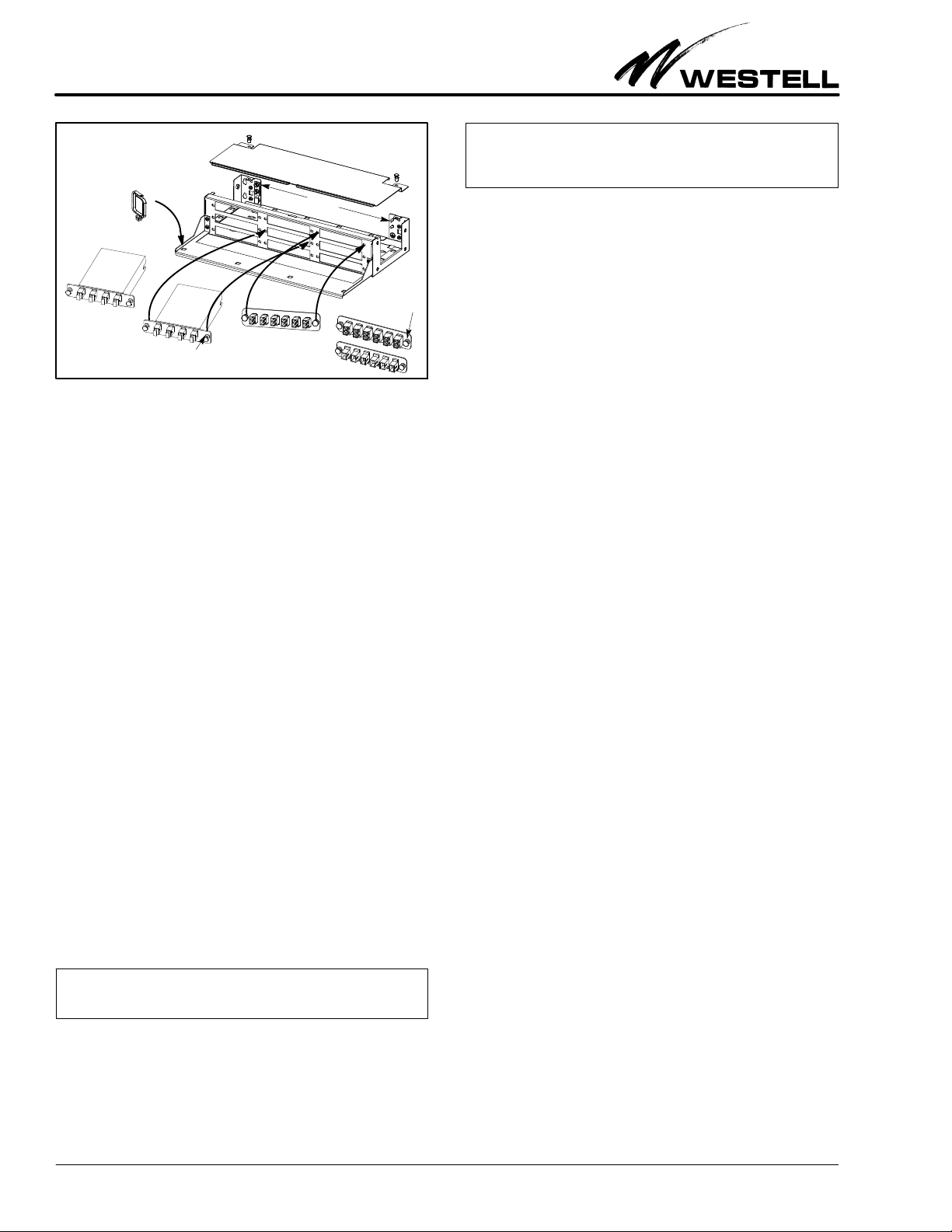
Figure 11. Inserting LGX Panels and Fiber Cassettes
Insert adapter panels and cassettes from the
front of the VELGX‐90. Align Ny‐latch push‐
pins with the mounting holes on both
sides of the LGX slot, then insert/press
push‐pins til they snap in place.
Ny‐latch
fastener (push‐pin)
LGX‐type
fiber cassettes
LGX adapter panels
(6, 8, and 12 coupler
models available)
Fiber management
D‐clip
Ny‐latch
fastener (push‐pin)
Ground
posts
2.5.2 Installing Optional Fiber Cable Clamp(s)
An optional, rubber‐padded, fiber cable clamp may be ordered
and installed at either or both rear corners of the VELGX‐90.
The expandable clamp accommodates single or groups of ca
bles of various sizes. Contact Westell for further details.
2.5.3 Installing Optional Adapter Panels and Couplers
The VELGX‐90 panel supports 9 LGX‐type adapter panels,
fiber cassettes, or JDSU BrightJacks. Order and install option
al LGX‐type adapter panels, fiber cassettes, or JDSU
BrightJacks per the specific application, company practice, or
service desired. Follow the steps below to install the cassettes,
couplers and adapter panels in the VELGX‐90.
1. Call Westell to order the fiber cassettes, couplers or LGX‐
type panels of choice for the application (see Table 3).
2. If and as necessary, populate any blank LGX panels per
company practice by installing the desired or any different
couplers into their proper or designated Keystone posi
tions in the field‐provided LGX‐type adapter panels.
3. Remove the VELGX‐90's top cover, for easy panel access.
4. Align the two, plastic, Nylatch fasteners (push‐pins) locat
ed on each side of the fiber cassette, LGX adapter panel
or JDSU BrightJack with the holes at both sides of the se
lected, empty, LGX‐type cut‐out position at the front of
the VELGX‐90. Insert the push‐pin fasteners into the
holes, and press them until they click, snap, or lock in
place. Verify the adapter panel is securely attached to the
panel (see Figure 11).
‐ EXTRA PUSH‐PINS FOR LGX PANEL NOTE ‐
For convenience, two extra Nylatch easy‐on/easy‐off push‐pins are pro
vided in a bag of parts shipped with the VELGX‐90.
5. Connect fiber (pigtails/fan‐outs) at the installed LGX
adapter panels and/or fiber cassettes as needed and make
all installer connection per company practice.
6. Use the circuit ID card to identify all coupler positions.
7. Repeat for all adapter panels to be installed.
‐ LGX‐SIZED CASSETTES NOTE ‐
If LGX‐sized cassettes or trays are installed in the VELGX‐90 panel, fol
low the manufacturer's instructions for installer connections at the tray
or cassette.
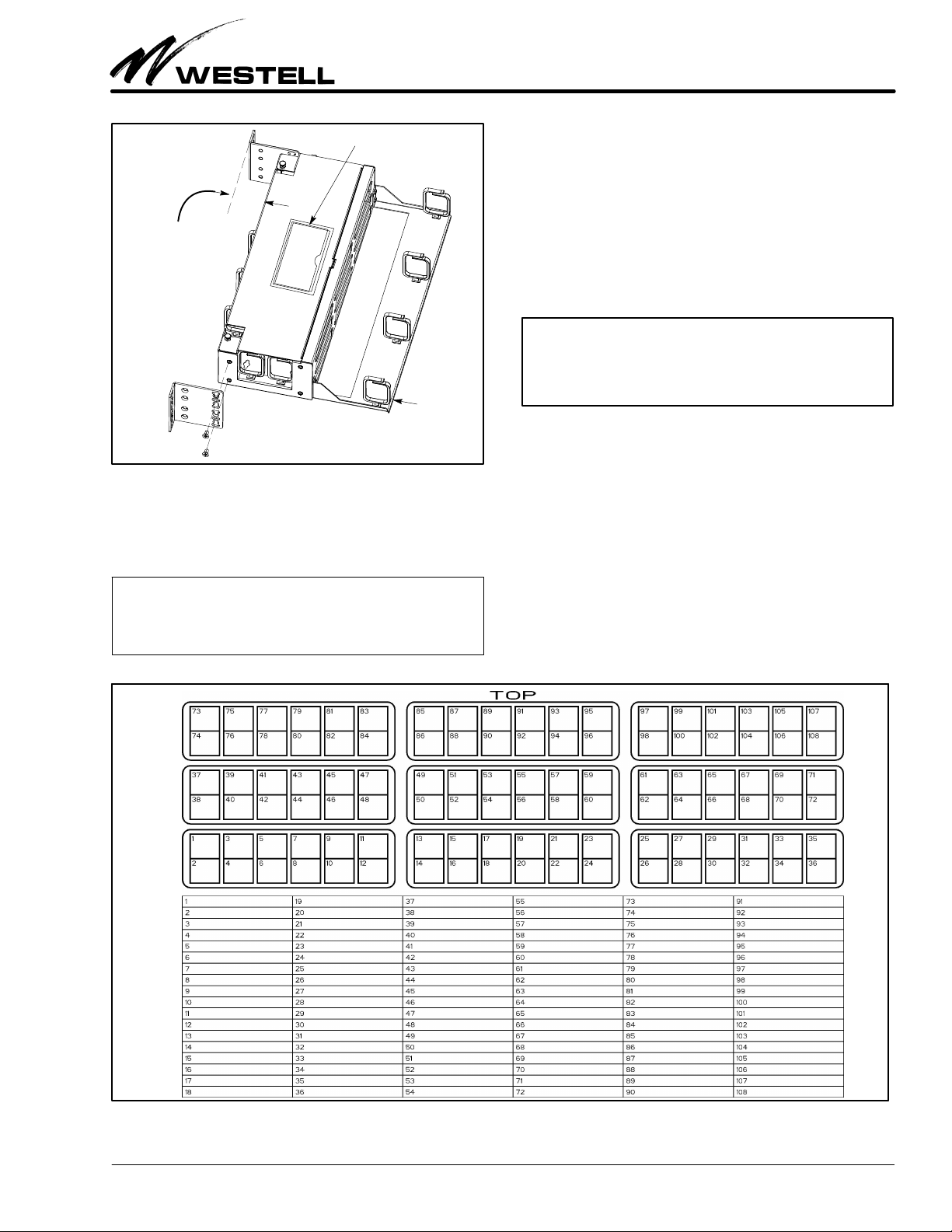
2.5.4 Labelling Circuit Positions
A circuit identification card (label) and a clear plastic packet
is provided for quick and easy circuit labelling and identifica
tion. Complete and fill in the card per company practice.
3 CUSTOMER & TECHNICAL SERVICES
3.1 Customer Service & Technical Assistance
If technical or customer assistance is required, contact Westell
by calling or using one of the following options:
Voice: (800) 377‐8766
email: [email protected]
For additional information about Westell, visit the Westell
World Wide Web site at http://www.Westell.com.
3.2 Part Numbers
This equipment is identified by a product number
(A90‐VELGX90), which consists of three parts: the issue letter
of the equipment (A), the assembly type (90), and the specific
model number (VELGX90). Each time a change is made to the
product which changes the form, fit, or function of the product,
the issue letter is incremented or advanced by one. Be sure to in
dicate the issue level as well as the model number when making
inquiries about the equipment.
4. WARRANTY & REPAIRS
4.1 Warranty
Westell warrants this product to be free of defects at the time of
shipment. Westell also warrants this product to be fully function
al for the time period specified by the terms and conditions
governing the sale of the product. Any attempt to repair or
modify the equipment by anyone other than an authorized Wes
tell representative will void the warranty.
4.2 Repair and Return
Westell will repair or replace any defective Westell equipment
without cost during the warranty period if the unit is defective
for any reason other than abuse, improper use, or improper
installation. To return defective equipment, first request a Re
turn Material Authorization (RMA) number from Westell by
calling or using one of the options shown below. Once an RMA
number is obtained, return the defective unit (freight prepaid),
along with a brief problem description, to the address we will
provide to you when you contact us.
Voice: (630) 375‐4457
email: [email protected]
Replacements will be shipped in the fastest manner consistent
with the urgency of the situation. Westell will continue to repair
or replace faulty equipment beyond the warranty period for a
nominal charge. Contact Westell for details.

Section VEL‐GX9‐20A
030‐300323 Rev. A
R
7
1406IARAD4c
Feature U.S. Metric
Height 3.47 inches (2 RUs) 8.81 cm
Width, w/o ears 16.8 inches (approx.) 42.67 cm
Width, w/ears in
19” rack position
19.325” (overall)
18.312” (mounting holes)
49.1 cm
46.5 cm
Width, w/ears in
23” rack position
23.525” (overall)
22.312” (mounting holes)
59.8 cm
56.7 cm
Depth, minimum 6.08 inches 15.44 cm
Depth, with tray, with
out rear clips/clamps
10.95 inches 27.81 cm
Weight 29 ounces 822 g
Operating Temp. ‐40to 149F ‐40to 65C
Humidity 0 to 95% (non‐condensing)
Table 2. Physical Specifications
5. SPECIFICATIONS
5.1 Physical Specifications
The physical specifications are shown in Table 2.
5.2 Ordering Specifications
To order units, call the telephone number shown in Paragraph
3.1 and please specify a specific part number shown in Table 3.
Part # Description
A90‐VELGX90 VirtualEdgerUniversal Connection Media Panel for LGX‐
type fiber cassettes/trays and/or LGX‐type fiber panels,
with 9 LGX‐sized positions, top cover, cable management
tray, and D‐rings. Rack/wall mountable (2 RUs high).
Orderable Options*
033-100045 Cable management ring, 1.38” x 1.73” (inside dimensions)
A90‐VE118LCU6 LGX‐type panel with 6 LC/UPC duplex couplers
A90-VE118SCU6 LGX‐type panel with 6 SC/UPC couplers
523‐700194 12-fiber LC/UPC stranded pigtail
523‐700202A 12-fiber LC/UPC ribbon pigtail
*A variety of cables and fiber jumpers also are available. Call Westell for details.
Table 3. Ordering and Option Information
This manual suits for next models
1
Table of contents
Popular Media Converter manuals by other brands

Absolute Process Instruments
Absolute Process Instruments DuoPak APD 2053 manual

Microchip Technology
Microchip Technology MCP2120 user guide

Data Translation
Data Translation DT3155 user manual

Ebyte
Ebyte ECAN-101 manual

KK Systems
KK Systems USB-485 Addendum to the Operation Manual

Crestron
Crestron UC-BRKT-200-S-T-ASSY manual

ADC
ADC OptEnet user manual

Transition Networks
Transition Networks E-PSW-FX-03(LH) user guide

Bang & Olufsen
Bang & Olufsen BeoCenter 9500 Setting-up guide

Harman Kardon
Harman Kardon FESTIVAL 60 Technical manual

Motrona
Motrona GV224 operating manual

TR-Electronic
TR-Electronic CEV582M 4096/4096 SSI 60ZB12N Series manual