(
'08
.5)
110
(
98
.&
)
too
;;
1
';;
(78.9)
eo
..
~
(59.2)
60
~
o
..
(
39
.
!0
)
40
(
19.7
)
20
o
NOTES
/
............
II "
f.-
I
./
./'
/ V
/ /
1---
/"
1000 1500
2000
2!>OO
3000
J
-
26
(
188
)
tl
~
25('8
1)
::I
24
(
'74
)
l:1
23
('66
)
~
22(
'59)
c:?
21
(
'52
)
~
~
"
z,
0"
~~
210
(
0.46
)
~
~
I
200
(0 .
44
)
~
';;1
u
~I
I
80
(0.
4'
) ;;l!:.
:J
::II
...
"
1. Cylinder
Head
:Special cast iron cylinder head precision-cast underthe
shell moulding process
and
so
ft
·gas-nitrided forincreased durability.
The
Intake and exhau
st
ports
are
arranged for crossllow
to
raise
intake
and
exhaust
efficiency. The swi
rl
type precombustion chamberisused.
2. Cylinder
Block
:
We
ight reduction achieved by technologies 01thin wall
du
ctile
cas
t iron and hatf ski
rt
.The water rail is designed to provide
uniform distribution
of
coolant
to
the cylinder head. The cylinder liner
IS
of
thedry type
of
high-phosphoruscast Iron, which IS givenspecial honing
10
provideqUickseating, goodall retention, thusIncreasing wear resistance.
3.
Crank
Mecha
nism:The crankshaft IS
01
the 7 bearings type. The piston
IS
of
la-Ex
alloywithovalskirtand
IS
eqUiPped with3compressed rings and
2 oil rings. The piston pin is offset by 1.5 mm for qUiet operatIOn.
4. Valve
Me
chanism:
OHVwlth
both theIntake and exhaustvalvesdesigned
to rotate to provide a longer lasung seal between valve and valve seat.
5. Intake
and
Exhaust System:The independent branch type intake
manifold is used to Increase Inlake efficiency.
Main
Specifications
Numberof Cylinders & Arrangement
..............
6 In·
Line
Cylinder Bore & Stroke
...............••..........
(3.62" x 4
")
Displacement
..
. . . . . . . . . .. .
..
4.
0521
(247.2 in')
Compression Ratio
..
.
......
••
••.......................
21
.0
Combustion Chamber
................
.
........
SwirlType
Firing Order
.....
.
.......••.......................
15 3 6 2 4
Rotating Direction
.......•
•
.........
Clockwise viewed from
Fan
Valve Arrangement
.......
...
......
..
.........
Overhead Valve
Injection Pump
........•.................
Bosch distributor type
Governor
..................
.
....
mechanical (Buill
in
Pump)
Lubrication Method
...........
.
..........
Pressure feed type
Cooling Method
.................
Fresh water by heat exchanger
Starling Aid System
........................
Glow Plug
Electrical System Voltage
..........
.
....
12
Volts
Dry Weight of engine
.......•
•••••
.
.....
....
(885Ibs
.)
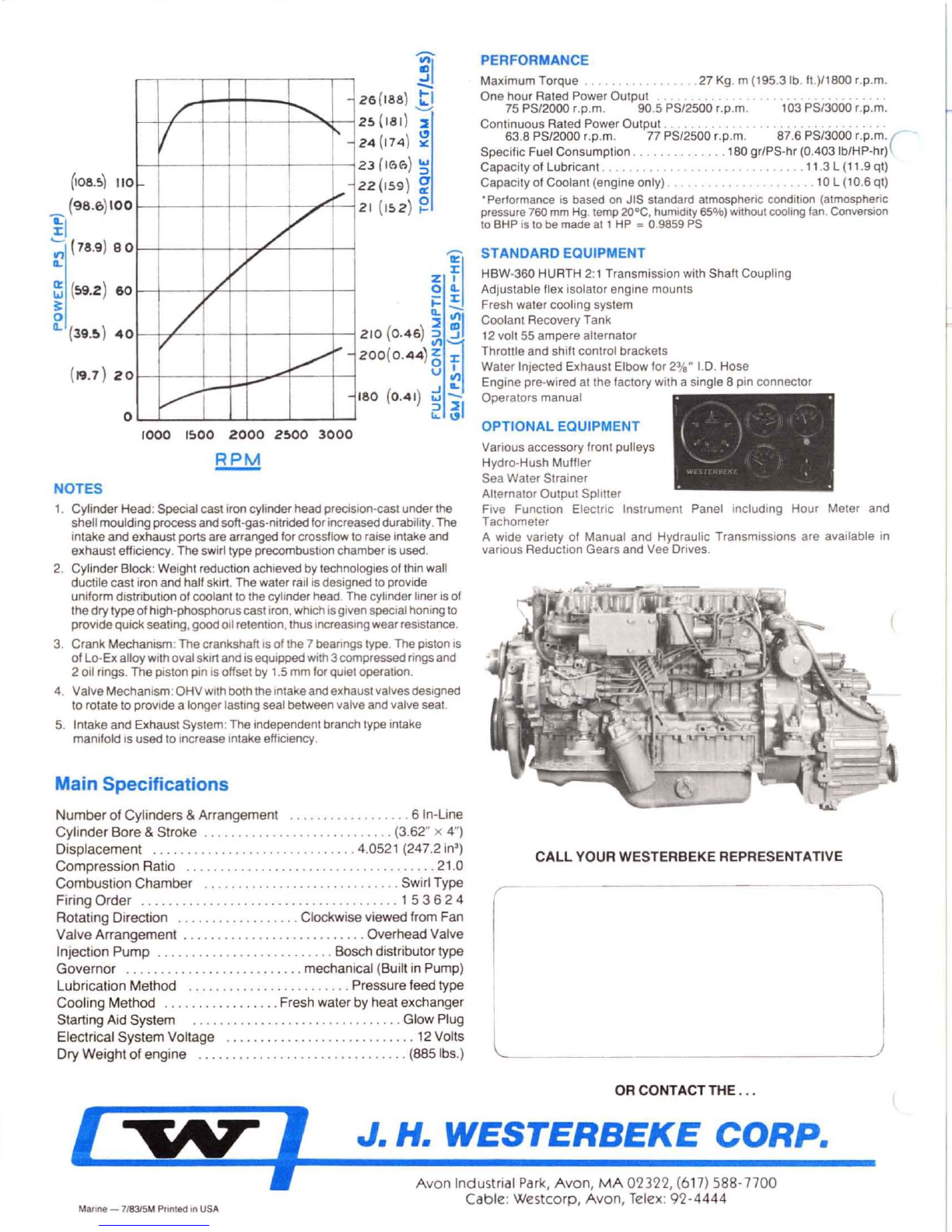
PERFORMANCE
Maxim
um
Torque
..
....
. . . . . .
..
27 Kg. m (195.3 lb. fl.)/18oo r.p.m.
One
hour
Rated
Power
Output
. . . . . . . . .
..
75
PS
/2
000 ,.p.
m.
90.5 PS/2500 '.p.m. 103 PS/3000 r.p.m.
Continuous
Rated Power
Output
. . . . . . . . . .
..
. . . .
...
63
.8
PS
/2000 ,.p.m: 77 PS/2500 r.p.m. 87.6
PS
/3000 '.p.m.(
SpeCIfic Fuel
Consumption
.............
.180
gr
/PS-
hr
(0.
403Ib
/HP-hr)
Capacity
of
Lubri
cant.
. . . . . . . . . .
.....
11.3 L (11.9 qt)
Capacity
of
Coolant(engine
only) . . . . . . . . . . . . 10 L (10.6
qt
)
•Perlormance is based
on
JIS standard atmospheric condition (atmospheric
pressure 760 mm
Hg
. temp
2O°C
, humidity 65%) without cooling Ian. Conversion
to
BHP is to
be
made at 1HP
""
0.9859 PS
STANDARD EQUIPMENT
HBW-360 HURTH 2:1 Transmission with Shaft Coupling
Adjustable flex isolator engine
mounts
Fresh water
cooling
system
Coolant Recovery Tank
12 volt 55
ampere
alternator
Throttle
and
shift control brackets
Water
Injected Exhaust Elbow for 23
/8"
1.0
.
Ho
se
Engine
pre-wired at the factory with a single 8
pin
connector
Operators
manual
OPTIONAL EQUIPMENT
Various accessory front pulleys
Hydro
-Hush Muffler
Sea
Water
Strainer
Alternator Output Splitter
Five Function ElectriC Instrument Panel
including
Hour
Meter and
Tachometer
A Wide vanety
01
Manual and Hydraulic Transmissions are available in
various Reduction Gears
and
Vee Drives.
CALL
YOUR WESTERBEKE REPRESENTATIVE
L
_____
___
OR
CONTACTTHE
...
J. H.
WESTERBEKE
CORP
.
Manne -
718315
M Pnnled
In
USA
A
von
Indu
strial
Park,
Avon
,
MA
02322,
(6
17
) 588·
7700
Cable
:
Westcorp,
Avon
, Telex:
92·4444


