Westermo RM-240 User manual

Wireless Ethernet
Radio Modem
www.westermo.com
©Westermo Teleindustri AB • 2007
Reference Guide
6193-5201
RM-240

26193-5201
Thank you for your selection of the RM-240 Wireless Ethernet Modem.
We trust it will give you many years of valuable service.

3
6193-5201
ATTENTION!
Incorrect termination of supply wires may
cause internal damage and will void warranty.
To ensure your RM-240 enjoys a long life,
double check ALL your connections with the users manual
before turning the power on.
Caution!
For continued protection against risk of fire, replace the internal module fuse only with
the same type and rating.
CAUTION:
To comply with FCC RF Exposure requirements in section 1.1310 of the FCC Rules,
antennas used with this device must be installed to provide a separation distance of at
least 20 cm from all persons to satisfy RF exposure compliance.
DO NOT:
… operate the transmitter when someone is within 20 cm of the antenna
… operate the transmitter unless all RF connectors are secure and any open connectors
are properly terminated.
… operate the equipment near electrical blasting caps or in an explosive atmosphere
All equipment must be properly grounded for safe operations.
All equipment should be serviced only by a qualified technician.

46193-5201
Important Notice
WESTERMO products are designed to be used in industrial environments, by experi-
enced industrial engineering personnel with adequate knowledge of safety design
considerations.
WESTERMO radio products are used on unprotected license-free radio bands with radio
noise and interference.The products are designed to operate in the presence of noise
and interference, however in an extreme case, radio noise and interference could
cause product operation delays or operation failure. Like all industrial electronic prod-
ucts,WESTERMO products can fail in a variety of modes due to misuse, age, or mal-
function.We recommend that users and designers design systems using design tech-
niques intended to prevent personal injury or damage during product operation, and
provide failure tolerant systems to prevent personal injury or damage in the event of
product failure. Designers must warn users of the equipment or systems if adequate
protection against failure has not been included in the system design. Designers must
include this Important Notice in operating procedures and system manuals.
These products should not be used in non-industrial applications, or life-support systems,
without consulting WESTERMO Technologies first.
1. A radio license is not required in some countries, provided the module is installed
using the aerial and equipment configuration described in the RM-240 Installation
Guide. Check with your local distributor for further information on regulations.
2. Operation is authorized by the radio frequency regulatory authority in your country
on a non-protection basis.Although all care is taken in the design of these units, there
is no responsibility taken for sources of external interference. Systems should be
designed to be tolerant of these operational delays.
3. To avoid the risk of electrocution, the aerial, aerial cable, serial cables and all terminals
of the RM-240 module should be electrically protected.To provide maximum surge
and lightning protection, the module should be connected to a suitable earth and the
aerial, aerial cable, serial cables and the module should be installed as recommended
in the Installation Guide.
4. To avoid accidents during maintenance or adjustment of remotely controlled equip-
ment, all equipment should be first disconnected from the RM-240 module during
these adjustments. Equipment should carry clear markings to indicate remote or auto-
matic operation. E.g. “This equipment is remotely controlled and may start without
warning. Isolate at the switchboard before attempting adjustments.”
5. The RM-240 module is not suitable for use in explosive environments without addi-
tional protection.

5
6193-5201
Chapter One INTRODUCTION
The RM-240 Industrial WiFi Wireless Ethernet module provides wireless connections
between Ethernet devices or Ethernet wired networks (LAN’s). It complies with the IEEE
802.11b standard.The RM-240 has an internal 2.4GHz direct sequence spread spectrum
(DSSS) wireless transceiver, which can be used without a radio license in most countries.
Users can select one of 11 x 5 MHz wide channels, with the first channel centred at
2.412 GHz.
Note that regulations in North America and part of Europe permit all 11 channels to be used
in these countries. Please check with your WESTERMO representative for the permitted channel
usage in your country.
The RM-240 unit also provides two serial connections as well as the Ethernet connec-
tions. It is possible to use all three data connections concurrently, allowing the RM-240
to act as a Device Server.Wireless connections can be made between serial devices and
Ethernet devices, however approriate driver applications are required in the host devices
to handle the different data format.The RM-240 does provide connection funtionality
between serial “Modbus RTU” devices and Ethernet “Modbus TCP” devices.
The RM-240 is available in two models with different RF power:
RM-240-100 100mW of RF power
RM-240-300 300mW of RF power
Note that European regulations do not permit more than 100mW of RF power to be used. In
USA, Canada and Australia, up to 1W of RF power may be generated. In other countries, please
check with your WESTERMO representative.
The RM-240 has a standard RJ45 Ethernet connection which will operate at up to
100Mbit/sec.The module will transmit the Ethernet messages on the wireless band at
rates between 1 and 11 Mbit/sec.

66193-5201
1.1 Network Topology
The RM-240 is an Ethernet device, and must be configured as part of an Ethernet net-
work. Each RM-240 must be configured as:
… an “Access Point” or a “Client”, and
… a “Bridge” or a “Router”.
You can also connect to the RM-240 via a
RS-232 or RS-485 serial port using PPP
(point-to-point) protocol. PPP allows the RM-240 to connect serial communications
into the Ethernet network.
Access Point vs Client
The Access Point unit acts as the
“wireless master” unit.The Access
Point sets up the wireless links
to the Client units, and controls
the wireless communications.The
first diagram shows two Ethernet
devices being linked. One RM-240
is configured as an Access Point
and one as a Client – in this example it doesn’t mater which unit
is the Access Point.
The second diagram shows an existing LAN being extended
using RM-240’s. In this example, the Access Point should be
configured at the LAN end – although the wireless link
will still work if the Client is at the LAN end.
An Access Point can connect to multiple Clients. In
this case, the Access Point should be the “central”
unit.
6XXZhh
Ed^ci
8a^Zci
:i]ZgcZi
9Zk^XZ
6XXZhh
Ed^ci
A6C
8a^Zci
:i]ZgcZi
9Zk^XZ
6XXZhh
Ed^ci
A6C
8a^Zci
8a^Zci
8a^Zci
:i]ZgcZi9Zk^XZ

7
6193-5201
An Access Point could be used as a “Repeater” unit to connect two RM-240 Clients
which do not have direct reliable radio paths.
Multiple Access Points can be set-up in a “mesh” network to provide multiple repeaters.
Bridge vs Router
Each RM-240 is config-
ured with an IP address
for the Ethernet side, and
another for the wireless
side.
A Bridge connects
devices within the same
Ethernet network – for example, extending an existing Ethernet LAN. For a Bridge, the IP
address for the wireless side is the same as the Ethernet side.
A Router connects devices
on different LAN’s.The IP
addresses for the Ethernet
and wireless sides are dif-
ferent.
In the above example, the wireless link is part of LAN A, with the Client unit acting as a
Router between LAN A and LAN B.Alternately, the Access Point could be configured as
a Router – the wireless link is then part of LAN B.
6XXZhh
Ed^ci
A6C 8a^Zci 8a^Zci
:i]ZgcZi9Zk^XZ
6XXZhhEd^ci
7g^Y\Z
A6C
8a^Zci
7g^Y\Z
&.'#&+-#%#() &.'#&+-#%#,'
&.'#&+-#%#() &.'#&+-#%#,'
6XXZhhEd^ci
7g^Y\Z
A6C6
8a^Zci
GdjiZg
&.'#&+-#%#() A6C7
&.'#&+-#%#&,
&.'#&+-#%#() &.'#&+-#%#,'
6XXZhhEd^ci
7g^Y\Z
A6C6
8a^Zci
GdjiZg
&.'#&+-#%#() A6C7
&.'#&+-#%#&,
&.'#&+-#%#*) &.'#&+-#%#*(

86193-5201
If more than two routers are required within the same radio network, then routing rules
may need to be configured (refer section “3.11 Routing Rules” for further details).There
is no limit to the number of Bridges in the same network – although there is a limit of
255 Client units linked to any one Access Point.
1.2 Getting Started Quickly
Most applications for the RM-240 require little configuration.The RM-240 has many
sophisticated features, however if you don’t require these features, this section will allow
you to configure the units quickly.
First, read Section 2,“Installation”.The RM-240 requires an antenna and a power supply.
… Power the RM-240 and make an Ethernet connection to your PC (for further infor-
mation on how to do this, refer to section 3.3)
… Set the RM-240 address settings as per section 3.4
… Save the configuration – the RM-240 is now ready to use.
Before installing the RM-240, bench test the system. It is a lot easier to locate problems
when the equipment is all together.
There are other configuration setting which may or may not improve the operation of
the system. For detail on these settings, refer to section 3.
6XXZhhEd^ci
7g^Y\Z
A6C6
8a^Zci
7g^Y\Z
&.'#&+-#%#()
A6C7
&+.#'*)#&%.#)%
&.'#&+-#%#()
&.'#&+-#%#,)
8a^Zci
GdjiZg
8a^Zci
GdjiZg
A6C8
&+.#'*)#&%'#&,
&.'#&+-#%#,(
&.'#&+-#%#,'
&.'#&+-#%#,'

9
6193-5201
Chapter Two INSTALLATION
2.1 General
The RM-240 module is suitable for DIN-rail mounting.Terminals will accept wires up to
2.5 sqmm (12 gauge) in size.
All connections to the module must be SELV. Normal 110-240V mains supply
should not be connected to any terminal of the RM-240 module. Refer to
Section 2.3 Power Supply.
Before installing a new system, it is preferable to bench test the complete system.
Configuration problems are easier to recognize when the system units are adjacent.
Following installation, the most common problem is poor communications caused by
incorrectly installed antennas, or radio interference on the same channel, or the radio
path being inadequate. If the radio path is a problem (ie path too long, or obstructions in
the way), then higher performance antennas or a higher mounting point for the antenna
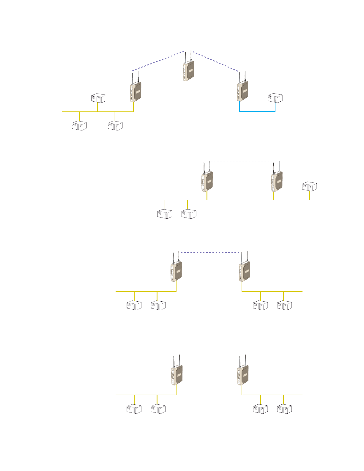
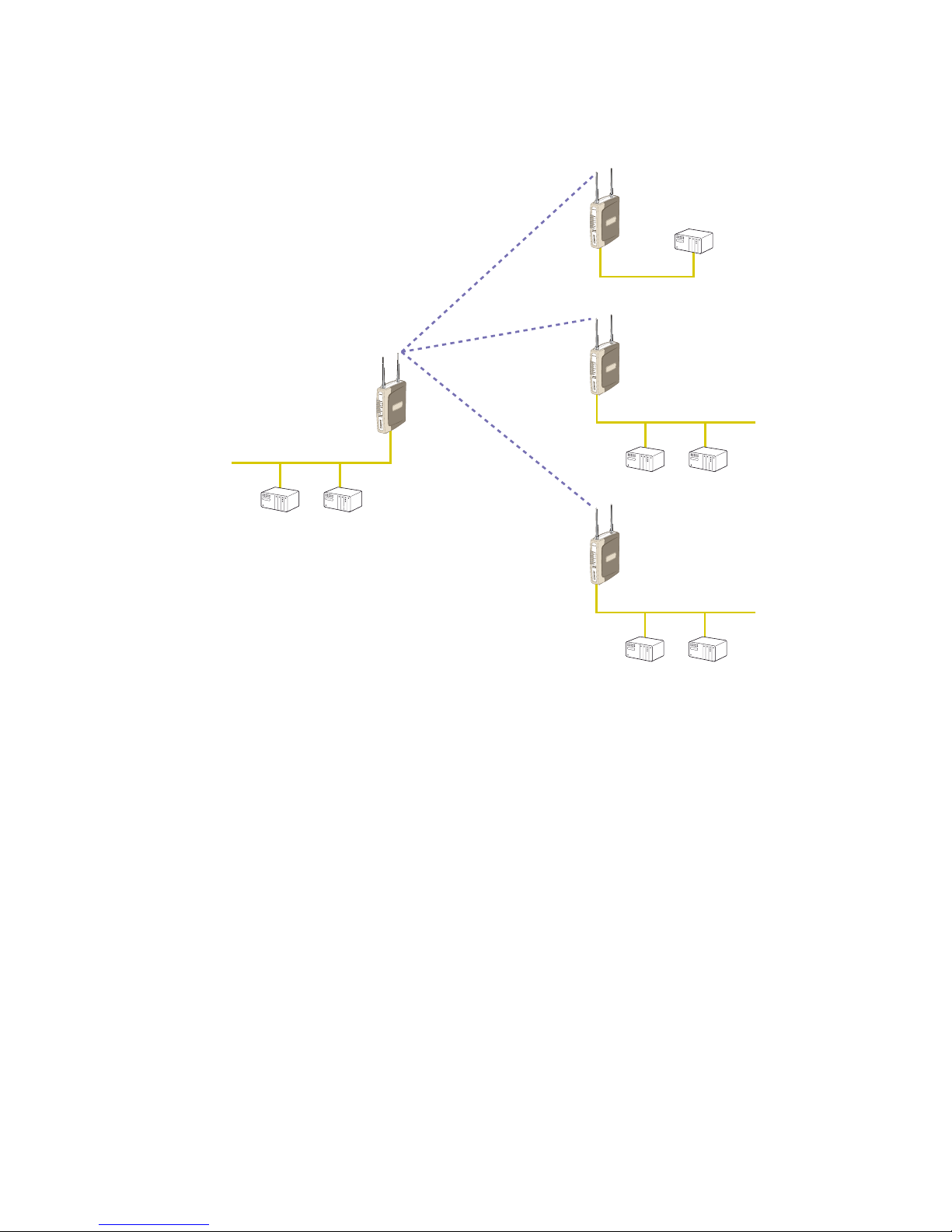
may rectify the problem.Alternately, use an intermediate RM-240 Module as a repeater.
Each RM-240 module should be effectively earthed via the “GND” terminal on the
RM-240 module – this is to ensure that the surge protection circuits inside the
RM-240 module are effective.
2.2 Antenna Installation
The RM-240 module will operate reliably over large distances.The distance which may be
reliably achieved will vary with each application – depending on the type and location of
antennas, the degree of radio interference, and obstructions (such as buildings or trees)
to the radio path.
The maximum range achievable depends on the regulated RF power permitted in your
country, and whether you use separate transmit and receive antennas.With a single
antenna, 5 km (3 miles) can be achieved in USA, Canada and Australia (4W ERP) and 1km
in Europe (100mW ERP).With separate transmit and receive antennas, more than 10km
(6 miles) can be achieved in USA, Canada and Australia and more than 5 km in Europe.
To achieve the maximum transmission distance, the antennas should be raised above
intermediate obstructions so the radio path is true “line of sight”.The modules will oper-
ate reliably with some obstruction of the radio path, although the reliable distance will
be reduced. Obstructions which are close to either antenna will have more of a block-
ing affect than obstructions in the middle of the radio path.The RM-240 modules pro-
vide a diagnostic feature which displays the radio signal strength of transmissions (refer
Diagnostics section).
Line-of-sight paths are only necessary to obtain the maximum range. Obstructions will
reduce the range, however may not prevent a reliable path.A larger amount of obstruc-
tion can be tolerated for shorter distances. For short distances, it is possible to mount
the antennas inside buildings.An obstructed path requires testing to determine if the path
will be reliable – refer the section 6 of this manual.

10 6193-5201
Where it is not possible to achieve reliable communications between two RM-240 mod-
ules, then a third RM-240 module may be used to receive the message and re-transmit it.
This module is referred to as a repeater.This module may also have a host device con-
nected to it.
The RM-240 unit has two antenna connections at the top of the module, allowing two
antennas to be fitted to the unit.The left connector (looking at the front) labeled “RX”
is connected only to the internal wireless receiver.The right connector labeled TX/RX is
connected to both the transmitter and receiver.
Note: when only one antenna is used, it must be connected to the right TX/RX connector.
Plant and factory installations
Most installations in industrial plants and factories use a single omni-directional antennas.
Installations can suffer from “multi-path fading” effects where multiple reflected radio
signals adversely affect the signal strength.This can be checked by moving the antenna
a short distance (10 cm or 4 inches) – if the signal increases significantly then there are
multi-path effects.
In a “static” installation, where the radio path is not changing, moving an antenna to the
position of maximum signal solves this problem. However where the radio path changes
because the RM-240 is mounted on moving equipment, or if there is moving equipment
in the area, then the solution is to use two antennas. Because the two connectors are
separated, the RF signal at each connector will be different in the presence of multi-path
fading.The RM-240 unit will automatically select the higher RF signal.
Note that directional antennas are not normally used in plant and factory installations.
Line-of-sight installations
In longer line-of-sight installations, the range may be increased by using a high gain
antenna on the TX/RX connector. However the gain should not cause the effective radi-
ated power (ERP) to exceed the permitted value. A second higher gain antenna can be
connected to the RX connector without affecting ERP – this will increase the operating
range provided the background noise in the area is low.
Antennas
Antennas can be either connected directly to the module connectors or connected via
50 ohm coaxial cable (eg RG58 Cellfoil or RG213) terminated with a male SMA coaxial
connector.The higher the antenna is mounted, the greater the transmission range will be,
however as the length of coaxial cable increases so do cable losses.
The net gain of an antenna/cable configuration is the gain of the antenna (in dBi) less the
loss in the coaxial cable (in dB).The maximum net gain of the antenna/cable configuration
connected to the TX/RX connector is 0dB in Europe (100mW ERP). In USA, Canada
and Australia (4W ERP), the maximum gain is 12dB for the RM-240-300 or 16dB for the
RM-240-100.There is no gain restriction for antennas connected to the RX connector.

11
6193-5201
The gains and losses of typical antennas are
Antenna Gain (dBi)
Dipole 2
Collinear 5 or 8
Directional 10 – 28
Cable type Loss (dB per 10 m / 30 ft)
RG58 Cellfoil -6
RG213 -5
LDF4-50 -1.5
The net gain of the antenna/cable configuration is determined by adding the antenna gain
and the cable loss. For example, a 5dBi antenna with 10 metres of Cellfoil has a net gain
of -1 dB (5dB – 6dB).
Installation tips
Connections between the antenna and coaxial cable should be carefully taped to prevent
ingress of moisture. Moisture ingress in the coaxial cable is a common cause for prob-
lems with radio systems, as it greatly increases the radio losses.We recommend that the
connection be taped, firstly with a layer of PVC Tape, then with a vulcanizing tape such as
“3M 23 tape”, and finally with another layer of PVC UV Stabilized insulating tape.The first
layer of tape allows the joint to be easily inspected when trouble shooting as the vulcan-
izing seal can be easily removed.
Where antennas are mounted on elevated masts, the masts should be effectively earthed
to avoid lightning surges. For high lightning risk areas, surge suppression devices between
the module and the antenna are recommended. If the antenna is not already shielded
from lightning strike by an adjacent earthed structure, a lightning rod may be installed
above the antenna to provide shielding.

12 6193-5201
2.2.1 Dipole and Collinear antennas.
A dipole or collinear antenna transmits the same amount of radio power in all directions
– as such that are easy to install and use.The dipole antenna with integral 5 metres
(15 feet) cable does not require any additional coaxial cable, however a cable must be
used with the collinear antennas.
Collinear and dipole antennas should be mounted vertically, preferably 30 cm (1 foot)
away from a wall or mast to obtain maximum range.
&bb^c^bjb
8DA>C:6G
6
CI:CC6
B6HI
:6GI=HI6@:
>;<GDJC98DC9>I>DCH6G:
EDDG!>CHI6AABDG:I=6C
>CHI6AA6:G>6A67DK:
AD86AD7HIGJ8I>DCH
6CI
GB"')%
HJG<:
6GG:HIDG
DEI>DC6A 8D6M>6A867A:
L:6I=:GEGDD;
8DCC:8IDGHL>I=
¹(B'(ºI6E:
HIG:HHG:A>:;ADDE
EGDK>9:<DD9
<GDJC9
8DCC:8I>DCID
B6HI !BD9JA:
6C9HJG<:
6GG:HIDG
<C9

13
6193-5201
2.2.2 Directional antennas.
Directional antennas can be
… a Yagi antenna with a main beam and orthogonal elements, or
… a directional radome, which is cylindrical in shape, or
… a parabolic antenna.
A directional antenna provides high gain in the forward direction, but lower gain in other
directions.This may be used to compensate for coaxial cable loss for installations with
marginal radio path.
Yagi antennas should be installed with the main beam horizontal, pointing in the forward
direction. If the Yagi is transmitting to a vertically mounted omni-directional antenna, then
the Yagi elements should be vertical. If the Yagi is transmitting to another Yagi, then the
elements at each end of the wireless link need to in the same plane (horizontal or verti-
cal).
Directional radomes should be installed with the central beam horizontal and must be
pointed exactly in the direction of transmission to benefit from the gain of the antenna.
Parabolic antennas should be mounted as per the manufacturer’s instructions, with the
parabolic grid at the “back” and the radiating element pointing in the direction of the
transmission.
Ensure that the antenna mounting bracket is well connected to “ground/earth”.
6
ciZccV^chiVaaZY
l
^i]YgV^c]daZh
Ydlc
8dVm[ZZYaddeZY
ViXdccZXi^dc
.%
d
GB"')%

14 6193-5201
2.3 Power Supply
The RM-240 module can be powered from a 9 – 30VDC power supply.The power sup-
ply should be rated at 1 Amp.The positive side of the supply must not be connected to
earth.The supply negative is connected to the unit case internally.The DC supply may be
a floating supply or negatively grounded.
The power requirements of the
RM-240 unit is 240mA @ 12V or
150mA @ 24VDC.This is inclu-
sive of radio and Ethernet ports
active, & serial port plugged in.
Transmission current is nominally
350mA at 12V (200mA at 24V) for
the 100mW RF unit, and 500mA
at 12V (350mA at 24V) for the 300mW RF unit.
A Ground Terminal is provided on the back of the module.This Terminal should be con-
nected to the Main Ground point of the installation in order to provide efficient surge
protection for the module (refer to the Installation Diagram)
2.4 Serial Connections
2.4.1 RS-232 Serial Port
The serial port is a 9 pin
DB9 female and provides for
connection to a host device
as well as a PC terminal
for configuration, field test-
ing and for factory testing.
Communication is via stand-
ard RS232 signals.
The RM-240 is configured as DCE equipment with the pinouts detailed below.
Hardware handshaking using the CTS/RTS lines is provided.The CTS/RTS lines may be
used to reflect the status of the local unit’s input buffer, or may be configured to reflect
the status of CTS/RTS lines at the remote site.The RM-240 does not support XON/
XOFF.
Example cable drawings for connection to a DTE host (a PC) or another DCE hosts (or
modem) are detailed above.
97.
B6A:
9I:=DHI
97.
;:B6A:
97.
B6A:
98:=DHI
97.
B6A:
G9
I9
H<
GIH
8IH
9HG
9IG
989
G9
I9
H<
GIH
8IH
9HG
9IG
989
G9
I9
H<
GIH
8IH
9HG
9IG
989
G9
I9
H<
GIH
8IH
9HG
9IG
989
'
(
*
,
-
'
(
*
,
-
+
)
&
'
(
*
,
-
'
(
*
,
-
+
)
&
GB"')% GB"')%
10-30
VDC

15
6193-5201
DB9 Connector Pinouts
Pin Name Direction Function
1 DCD Out Data carrier detect –
2RD Out Transmit Data – Serial Data Output
3TD In Receive Data – Serial Data Input
4 DTR In Data Terminal Ready –
5SG Signal Ground
6 DSR Out Data Set Ready – always high when unit is powered on.
7 RTS In Request to Send –
8 CTS Out Clear to send –
9RI Ring indicator –
2.4.2 RS-485 Serial Port
The RS-485 port provides for communication between the RM-240 unit and its host device
using a multi-drop cable. Up to 32 devices may be connected in each multi-drop network.
As the RS-485 communication medium is shared, only one of the units on the RS-485
cable may send data at any one time.Thus communication protocols based on the RS-485
standard require some type of arbitration.
RS-485 is a balanced, differential standard but it is recommended that shielded, twisted pair
cable be used to interconnect modules to reduce potential RFI. It is important to maintain
the polarity of the two RS-485 wires.An RS-485 network should be wired as indicated in
the diagram below and terminated at each end of the network with a 120 ohm resistor.
On-board 120 ohm resistors are provided and may be engaged by operating the single DIP
switch in the end plate next to the RS-485 terminals.The DIP switch should be in the “1”
or “on” position to connect the resistor. If the module is not at one end of the RS-485
cable, the switch should be off.
=DHI =DHI
GH")-*8dccZXi^dch
GB"')%

16 6193-5201
&'%
HJEEAN
GH"'('
9>EHL>I8=
;DG&'%
&'%
=DHI =DHI
GB"')%
:I=:GC:I
9>D
9:;6JAIH 9>E HL>I8=
GH")-*XdccZXi^dcjh^c\iZgb^cVi^c\gZh^hidg
GH")-*
100M
RUN
SETUP
LINK
(MDI X)
ETHERNET
(DCE)
ON
OFF
RS-485
RMINATION
RS-232 RS-485 COM+-T-T+ DTO
POWER

17
6193-5201
2.5 Discrete (Digital) Input/Output
The RM-240 has one on-board discrete/digital I/O channel.This channel can act as either
a discrete input or discrete output. It can be monitored, or set remotely, or alternatively
used to output a communications alarm status.
If used as an “input”, the I/O channel is suitable for voltage free contacts (such as
mechanical switches) or NPN transistor devices (such as electronic proximity switches).
PNP transistor devices are not suitable. Contact wetting current of approximately 5mA is
provided to maintain reliable operation of driving relays.
The digital input is connected between the ”DIO” terminal and common ”COM”.The
I/O circuit includes a LED indicator which is lit when the digital input is active, that is,
when the input circuit is closed. Provided the resistance of the switching device is less
than 200 ohms, the device will be able to activate the digital input.
The I/O channel may also be used as a discrete output.The digital outputs are transistor
switched DC signals, FET output to common rated at 30VDC 500 mA.
The output circuit is connected to the ”DIO” terminal.The digital output circuit includes
a LED indicator which is lit when the digital output is activ.
9>D
<C9 GB"')%
KdaiV
\
Z"[gZZ
XdciVXi^ceji
K
K
"
T
98
AdVY
BVm(%K98
%#*6
9>D
<C9 GB"')%

18 6193-5201
Chapter Three OPERATION
3.1 Start-up
“Access Point” Start-up
An Access Point unit starts and immediately begins transmitting periodic messages called
beacons.These beacon messages are messages contain information for Clients on how to
establish a link with the Access Point.
Any Client that hears the messages, which are not already linked to another Access Point
unit, will respond and links will be established between the new Access Point and these
Clients.
“Client” Start-up
When a Client powers up, it immediately scans for messages from Access Point units.The
Client will continue to scan for twice the configured beacon interval in the Client. During
the scan, the RX led will flicker now and again indicating messages received, perhaps from
an Access Point. If the Client finds suitable Access Points during the scan, it will then
attempt to establish a link with the Access Point with the strongest radio signal.
Link Establishment
When the Client wishes to establish a link with an Access Point it follows a two step
process.The first step is “authentication”. During this step the Client and Access Point
check if they can establish a secure link, based upon the configured security encryption.
Once the Client has been authenticated, it will then request a link.This step is called
“association”.
While no links have been established, the LINK led will be OFF. Once a single link has
been established, the LINK led is ON.
After the link is established, data may be transferred in both directions.The Access Point
will act as a master-unit and will control the flow of information to the Clients linked to
it.
The maximum number of 255 Clients may be linked to an Access Point.

19
6193-5201
How a Link connection is lost
The Access Point refreshes the link status with a Client every time a message is received
from that Client. If nothing is received from a Client for a period of 120 seconds, the
Access Point sends a “link-check” message. If there is no response to the link-check a
De-authenticate message is sent and the link is dropped.
A Client monitors beacons from an Access Point to determine whether the link is still
present. If the Client can no longer receive beacons from the AP, the AP is considered to
be out-of-range and the link is dropped.Whenever a Client is not connected to an AP, it
will cyclically scan all available channels for a suitable AP.
Roaming
Clients may also roam between Access Points. If a Client receives a beacon from an AP
with a stronger signal than the current AP (providing SSID is the same and capability
information are compatible), it may disconnect from the first AP and establish a link with
the second AP.This functionality permits a client to have mobility whilst maintaining a link
with the most suitable AP.
LED Indication
The following table details the status of the indicating LEDs on the front panel under
normal operating conditions.
LED Indicator Condition Meaning
OK GREEN Normal Operation
OK RED Supply voltage too low.
Radio RX GREEN flash Radio receiving data
Radio RX RED flash Weak radio signal
Radio TX Flash Radio Transmitting
Radio LINK On On when a radio communications link is established
Radio LINK Off Communications failure or radio link not established
Radio LINK GREEN flash
RED flash
Serial Port Receiving
CTS low
LAN ON Link Established on Ethernet port
LAN Flash Activity on Ethernet port.
Serial GREEN flash RS-232 Serial Port Activity
Serial RED flash RS-485 Serial Port Activity
DIO On Digital Output ON or Input is grounded.
DIO Off Digital Output OFF and Input is open circuit.
The Ethernet RJ45 port incorporates two indication LEDs.The LINK LED comes on
when there is a connection on the Ethernet port, and will blink off briefly when activity is
detected on the Ethernet Port.The 100MB LED indicates that the connection is at
100 MBit/Sec.The 100MB LED will be off for 10MB/Sec connection.
Other conditions indicating a fault are described in Chapter Six Troubleshooting.

20 6193-5201
3.2 Selecting a Channel
The RM-240 conforms to the IEEE 802.11 Wireless LAN specification.The RM-240 sup-
ports 11 radio channels, each 5MHz wide, in the range 2412MHz to 2462MHz. Only one
of these channels is used for a connection.The desired channel is selected and config-
ured at the Access Point, and is then used for all beacon transmissions and connections.
Clients scan all 11 channels for a suitable Access Point and then adopt the same channel
as the AP when a connection is established. Although each channel is only 5MHz wide,
the radio transmission is a lot wider. Hence the channels overlap.The following diagram
shows the RF energy distribution for a WiFi transmission:
Most of the energy is in a central 22 MHz wide “lobe”, centred around the channel fre-
quency, however there are also side-lobes extending either side.
If we ignore the side lobes and consider each WiFi message as a 22MHz wide transmis-
sion, then the following diagram represents how transmissions in each channel overlaps.
If there is more than one WiFi AP within the same wireless range, then it is important
that the AP’s are on channels as far apart as possible. If there are only two AP’s, then set
them to 1 and 11. If there are three, set them to 1, 6, 11.
It is also important that correct channel is selected for region. Channels 1 to 11 are
approved for North America (FCC), Europe (ETSI), Canada (IC) and Australia (ACMA).
Channels 10 and 11 are approved for use in Spain and France. Refer to the relevant regu-
latory authority for the region as to which radio channels are approved for use.
f-33 f-22 f-11 f f+11 f+22 f+33
RF power distribution in a WiFi transmission with channel central frequency,
Table of contents