Western Co WRM30 User manual

WRM30 Manuale installazione
Rev.
1.3
11-11-2014
This document is the property of WESTERN CO. Srl - All rights are reserved - Reproduction and use of information contained within this document is forbidden without the written consent of WESTERN CO. Srl
1
REGOLATORE PER LA CARICA DI BATTERIE DA MODULO FOTOVOLTAICO
WRM30
Il WRM30 è un regolatore per la carica di batterie da modulo fotovoltaico da
impiegare in grandi impianti ad isola. E’ adatto per sistemi a 12 /24 /48 e
può gestire una potenza fotovoltaica fino a 1,5/1,8kW.
Il WRM30 è specificatamente progettato per applicazioni industriali quali
alimentazioni di ponti radio/T , segnaletica stradale, o alimentazione di intere
abitazione completamente stand-alone.
Questo modello di regolatore di carica implementa un circuito di ricerca della
massima potenza di pannello (MPPT): indipendentemente dalla tensione di
batteria e dal suo stato di carica, il regolatore fa lavorare sempre il modulo P
nel suo punto di massima potenza massimizzando l’energia estratta dal
modulo e caricata in batteria. La ricarica è compensata in temperatura.
Particolarità di questo prodotto è la presenza di due canali distinti di ricarica e
quindi un doppio ingresso per i moduli P . Ciò permette la gestione di due
stringhe indipendenti, ad esempio nel caso siano composte da moduli con
caratteristiche diverse o esposti su due falde, oppure, con stringhe identiche, i
canali possono essere parallelati ottimizzando al massimo l’efficienza.
L’uscita carico può essere attivata secondo numerosi programmi selezionabili
dall’utente: carico acceso 24h/24h, carico acceso solo di giorno, carico acceso
solo di notte e carico acceso solo di notte per un numero di ore compreso da 1
a 16. Il WRM30 rileva lo stato giorno/notte in base alla tensione di pannello,
quindi non è necessario collegare ulteriori sensori al regolatore.
E’ dotato di una interfaccia seriale RS485 attraverso la quale è possibile
accedere a tutte le funzionalità disponibili.
Caratteristiche:
•Tensione di batteria 12V / 24V e 48V
•Autodetect 12V / 24V / 48V.
•Ricarica tipo MPPT
•Massima corrente di ricarica 3 A
•Per batterie Pb ermetiche/GEL, acido
libero e agli ioni di Litio (da rev. 1.1 )
•Tensione di ricarica compensata in
temperatura
•Diodo di blocco integrato
•Max potenza moduli PV 45 W@12V /
9 W@24V / 18 W@48V.
•Max tensione Voc sui moduli PV 15 V.
•Doppio ingresso moduli PV
•Parametri configurabili attraverso due
tasti e LCD
•18 programmi per gestione carico
•Max corrente di carico 15A.
•Protezione batteria scarica
•Protezione sovra-temperatura
•Protezione inversione polarità batteria
•Protezione sovraccarico su uscita
•Interfaccia RS485
•Contenitore metallico IP2
•Morsetti per cavi batteria 35mmq
•Morsetti per cavi moduli PV 1 mmq
•Morsetti per cavi carico 4mmq

WRM30 Manuale installazione
Rev.
1.3
11-11-2014
This document is the property of WESTERN CO. Srl - All rights are reserved - Reproduction and use of information contained within this document is forbidden without the written consent of WESTERN CO. Srl
2
Descrizione gener le
Il WRM30 è un regolatore di carica da moduli fotovoltaici per batterie elettrochimiche al piombo di tipo ermetico (SEAL)
o ad acido libero (FLOOD). Dalla rev 1.1 è stato introdotto un programma per la carica di batterie agli ioni di litio del tipo
che hanno integrato il BMS (Battery Management System); consigliamo di contattare la WesternCo per la scelta della
batteria agli ioni di Litio da collegare al WRM30. E’ assolutamente vietato collegare al WRM30 batterie al litio che non
hanno BMS integrato, infatti il BMS protegge la batteria da condizioni di funzionamento anomalo che potrebbero
portare all’incendio della batteria stessa. Collegando al WRM30 batterie non dotate di BMS si rischia l’incendio della
batteria. In fig. 1 è riportato uno schema di principio del WRM30.
Fig. 1 Schema di principio
1- Circuito di ricarica: costituito da due canali identici ma distinti, adatta la PAN e la IPAN (rispettivamente tensione e
corrente del modulo fotovoltaico) in modo da ricercare la condizione in cui la potenza erogata dal modulo P è
massima, realizzando quello che nella letteratura tecnica è indicato con la sigla MPPT (Maximum Power Point
Tracking). Inoltre gestisce la ricarica della batteria riducendo la corrente erogata verso la batteria nelle condizioni in
cui la tensione
batt
eguagli la sua tensione di ricarica
EoC.
2- Parallelo/Indipendente: questo collegamento
1
esterno va inserito quando si ha un campo fotovoltaico unico oppure
separato ma su un’unica falda. Con il ponte esterno il regolatore vede un unico campo fotovoltaico e ripartisce la
potenza equamente tra i due canali. In un impianto con due falde o comunque laddove si voglia mantenere i canali
indipendenti il ponte non va inserito e il regolatore ricercherà due MPPT differenti
2
.
3- Protezioni: Gli interruttori fungono da protezione antiinversione batteria e da diodo di blocco, essi evitano che
durante la notte, quando il modulo fotovoltaico non è illuminato questo possa assorbire corrente dalla batteria. I
fusibili interni garantiscono un ulteriore grado di protezione.
4- Carico: Il carico
3
è alimentato con la stessa tensione di batteria ed è controllato attraverso un interruttore a
semiconduttore.
5- Microprocessore: controlla l’intero circuito; misura correnti e tensioni dei moduli P , della batteria e del carico, e le
visualizza sul display.
6- Per una più precisa rilevazione della tensione e temperatura di batteria il WRM30 utilizza un sensore da posizionare
vicino ai morsetti di batteria (il sensore è fornito in dotazione: SPC20.S). E’ importante connettere questo sensore
per garantire la compensazione in temperatura della tensione di fine carica del sistema (
EoC
) e per una misura della
tensione di batteria indipendente dalla caduta di tensione sui cavi. Qualora non si connetta questo sensore il sistema
funzionerà ugualmente, ma la tensione di batteria sarà misurata sui morsetti interni del WRM30, mentre la
compensazione della
EoC
in funzione della temperatura non sarà eseguita e prudenzialmente la
EoC
sarà impostata
al valore minimo, come se il sistema rilevasse una temperatura di 60°C.
1
2
5
4
3
6

WRM30 Manuale installazione
Rev.
1.3
11-11-2014
This document is the property of WESTERN CO. Srl - All rights are reserved - Reproduction and use of information contained within this document is forbidden without the written consent of WESTERN CO. Srl
3
Il WRM30 ha una riconoscimento automatico della tensione di batteria eseguito all’accensione, di conseguenza imposta
i parametri di ricarica appropriati come descritto in tab. 1.
Tensione di b tteri misur t ll’ vvio Tensione nomin le rilev t
10.0 <
batt
< 16.0
Batteria a 12
20.0 <
batt
< 32.0
Batteria a 24
40.0 <
batt
< 64.0
Batteria a 48
Tab. 1 Soglie riconoscimento tensione nominale batteria
Qualora la tensione di batteria non rientri in un delle fasce in tab. 1 il WRM30 segnalerà l’errore E03 (vedi §
All rmi e
errori del sistem
), la ricarica e il carico saranno disattivati. In caso compaia questo errore controllare la corretta tensione
del banco batterie quindi rieseguire l’avvio.
1
Il ponte va realizzato con un conduttore di sezione di almeno 2,5mm
2
.
2
Attenzione a non superare la PchMax per ciascun canale.
3
Il carico ha il morsetto positivo in comune con il positivo di batteria mentre il meno è commutato tramite l’interruttore interno. (non collegare mai il meno del
carico con il meno di batteria!)
Scelt del modulo fotovolt ico
Il regolatore di carica WRM30, grazie al circuito di ricarica con MPPT, permette di impiegare un’ampia gamma di moduli
fotovoltaici garantendo lo sfruttamento ottimale di tutta la potenza. Il modulo P va scelto a seconda della tensione
nominale della batteria e rispettando i vincoli dell’ingresso pannello del WRM30. La tab. 2 sottostante da un’indicazione
dei range consigliati accettati in ingresso su ciascun canale P del regolatore.
Tensione nominale batteria
Caratteristiche stringhe PV
@25°C
(per canale) Range
12V
mp
: tensione alla massima potenza
OC
: tensione circuito aperto
P
MAX
: massima potenza
N
cs
: numero di celle in serie
1
15,0
≤
mp
≤
3
0
<40
< 225W
36≤ N
cs
≤60
24V
mp
: tensio
ne alla massima potenza
OC
: tensione circuito aperto
P
MAX
: massima potenza
N
cs
: numero di celle in serie
1
30
,0
≤
mp
≤
60
<80
< 450W
72≤ N
cs
≤112
48V
mp
: tensione alla massima potenza
OC
: tensione circuito aperto
P
MAX
: massima potenza
N
cs
: numero di celle in serie
1
60
,
0
≤
mp
≤
120
<140
< 900W
144≤ N
cs
≤168
Tab. 2 Selezione stringhe PV
1
alori riferiti a moduli al silicio mono o poli cristallino.
Installazione
1) Installare il WRM30 in un luogo asciutto ed adeguatamente arieggiato, fissato su di una superficie non infiammabile
e posizionato in modo da lasciare uno spazio privo di ostacoli di almeno 10cm nell’intorno del dispositivo che ne
permette il raffreddamento per convezione naturale dell’aria o forzata tramite la ventola interna.
2) Rimuovere lo sportello anteriore per accedere alle connessioni elettriche (vedi fig. ).
3) Collegare nell’ordine: carico, sonda per misura temperatura e tensione batteria (in dotazione), modulo P , e per
ultimo la batteria come nello schema fig. 2. Alla connessione della batteria il regolatore si accende e inizia a
funzionare. Le sezioni di cavo debbono essere scelte in modo che in ogni tratto di cavo la massima caduta di tensione
ammessa sia minore del 3% della tensione nominale del sistema. (Tab. 3)
4) Si possono collegare al WRM30 batterie al piombo con tensione nominale 12 , 24 oppure 48 . All’accensione il
regolatore misura la tensione di batteria, riconosce la tensione nominale del banco batteria ad esso connesso e
imposta automaticamente i corretti livelli di tensione di ricarica (vedi §
Descrizione gener le
). L’utente deve però
configurare il tipo di batteria in uso per adeguare la corretta tensione di ricarica (
EoC
). Si deve impostare la
configurazione SEAL se si usano batteria ermetiche RLA o di tipo GEL, mentre si deve scegliere la configurazione
FLOOD se si usano batterie ad acido libero. (vedi §
Configur zione del sistem
)

WRM30 Manuale installazione
Rev.
1.3
11-11-2014
This document is the property of WESTERN CO. Srl - All rights are reserved - Reproduction and use of information contained within this document is forbidden without the written consent of WESTERN CO. Srl
4
5) Impostare il programma di gestione del carico adeguato alla propria applicazione. Nota: non collegare all’uscita LOAD
carichi che assorbono una corrente superiore a 15A, altrimenti il sistema va in protezione per sovracorrente (
E02
) e il
carico non viene alimentato.
6) Montare i ferma-cavo in dotazione in modo che il peso dei cavi
1
non sia scaricato sui morsetti elettrici, ma sul ferma-
cavo stesso e montare lo sportello anteriore a protezione delle connessioni elettriche.
1
Per i cavi carico e sonda di batteria non ci sono dei fermacavo specifici, occorre ancorarli con delle fascette serracavo su quelli di batteria.
Schem di colleg mento
Sezioni coppie di cavo in rame raccomandate che
garantiscono una caduta di tensione massima pari al 3% della
tensione nominale della batteria
.
Max. distanza
per coppia [m]
@ 12V
Sezione c vi
6
mm
2
10
mm
2
16
mm
2
25
mm
2
32 mm
2
Current
10A 6,3 10,5 16,7 26,2 33,5
20A 3,1 5,2 8,4 13,1 16,7
30A 2,1 3,5 5,6 8,7 11,2
Max. distanza
per coppia [m]
@ 24V
Sezione c vi
6
mm
2
10
mm
2
16
mm
2
25
mm
2
32 mm
2
Current
10A 6,3 10,5 16,7 26,2 33,5
20A 3,1 5,2 8,4 13,1 16,7
30A 2,1 3,5 5,6 8,7 11,2
Max. distanza
per coppia [m]
@ 48V
Sezione c vi
6
mm
2
10
mm
2
16
mm
2
25
mm
2
32 mm
2
Current
10° 6,3 10,5 16,7 26,2 33,5
20A 3,1 5,2 8,4 13,1 16,7
30A 2,1 3,5 5,6 8,7 11,2
Tab. 3 Scelta sezione cavi
Fig. 2 Schema di collegamento
Coll udo dell’impi nto
Appena realizzati i collegamenti come in fig. 3 è necessario procedere al collaudo del sistema.
1- All’accensione il display indicherà temporaneamente la revisione del firmware (vedi § Configurazione del sistema
punto 1) e subito dopo una videata che indicherà la tensione nominale del sistema rilevata (vedi §
Visu lizz zioni
punto 1-b). Assicurarsi che la tensione letta corrisponda a quella del sistema. La visualizzazione della tensione
nominale del sistema può essere ripetuta (vedi §
Visu lizz zioni
punto 1-b).
rif. P
ag
.
2
punto (2)

WRM30 Manuale installazione
Rev.
1.3
11-11-2014
This document is the property of WESTERN CO. Srl - All rights are reserved - Reproduction and use of information contained within this document is forbidden without the written consent of WESTERN CO. Srl
5
2- erificare che nella pagina principale o in quella dedicata alla lettura della temperatura di batteria (vedi §
Visu lizz zioni
punto 5), non lampeggino l’icona batteria e il simbolo ‘°C’, ciò ad indicare il corretto collegamento della
sonda di tensione e temperatura di batteria.
3- Con il modulo P esposto al sole, verificare che il WRM30 ricarichi la batteria andando a leggere la corrente di
ricarica I
chA
+ I
chB
(vedi §
Visu lizz zioni
punto 2).
4- erificare la corretta accensione del carico. Se il carico è acceso solo di notte è possibile simulare la notte
scollegando temporaneamente uno dei fili del modulo P . Oppure impostando temporaneamente la
programmazione del carico a 24h/24h, (vedi §
Configur zione del sistem
punto 5).
5- erificare con il carico acceso la corrente da questo assorbita leggendo il parametro I
LOAD
nell’apposita pagina
dell’LCD (vedi §
Visu lizz zioni
punto 7).
ATTENZIONE:
Lo spegnimento del sistema deve avvenire con la seguente sequenza
:
1) Disconnessione moduli PV
2) Attesa (~3 sec.) fino a che sul display scompaia l’animazione dentro l’icona di batteria (fig. 3 - indicatore
corrente di ricarica)
3) Disconnessione batteria
Non rispettare la suddetta sequenza potrebbe portare ad un danneggiamento del WRM3 .
Visu lizz zioni
Il WRM30 è dotato di un display e due tasti per l’interfaccia utente, è organizzato in due ambienti: uno di visualizzazione
e uno di configurazione, nel primo è presente una videata principale dove sono sintetizzate le informazioni più
importanti del sistema, poi altre videate principali mostrano nel dettaglio altre grandezze. L’altro ambiente è quello di
configurazione dove vengono impostati i parametri di funzionamento del sistema. Le varie sequenze sono dettagliate
nelle tabelle successive, su quelle di visualizzazione alcune sono raggruppate (cornice e sfondo diverso) in quanto sono
logicamente unite tra loro da un riferimento comune: grandezze riferite ad entrambi i canali, alla temperatura, al carico,
al canale A e al canale B.
Stato gio rno/notte
I n config urazione
Pr otezione batteria scarica
Stato
carico
Pr ogramm a di rica rica
Visualizzatore mi su re inte rne
Ind icatore co rrente carico
I ndi catore corre nte modulo PV
Ind icatore corr ente in ricarica
Fig. 3 Display
SEQUENZA PAGINE DI VISUALIZZAZIONE STATO E PARAMETRI
1
1-a
1-b
P gin princip le.
isualizza la tensione di batteria (
BAT
), il programma di ricarica attualmente selezionato (SEAL, FLOOD o nulla se Litio), lo
stato giorno/notte rilevato dal modulo P , l’icona dello stato carico, se accesa, indica che il carico è alimentato, infine
l’allarme di batteria scarica. L’animazione
1
delle barre indica presenza di corrente rispettivamente: dal modulo P , in
ricarica, e verso il carico.
Premendo questo tasto compare temporaneamente la tensione di fine carica corrente (è funzione della temperatura
di batteria rilevata), evidenziata dalla scritta “EoC” e di seguito il valore in olt.
Mantenendo premuto per 1 sec. questo tasto compare temporaneamente la tensione nominale del sistema (12 /
24 / 48 ), evidenziata dalla scritta “SYS” e di seguito il valore in olt. Qui è anche visualizzata l’indicazione di utilizzo della
tensione di batteria locale (due barre vicine al simbolo batteria) oppure remota (due barre lontane al simbolo batteria)

WRM30 Manuale installazione
Rev.
1.3
11-11-2014
This document is the property of WESTERN CO. Srl - All rights are reserved - Reproduction and use of information contained within this document is forbidden without the written consent of WESTERN CO. Srl
6
2
2-a
Visu lizz l corrente tot le di ric ric di entr mbi i c n li (I
chA+
I
chB
).
R
imangono le altre indicazioni della pagina principale
con la sola animazione della corrente in ricarica.
Premendo questo tasto compare temporaneamente il riferimento ai canali visualizzati: in questo caso “cAb” cioè la
grandezza è relativa ad entrambi i canali A+B.
3
Visu lizz l potenz tot le di ric ric di entr mbi i c n li (P
chA+
P
chB
).
Rimangono le altre indicazioni della pagina principale
con la sola animazione della corrente in ricarica.
Premendo questo tasto compare temporaneamente il riferimento ai canali visualizzati: in questo caso “cAb” cioè la
grandezza è relativa ad entrambi i canali A+B.
4
Visu lizz il cont tore dell’energi tot le di ric ric di entr mbi i c n li (E
chA+EchB
).
Rimangono le altre indicazioni della
pagina principale con la sola animazione della corrente in ricarica.
Premendo questo tasto compare temporaneamente il riferimento ai canali visualizzati: in questo caso “cAb” cioè la
grandezza è relativa ad entrambi i canali A+B.
Mantenendo premuto per 1 sec. questo tasto viene azzerato questo contatore di energia.
5
Visu lizz l temper tur di b tteri rilev t d ll sond estern (T
BAT
).
Rimangono le altre indicazioni della pagina
principale tranne le animazioni. Un lampeggio dell’icona della batteria e simbolo “°C” indicano l’assenza della sonda di
temperatura remota
2
.
6
Visu lizz l temper tur rilev t d ll sond intern l WRM30 (T
INT
).
Rimangono le indicazioni delle icone giorno/notte,
stato carico e allarme batteria scarica.
7
Visu lizz l corrente ssorbit d l c rico (I
LOAD
).
Rimangono le altre indicazioni della pagina principale con la sola
animazione della corrente del carico.
8
Visu lizz l potenz ssorbit d l c rico (P
LOAD
).
Rimangono le al
tre indicazioni della pagina principale con la sola
animazione della corrente del carico.
9
Visu lizz il cont tore dell’energi ssorbit d l c rico (E
LOAD
).
Rimangono le altre indicazioni della pagina principale con la
sola animazione della corrente del carico.
Mantenendo premuto per 1 sec. questo tasto viene azzerato questo contatore di energia.
10
10-a
Visu lizz l tensione sul modulo del c n le A (V
chA
).
Rimangono le altre indicazioni della pagina principale con la sola
animazione della corrente del modulo P .
Premendo questo tasto compare temporaneamente il riferimento al canale visualizzato: in questo caso “cA” cioè la
grandezza è relativa al canale A.
11
Visu lizz l corrente
3
erog t d l singolo modulo
del c n le A (I
chA
).
Rimangono le altre indicazioni della pagina principale
tranne l’animazione della corrente del modulo P .
Premendo questo tasto compare temporaneamente il riferimento al canale visualizzato: in questo caso “cA” cioè la
grandezza è relativa al canale A.
12
Visu lizz l
potenz
3
de
l modulo del c n le A (P
chA
).
Rimangono le altre indicazioni della pagina principale con la sola
animazione della corrente del modulo P .
Premendo questo tasto compare temporaneamente il riferimento al canale visualizzato: in questo caso “cA” cioè la
grandezza è relativa al canale A.

WRM30 Manuale installazione
Rev.
1.3
11-11-2014
This document is the property of WESTERN CO. Srl - All rights are reserved - Reproduction and use of information contained within this document is forbidden without the written consent of WESTERN CO. Srl
7
13
Visu lizz il cont tore di energi fornit d l modulo del c n le A (E
chA
).
Rimangono le altre indicazioni della pagina
principale con la sola animazione della corrente del modulo P .
Premendo questo tasto compare temporaneamente il riferimento al canale visualizzato: in questo caso “cA” cioè la
grandezza è relativa al canale A.
Mantenendo premuto per 1 sec. questo tasto viene azzerato questo contatore di energia.
14
14-a
Visu lizz l tensione sul modulo del c n le B (V
chB
).
Rimangono le altre indicazioni della pagina principale con la sola
animazione della corrente del modulo P .
Premendo questo tasto compare temporaneamente il riferimento al canale visualizzato: in questo caso “c b” cioè la
grandezza è relativa al canale B.
15
Visu lizz l corrente
3
erog t d l singolo modulo del c n le B (I
chB
).
Rimangono le altre indicazioni della pagina principale
tranne l’animazione della corrente del modulo P .
Premendo questo tasto compare temporaneamente il riferimento al canale visualizzato: in questo caso “c b” cioè la
grandezza è relativa al canale B.
16
Visu lizz l
potenz
3
del
modulo del c n le B (P
chB
).
Rimangon
o le altre indicazioni della pagina principale con la sola
animazione della corrente del modulo P .
Premendo questo tasto compare temporaneamente il riferimento al canale visualizzato: in questo caso “c b” cioè la
grandezza è relativa al canale B.
17
Visu lizz il cont tore di energi fornit d l modulo del c n le B (E
chB
).
Rimangono le altre indicazioni della pagina
principale con la sola animazione della corrente del modulo P .
Premendo questo tasto compare temporaneamente il riferimento al canale visualizzato: in questo caso “c b” cioè la
grandezza è relativa al canale B.
Mantenendo premuto per 1 sec. questo tasto viene azzerato questo contatore di energia.
Da questa pagina, premendo questo tasto si ritorna alla pagina principale.
- Mantenendo premuto per 1 sec. questo tasto si ritorna alla pagina principale da qualsiasi pagina.
- Se non viene premuto nessun tasto per 2 minuti ritorna automaticamente alla pagina principale da qualsiasi pagina, vale
anche nell’ambiente di Configurazione (vedi paragrafo successivo).
1
Le animazioni sulla prima pagina compaiono nei seguenti casi: l’animazione corrente di pannello solo se è giorno, l’animazione corrente in ricarica solo se la ricarica
è attiva, l’animazione corrente Load solo se l’uscita è attiva.
2
Questa informazione è riportata anche sulla prima pagina ma con una frequenza di lampeggio minore
.
3
La corrente e la potenza del modulo per ciascun canale (I
chX
) non è misurata direttamente ma è ricalcolata internamente.
Configur zione del sistem
P
unt
o
SEQUENZA PAGINE DI CONFIGURAZIONE SISTEMA
Mantenendo premuti per 1 sec. questi tasti da qualsiasi pagina di visualizzazione si accede alle pagine di configurazione.
1
Visu lizz l revisione del firmw re del regol tore.
Mantenendo premuto per 1 sec. questo tasto vengono azzerati i contatori interni di: NCicli
1
, NLowBatt
1
,
NOverLoad
1
, NOverTemp
1
, ContaOre
1
(tranne i contatori di energia)
2
Impost l tensione di ric ric per l b tteri .
Le tensione visualizzata si riferisce alla tensione di fine carica a 25°C.
Premendo questo tasto può essere modificata l’impostazione.
Mantenendo premuto per 1 sec. questo tasto si seleziona il valore di default.
Il programma FLOOD va impiegato per la ricarica di batteria ad acido libero.
Il programma SEAL deve essere impiegato per batterie ermetiche o al gel. (default)
Il programma LEO deve essere impostato quando alla batteria viene collegato l’inverter Leonardo della WESTERN CO.
Il programma Li
d
eve essere
impiegato
per la carica di batterie Li
-
Ion impostando
la tensione di fine carica in accordo con
le indicazioni del costruttore della batteria al litio.
I valori selezionabili (in step da 0,1 ) sono:
14,0 ; 14,1 ; 14,2 ; 14,3 ; 14,4 ; 14,5 ; 14,6 ; 14,7 ; per sistemi a 12
28,0 ; 28,2 ; 28,4 ; 28,6 ; 28,8 ; 29,0 ; ,29,2 ; 29,4 ; per sistemi a 24

WRM30 Manuale installazione
Rev.
1.3
11-11-2014
This document is the property of WESTERN CO. Srl - All rights are reserved - Reproduction and use of information contained within this document is forbidden without the written consent of WESTERN CO. Srl
8
. . .
56,0 ; 56,4 ; 56,8 ; 57,2 ; 57,6 ; 58,0 ; 58,4 ; 58,8 ; per sistemi a 48
Per scegliere il corretto valore di tensione di carica per batterie Li-Ion è necessario consultare il manuale della batteria
selezionata.
Quando è attivo il programma Li la tensione di fine carica non viene compensata in temperatura e viene imposta al valore
selezionato per ogni valore di temperatura letto dal WRM30.
3
Impost l so
gli di tensione di intervento dell protezione di Low
-
B ttery
(distacco del carico in caso di batteria
scarica).
Premendo questo tasto può essere modificata l’impostazione.
Mantenendo premuto per 1 sec. questo tasto si seleziona il valore di default.
I valori selezionabili sono:
@12 : 10,80 ; 10,96 ; 11,12 ; 11,28 ; 11,44 ; 11,60 ; 11,76 ; 11,92 ; 12,08 ; 12,24 ; 12,40 ; 12,56 ;
@24 : 21,60 ; 21,92 ; 22,24 ; 22,56 ; 22,88 ; 23,20 ; 23,52 ; 23,84 ; 24,16 ; 24,48 ; 24,80 ; 25,12 ;
@48 : 43,20 ; 43,84 ; 44,48 ; 45,12 ; 45,76 ; 46,40 ; 47,04 ; 47,68 ; 48,32 ; 48,96 ; 49,60 ; 50,24 ;
4
Impost l sogli di tensione di uscit d ll protezione di Low
-
B ttery
(ritorno in funzionalità normale).
Premendo questo tasto può essere modificata l’impostazione.
Mantenendo premuto per 1 sec. questo tasto si seleziona il valore di default
I valori selezionabili sono:
@12 : Aut( EoC-0,20 ); 12,72 ; 12,88 ; 13,04 ; 13,20 ; 13,36 ; 13,52 ; 13,68 ;
@24 : Aut( EoC-0,40 ); 25,44 ; 25,76 ; 26,08 ; 26,40 ; 26,72 ; 27,04 ; 27,36
@48 : Aut( EoC-0,80 ); 50,88 ; 51,52 ; 52,16 ; 52,80 ; 53,44 ; 54,08 ; 54,72
5
Impost l mod lità di funzion mento del c rico.
Premendo questo tasto può essere modificata l’impostazione.
Mantenendo premuto per 1 sec. questo tasto si seleziona il valore di default
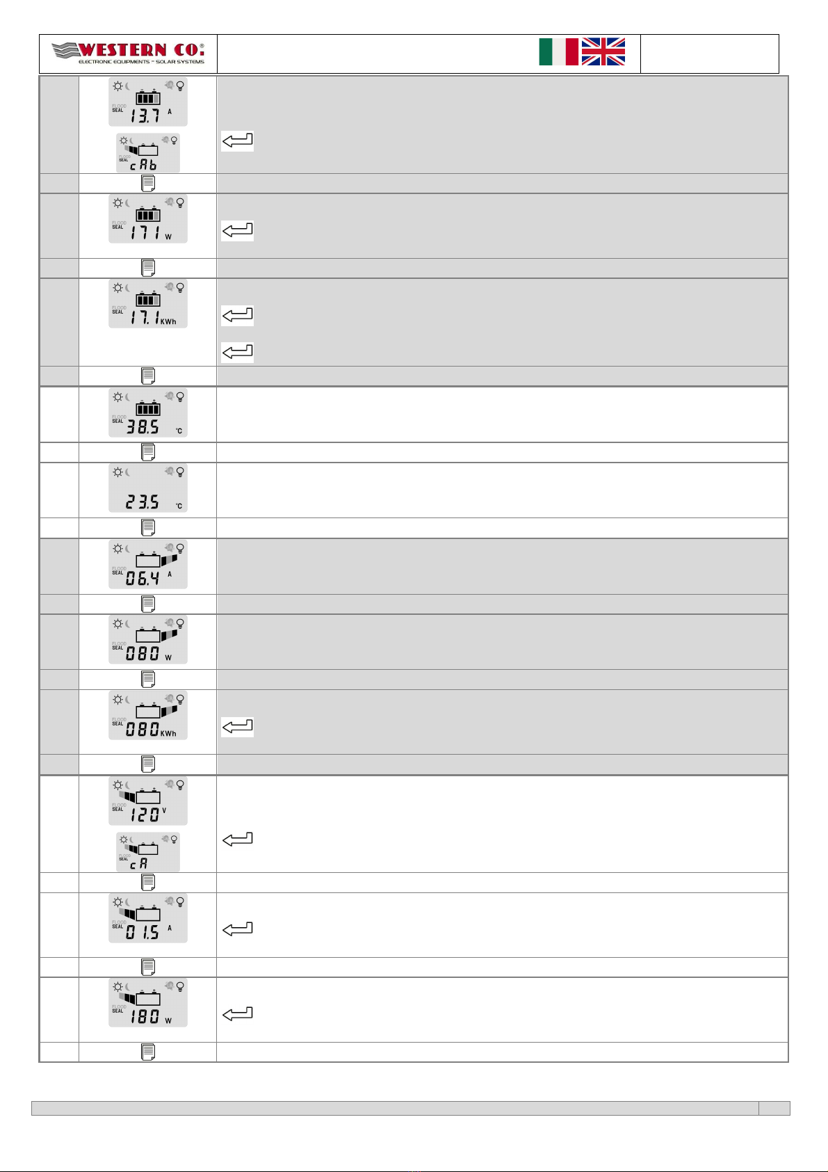
Carico sempre acceso sia di giorno che di notte.
(24h/24h)
. . .
Carico acceso solo di notte per le ore visualizzate. (Crepuscolare con timer)
Carico acceso solo di notte. (Crepuscolare completo)
Cari
co acceso solo di giorno. (Crepuscolare invertito)
6
Impost l sogli di tensione l di sotto dell qu le viene rilev t l notte.
Premendo questo tasto può essere modificata l’impostazione.
Mantenendo premuto per 1 sec. questo tasto si seleziona il valore di default.
I valori selezionabili sono: @12 ,@24 ,@48 : 2,00 ; 3,28 ; 4,56 ; 5,84 ;
7
Impost l mod lità utilizz t per l ricerc dell’MPPT.
Premendo questo tasto può essere modificata l’impostazione.
Mantenendo premuto per 1 sec. questo tasto si seleziona il valore di default.
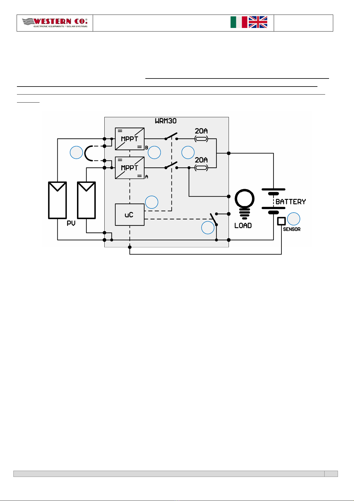
La selezione della modalità per la ricerca dell’MPPT è scelta tra le due seguenti in maniera automatica. (default)
I due canali A e B dei moduli fotovoltaici vengono considerati come parallelati, av
enti quindi un punto di massima potenza
comune.
I due canali A e B dei moduli fotovoltaici vengono considerati come indipendenti, cioè ognuno avente un proprio punto di
massima potenza.
8
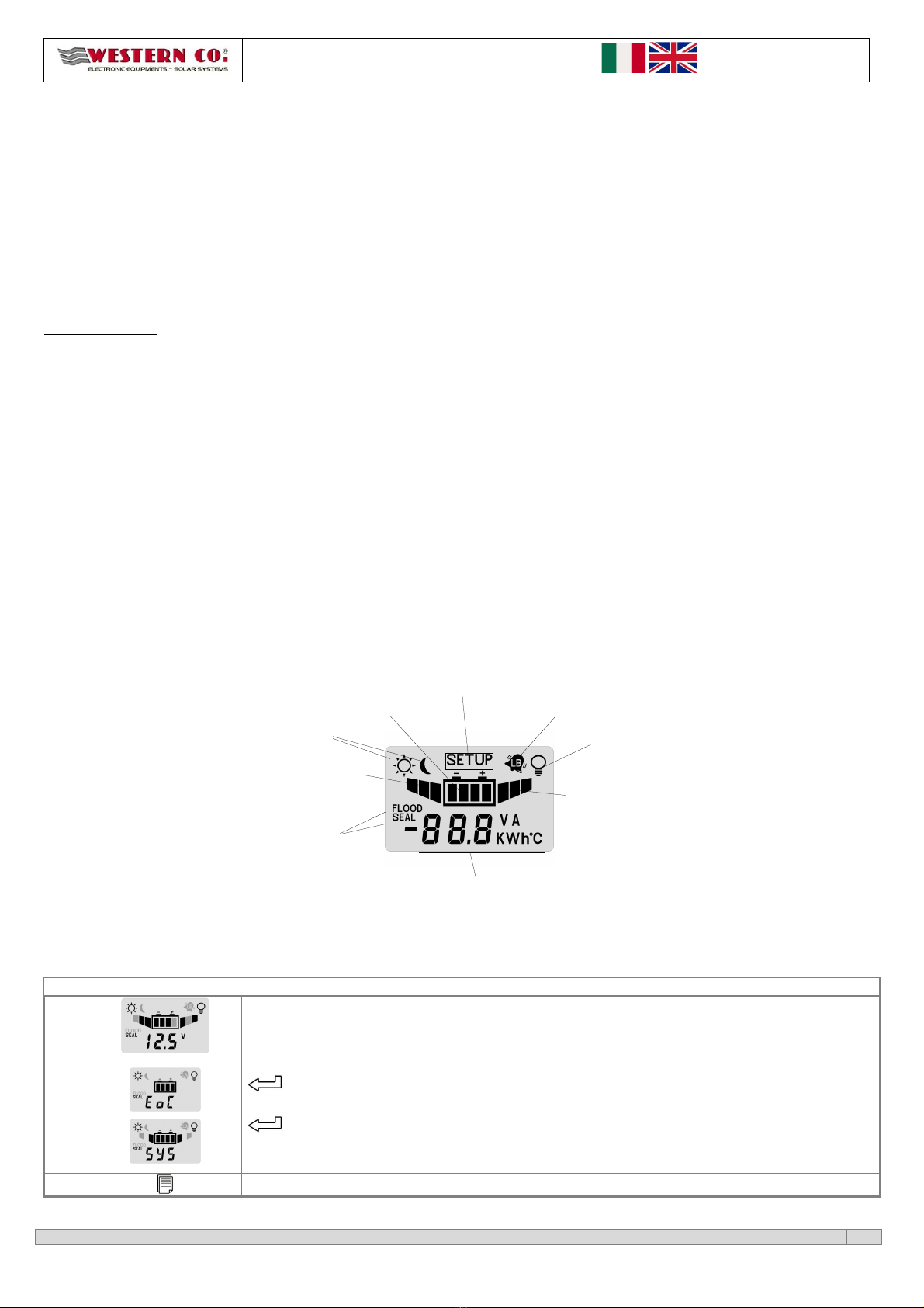
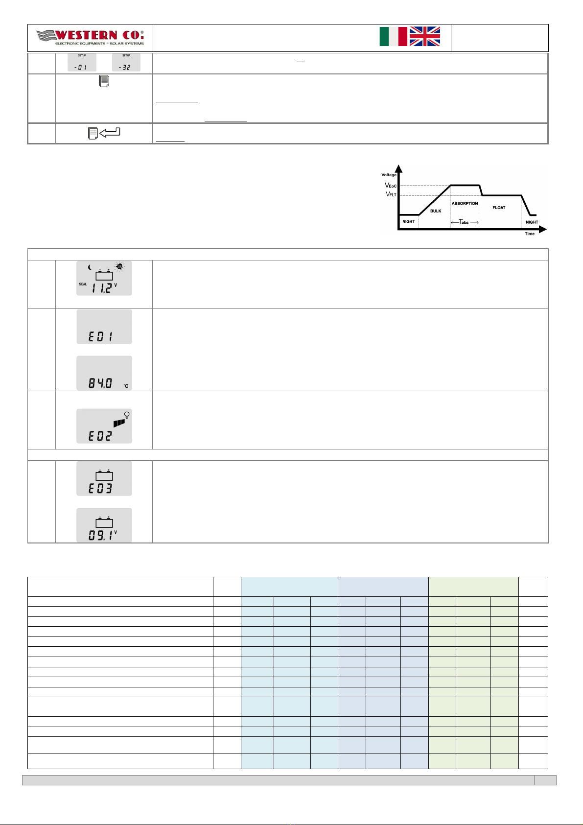
Imposta il tempo di absorption
2
.
Tempo in ore in cui la
batteria deve rimanere alla tensione EoC prima di passare alla
tensione EoC float.
Premendo questo tasto può essere modificata l’impostazione.
Mantenendo premuto per 1 sec. questo tasto si seleziona il valore di default.
. . .
I valori seleziona
bili sono da 1 a 8 ore. (default
4
ore
)
9
Imposta l’indirizzo di nodo MODBUS
3
.
Indirizzo che identifica il nodo in una rete con protocollo MODBUS su bus RS485.
Premendo questo tasto può essere modificata l’impostazione.
Mantenendo premuto per 1 sec. questo tasto si seleziona il valore di default.

WRM30 Manuale installazione
Rev.
1.3
11-11-2014
This document is the property of WESTERN CO. Srl - All rights are reserved - Reproduction and use of information contained within this document is forbidden without the written consent of WESTERN CO. Srl
9
. . .
I valori selezionabili sono da 1 a 32. (default
16
)
Da questa pagina, premendo questo tasto si ritorna alla 1^ pagina di configurazione.
Mantenendo premuti per 1 sec. questo tasto da qualsiasi pagina di configurazione si torna alle pagine di visualizzazione
senza salvare i parametri di configurazione modificati.
Se nessun tasto viene premuto per 2 minuti, da qualsiasi pagina di configurazione in automatico si torna alle pagine di
visualizzazione senza salvare i parametri di configurazione modificati.
Mantenendo premuti per 1 sec. questi tasti da qualsiasi pagina di configurazione si torna alle pagine di visualizzazione
salvando i parametri di configurazione modificati, i quali diventano operativi.
1
Contatore accessibile solo da remoto (MODBUS).
2
Grafico fasi di ricarica:
3
Per i comandi relativi al protocollo MODBUS fare riferimento al manuale di programmazione.
All rmi e errori del sistem
ALLARMI
1
Allar
me Low
-
battery
Il simbolo low battery lampeggiante indica che è intervenuta la protezione di batteria scarica e quindi per preservare la
vita della batteria è stato disconnesso il carico. Questa protezione interviene quando la tensione di batteria scende sotto
la soglia
LB
impostabile dall’utente. Il WRM30 esce da questa protezione quando la batteria sarà ricaricata dal modulo P
alla tensione
OUT
-
LB
.
2
…
Allarme sovratemperatura.
Interviene quando la temperatura interna del WRM30 supera i 65°C, disattiva la ricarica e disconnette il carico. Si esce
automaticamente da questa protezione quando la temperatura interna scende al di sotto della soglia di 50°C. La
temperatura interna rilevata è visualizzata sul display alternativamente all’errore 01.
3
…
Allarme sovraccarico.
Interviene quando la corrente del carico supera il limite massimo consentito per il WRM30 il regolatore disconnette il
carico per prevenire rotture interne. Nel caso intervenga questa segnalazione è necessario verificare se la corrente
assorbita dal carico è inferiore al limite consentito. Dopo 1 minuto il WRM30 tenta di alimentare nuovamente il carico e
esce da questo stato se è sta eliminata la causa che ha generato il sovraccarico. Dopo 3 eventi di sovraccarico occorre
attendere un evento notte per l’uscita dalla protezione.
CODICI D’ERRORE
4
…
Errore
tensione di batteria anomala.
All’avvio il regolatore ha rilevato una tensione di batteria anomala e quindi non è stato in grado di rilevare la tensione
nominale del sistema. Questo errore potrebbe essere causato da batterie eccessivamente scariche, quindi in caso di
comparsa di questo errore è necessario sostituire le batterie. La tensione anomala rilevata è visualizzata sul display
alternativamente all’errore 03. Per uscire da questo errore è necessario riavviare il sistema.
CARATTERISTICHE ELETTRICHE
Tensione nominale batteria
12V
Tensione nominale
batteria 24V
Tensione nominale
batteria 48V
UM
Min.
Tip.
Max.
Min.
Tip.
Max.
Min.
Tip.
Max.
Tensione di batteria
V
b t
t
10,0
12,
0
16,0
20,0
24,0
32,0
40,0
48,0
64,0
( )
Tensione di pannello a circuito aperto
V
p n
-
-
150
-
-
150
-
-
150
( )
Corrente di pannello
per canale
I
p n
-
-
1
3
-
-
13
-
-
1
3
(A)
Massima potenza di pannello
per canale
P
chM x
-
-
250
-
-
500
-
-
90
0
(W)
Tensione uscita carico
V
LOAD
-
Vb tt
-
-
Vb tt
-
-
Vb tt
-
( )
Corrente del carico
I
LOAD
-
-
1
5
-
-
15
-
-
15
(A)
Tensione di
ricarica a 25°C programma SEAL
V
EoC
-
14
,
4
-
-
28
,
8
-
-
57
,
6
-
( )
Tensione di ricarica a 25°C programma FLOOD
V
EoC
-
14
,
8
-
-
29
,
6
-
-
59
,
2
-
( )
Tensione di ricarica programma
Li
1
V
EoC
14,0
14,7
28,0
29,4
56,0
58,8
( )
Compensazione della
EoC
in
funzione della
temperatura di batteria (Tbatt)
1
V
t dj
- -0,024
- - -0,048
- - -0,096
- ( /°C)
Tensione della fase Float
a 25°C
V
flt
-
EoC-0,6
-
-
EoC-1,2
-
-
EoC-2,4
-
( )
Tempo fase Absorption (Impostabile)
T
bs
1
4
8
1
4
8
1
4
8
(h)
Tensione di low battery (impostabile)
V
lb
10,80
11
,
60
(default)
12,56 21,60 23,20 25,12 43,20
4
6
,
40
(default)
50,24 ( )
Tensione uscita
low battery a 25°C
V
elb
12,72
EoC-0,2
(default)
13,68 25,44
EoC-0,4
(default)
27,36 50,88
EoC-0,2
(default)
54,72 ( )

WRM30 Manuale installazione
Rev.
1.3
11-11-2014
This document is the property of WESTERN CO. Srl - All rights are reserved - Reproduction and use of information contained within this document is forbidden without the written consent of WESTERN CO. Srl
10
Tensione rilevazione notte: (impostabile)
V
night
2,00
4,56
(default)
5,84 2,00
4,56
(default)
5,84 2,00
4,56
(default)
5,84 ( )
Ten
sione rilevazione giorno
V
d y
-
8,40
-
-
8,40
-
-
8,40
-
( )
Auto consumo
I
q
-
34
-
-
21
-
-
12
-
(mA)
Temperatura di esercizio
T
mb
-10 - +40 -10 - +40 -10 - 40 (°C)
Potenza dissipata
P
loss
-
-
40
-
-
56
-
-
66
(W)
Rendimento @30A
n
90
-
92
93,5
-
95,
2
96,0
-
97,2
(%)
Sezione ai morsetti Batteria
35
(mm
2
)
Sezione ai morsetti
modulo P
10
(mm
2
)
Sezione ai morsetti
carico
4
(mm
2
)
Peso
2000
(g)
Grado di protezione
IP20
1
Con programma Li la tensione di fine carica non varia al variare della temperatura misurata
Tab. caratteristiche elettriche
Gr fici
Graf. 1 Andamento Tensione di fine carica in funzione della temperatura di batteria
Graf. 2 Efficienze

WRM30 Manuale installazione
Rev.
1.3
11-11-2014
This document is the property of WESTERN CO. Srl - All rights are reserved - Reproduction and use of information contained within this document is forbidden without the written consent of WESTERN CO. Srl
11
Dimensioni
Fig. Dimensioni (mm)
viti per apertura
sportello morsetti
elettrici

WRM30 Manuale installazione
Rev.
1.3
11-11-2014
This document is the property of WESTERN CO. Srl - All rights are reserved - Reproduction and use of information contained within this document is forbidden without the written consent of WESTERN CO. Srl
12
G r nzi di legge
Western Co srl garantisce la buona qualità e la buona costruzione dei Prodotti obbligandosi, durante il periodo di
garanzia di 5 (cinque) anni, a riparare o sostituire a sua sola discrezione, gratuitamente, quelle parti che, per cattiva
qualità del materiale o per difetto di lavorazione si dimostrassero difettose.
Il prodotto difettoso dovrà essere rispedito alla Western Co srl o a società delegata dalla Western Co srl a fare assistenza
sul prodotto, a spese del cliente, assieme ad una copia della fattura di vendita, sia per la riparazione che la sostituzione
garantita. I costi di re-installazione del materiale saranno a carico del cliente.
La Western Co srl sosterrà le spese di re spedizione del prodotto riparato o sostituito.
L g r nzi non copre i Prodotti che, in b se nostr discrezione, risultino difettosi c us di n tur le logor mento,
che presentino gu sti c us ti d imperizi o negligenz del cliente, d imperfett inst ll zione, d m nomissioni o
interventi diversi d lle istruzioni d noi fornite .
L g r nzi dec de ltresì in c so di d nni deriv nti d :
-trasporto e/o cattiva conservazione del prodotto.
-causa di forza maggiore o eventi catastrofici (gelo per temperature inferiori a -20°C, incendio, inondazioni, fulmini, atti
vandalici, ecc…).
Tutte le sopraccitate garanzie sono il solo ed esclusivo accordo che soprassiede ogni altra proposta o accordo verbale o
scritto e ogni ltr comunic zione f tt tr il produttore e l’ cquirente in rispetto qu nto sopr .
Per qualsiasi controversia il Foro competente è Ascoli Piceno.
Sm ltimento dei rifiuti
La Western Co in qualità di produttore del dispositivo elettrico descritto nel presente
manuale, ed in conformità al D.L 25/07/05 n 151, informa l’acquirente che questo
prodotto, una volta dismesso, deve essere consegnato ad un centro di raccolta
autorizzato oppure, in caso di acquisto di apparecchiatura equivalente può essere
riconsegnato a titolo gratuito al distributore della apparecchiatura nuova.
Le sanzioni per chi abusivamente si libera di un rifiuto elettronico saranno applicate
dalle singole amministrazioni comunali.
WESTERN CO. srl
ia Pasubio 1
63037 San Benedetto del Tronto (AP)
tel 0735 751248 fax 0735 751254
e-mail: [email protected]
web: www.western.it

WRM30 – User Manual
Rev.
1.2
18-03-2014
This document is the property of WESTERN CO. Srl - All rights are reserved - Reproduction and use of information contained within this document is forbidden without the written consent of WESTERN CO. Srl
13
PV CHARGE CONTROLLER
WRM30
WRM30 is a P charge controller for big off-grid systems. It is suitable for
12 /24 /48 systems and it can handle a photovoltaic power up to 1.5/1.8kW.
WRM30 has been properly designed for industrial applications such as the
power supplying of either T /radio bridges, road signs, or whole houses
completely off-grid.
WRM30 implements a research circuit for the maximum power of panel
(MPPT): regardless of battery voltage and its state of charge, the charge
controller makes always the P module work at its point of maximum power
maximizing the energy extracted from the P module and charged into the
battery. Charging is temperature-compensated.
Special feature of this product is the presence of two separated charging
channels and, therefore, a double input for P modules. This allows the
management of two independent strings, for example in the case they are
composed of modules with different features or exposed on two slopes, or,
with identical strings, channels can be paralleled thus optimizing efficiency.
The load output can be activated according to several programs that can be
selected by the user: load ON 24h/24h, load ON only during the day, load ON
only during night and load ON during night for a number of hours from 1 to 16.
WRM30 detects the day/night status according to the P module’s voltage; so
it is not necessary to connect additional sensors to the controller.
It is equipped with a RS485 serial interface through which you can access all of
the available functionalities.
Features:
•12V / 24V and 48V battery voltage
•12V / 24V / 48V auto detect.
•MPPT charge
•Max charge current: 3 A
•For sealed/GEL, flooded lead acid
batteries and lithium-ion batteries
(from rev 1.1)
•Charge voltage compensated in
temperature
•Integrated blocking diode
•Max power of PV modules: 45 W@12V
/ 9 W@24V / 18 W@48V.
•Max Voc voltage on PV modules: 15 V.
•Double input of PV modules.
•Configurable parameters by two
buttons and LCD
•18 load management programs
•Maximum load current: 15A.
•Low battery protection
•Over temperature protection.
•Battery reverse polarity protection.
•Overload protection on output.
•RS485 interface.
•IP2 metal box
•Terminals for battery cables 35sqmm
•Terminals for PV modules cables
1 sqmm
•Terminals for load cables 4sqmm

WRM30 – User Manual
Rev.
1.2
18-03-2014
This document is the property of WESTERN CO. Srl - All rights are reserved - Reproduction and use of information contained within this document is forbidden without the written consent of WESTERN CO. Srl
14
Gener l description
WRM30 is a P charge controller for either sealed (SEAL) or flooded lead acid (FLOOD) electrochemical lead batteries.
From firmware version 1.1 onwards we introduced the charge program for lithium-ion batteries (Li-Ion) with integrated
Battery Management System (BMS); I advise you to contact Western Co. to select the right lithium-ion battery to
connect to WRM30 charge controller. It is absolutely forbidden to connect to WRM30 lithium-ion batteries without
BMS; the BMS protects the battery from unsafe operating conditions that can lead to battery’s explosion or burning.
In fig. 1 there is a principle diagram of WRM30.
Fig. 1 Principle diagram
1- Charging circuit: it consists of two identical but distinct channels. It adapts PAN and IPAN (respectively voltage and
current of the P module) in order to search for the condition in which the power delivered by the P module is
maximum, realizing what in the technical literature is indicated with the acronym MPPT (Maximum Power Point
Tracking). It also manages the battery charging reducing the current delivered to the battery in the conditions in
which the voltage
batt
equals its charging voltage
EoC.
2- Parallel/Independent: this external connection
1
must be inserted when you have either a single photovoltaic field or
a separated one but on a single flap. With the external jumper the charge controller sees a single photovoltaic field
and distributes power equally between the channels. In a system with two slopes or in any case where you want to
maintain the channels independent, the jumper must not be inserted and the charge controller will search for two
different MPPT
2
.
3- Protections: The switches act as an anti-reverse battery protection and blocking diode. They avoid that during the
night, when the P module is not illuminated, it can absorb current from the battery. Internal fuses provide an
additional degree of protection.
4- Load: the load
3
is power supplied with the same battery voltage and it is controlled through a semiconductor switch.
5- Microprocessor: it controls the whole circuit; it measures currents and voltages of P modules, battery and load, and
it shows them on the display.
6- For a more precise detection of battery voltage and temperature, WRM30 uses a sensor to be positioned close to the
terminals of battery (the sensor is supplied: SPC20.S). It is important to connect this sensor to guarantee the
compensation in temperature of the end-charge voltage of the system (
EoC
) and for a measure of battery voltage
independent of the voltage drop on cables. If you do not connect this sensor the system will work equally but the
battery voltage will be measured on the internal terminals of WRM30, while the compensation
EoC
in function of the
temperature will not be performed and, prudentially, the
EoC
will be set to the minimum value, as if the system
detects a temperature 60°C.
1
2
5
4
3
6

WRM30 – User Manual
Rev.
1.2
18-03-2014
This document is the property of WESTERN CO. Srl - All rights are reserved - Reproduction and use of information contained within this document is forbidden without the written consent of WESTERN CO. Srl
15
WRM30 has got an automatic detection of battery voltage which is executed at power on; consequently it sets the
proper charging parameters as described in table 1.
B ttery volt ge me sured t st rtup Detected nomin l volt ge
10.0 <
batt
< 16.0
Battery at 12
20.0 <
batt
< 32.0
Battery at 24
40.0 <
batt
< 64.0
Battery at 48
Tab. 1 Recognition thresholds of battery nominal voltage
If the battery voltage does not fall in one of the bands on table 1 , WRM30 will report the error E03 (see§
Al rms nd
errors of the system
); charging and load will be deactivated. If this error appears check for proper voltage of the battery
bank, then re-execute the start-up.
1
The jumper is made with a conductor having a section of at least 2.5 mm2.
2
Never exceed the PchMax for each channel.
3
The load has got the positive terminal in common with the positive of battery, while the “minus” is switched through the internal switch (never connect the minus
of the load with the minus of the battery!)
Choice of PV module
Thanks to its charging circuit with MPPT, WRM30 charge controller allows the use of a wide range of P modules
ensuring the optimal exploitation of the whole power. The P module must be selected according to the nominal
battery voltage and respecting the constraints of the panel input of WRM30. The below reported table 2 gives an
indication of the recommended ranges that are accepted in input on each P channel of the charge controller.
Nominal battery voltage
Features of PV strings
@25°C
(per channel) Range
12V
mp
: voltage at maximum power
OC
: open circuit voltage
P
MAX
: max power
N
cs
: number of cells in series
1
15,0
≤
mp
≤
30
<40
< 225W
36≤ N
cs
≤60
24V
mp
: voltage at maximum power
OC
: open circuit voltage
P
MAX
: max power
N
cs
: number of cells in series
1
30,0
≤
mp
≤
60
<80
< 450W
72≤ N
cs
≤112
48V
mp
: voltage at maximum power
OC
: open circuit voltage
P
MAX
: max power
N
cs
: number of cells in series
1
60,0
≤
mp
≤
120
<140
< 900W
144≤ N
cs
≤168
Table 2 Selection of PV strings
1
alues refer to mono or poly crystalline silicon P modules.
Installation
1) Install WRM30 in a dry and adequately ventilated place, fixed on a non-flammable surface and positioned so as to
leave an unobstructed space of at least 10cm in the neighbourhood of device that allows the cooling for natural air
convection or forced by the internal fan.
2) Remove the front cover to access to electrical connections (see fig. ).
3) Connect in order: load, sensor for measure of battery temperature and voltage (included), P module, and finally
the battery as in the diagram fig. 2. At battery connection, the charge controller turns on and starts to work. The
cable sections must be chosen so that in each length of cable the maximum permissible voltage drop is less than 3%
of the system nominal voltage (Table 3).
4) You can connect to WRM30 lead batteries with 12 , 24 or 48 nominal voltage. At power on the charge controller
measures the battery voltage, it recognizes the nominal voltage of the battery bank connected to it and it
automatically sets the correct levels of charging voltage (see §
Gener l description
). The user must, however,
configure the type of battery being used to adjust the correct charging voltage (
EoC
). Please set SEAL configuration if
you use either RLA sealed or GEL batteries, while set FLOOD configuration if you use flooded lead acid batteries
(see §
System configur tion
).

WRM30 – User Manual
Rev.
1.2
18-03-2014
This document is the property of WESTERN CO. Srl - All rights are reserved - Reproduction and use of information contained within this document is forbidden without the written consent of WESTERN CO. Srl
16
5) Set the load management program proper for your own application. Note: do not connect to the LOAD output loads
that absorb a current > 15A, otherwise the system goes into over current protection (
E02
) and the load is not power
supplied.
6) Mount the supplied cable-clamps so that the weight of the cables is not discharged on the electrical terminals, but on
the same cable-clamp and install the front cover to protect the electrical connections.
1
For the cables of load and battery temperature there are not specific cable glands, they must be anchored with cable ties on those of battery.
Wiring di gr m
Recommended section pairs of copper
cable
that guarantee a
maximum voltage drop of 3% of the battery nominal voltage
Max distance per
couple [m]
@ 12V
C ble section
6
mm
2
10
mm
2
16
mm
2
25
mm
2
32 mm
2
Current
10A 6,3 10,5 16,7 26,2 33,5
20A 3,1 5,2 8,4 13,1 16,7
30A 2,1 3,5 5,6 8,7 11,2
Max distance per
couple [m]
@ 24V
C ble section
6
mm
2
10
mm
2
16
mm
2
25
mm
2
32 mm
2
Current
10A 6,3 10,5 16,7 26,2 33,5
20A 3,1 5,2 8,4 13,1 16,7
30A 2,1 3,5 5,6 8,7 11,2
Max distance per
couple [m]
@ 48V
C ble section
6
mm
2
10
mm
2
16
mm
2
25
mm
2
32 mm
2
Current
10° 6,3 10,5 16,7 26,2 33,5
20A 3,1 5,2 8,4 13,1 16,7
30A 2,1 3,5 5,6 8,7 11,2
Table 3 Choice of cables’ section
Fig. 2 Wiring diagram
System testing
Once made the connections as shown in Fig. 3 it is necessary to test the system.
1) At power on, the display will temporarily indicate the firmware revision (see § System configuration - point 1) and
soon after it will show a screen with the detected nominal voltage of the system (see §
Views
point 1-b).
2) Make sure that the read voltage corresponds to that of the system. The displaying of the system nominal voltage
can be repeated (see §
Views
point 1-b).
ref
. page 2
point
(2)

WRM30 – User Manual
Rev.
1.2
18-03-2014
This document is the property of WESTERN CO. Srl - All rights are reserved - Reproduction and use of information contained within this document is forbidden without the written consent of WESTERN CO. Srl
17
3) erify that in the main page or in the one dedicated to the reading of battery temperature (see §
Views
point 5),
the battery icon and the ‘°C’ symbol are not flashing; this to indicate the correct connection of the voltage probe
and the battery temperature.
4) With the P module exposed to sunlight, check that WRM30 charges the battery going to read the charging current
I
chA
+ I
chB
(see §
Views
point2).
5) Check the proper power ON of the load. If the load is ON only during night you can simulate the night by
disconnecting temporarily one of the wires of the P module. Otherwise you can set temporarily the load
programming at 24h/24h, (see §
System configur tion
point 5).
6) With the load ON, check the current absorbed by it reading the parameter I
LOAD
in the proper page of LCD (see §
iews point 7).
WARNING:
To turn off the system please follow these steps:
1)
Disconnect PV modules
2)
Wait (~3 sec.) until in the display disappears the animation inside the battery icon (fig. 3 - charging current
indicator )
3)
Disconnect battery
If not complied these recommended steps, the WRM3 can be damaged.
Views
WRM30 is equipped with a display and two buttons for the user interface. It is organized in two environments: one for
displaying and one to configure. In the first one there is a main screen which summarizes the most important
information of the system; then other main screens show in detail other values. The other environment concerns the
configuration where the operating parameters of the system are set. The various sequences are detailed in the
following tables, on those of displaying some are grouped (different frame and background) as they are logically linked
by a common reference: values referred to both channels, temperature, load, channel A and channel B.
Day / night
sta tus
o n config uration
Low battery p rotectio n
Lo ad status
Charg e program
Vi ewer o f internal
measure s
Load
cu rrent indicat or
PV module cu rrent i ndicat or
Ch arging cur rent
indicator
Fig. 3 Display
PAGES SEQUENCE OF STATUS VISUALIZATION AND PARAMETERS
1
1-a
1-b
M in p ge.
It displays the battery voltage (
BAT
), the charging program currently selected (SEAL or FLOOD), the day/night status
detected by the P module; The load status icon, if ON, indicates that the load is power supplied. Finally, there is the low
battery alarm. The animation
1
of the bars indicates presence of current respectively: from P module, while charging, and
towards the load.
By pressing this button it appears temporarily the current end-charge voltage (it is function of detected battery
temperature), evidenced by “EoC” c
Pressing and holding for 1 sec. this button it occurs temporarily the system nominal voltage (12 / 24 / 48 ),
evidenced by “SYS” and then the value in olts. Here you can also see the indication concerning the use of local battery
voltage (two bars near the battery symbol) or remote (two bars far from the battery symbol).
2
It displ ys the tot l ch rging current of both ch nnels (I
chA+
I
chB
).
Other indic
ations remain the same of the main page
with
only the animation of the current in charge.

WRM30 – User Manual
Rev.
1.2
18-03-2014
This document is the property of WESTERN CO. Srl - All rights are reserved - Reproduction and use of information contained within this document is forbidden without the written consent of WESTERN CO. Srl
18
2-a
By pressing this button it appears temporarily the reference to the displayed channels: in this case “cAb”, that is the
value, is related to both channels A+B.
3
It displ ys the tot l ch rge current of both ch nnels (P
chA+
P
chB
).
The other indications of the main page remain with only the
animation of the charging current.
Pressing this button it appears temporarily the reference to the displayed channels: in this case “cAb”, that is the
value, is relative to both channels A + B.
4
It displ ys the counter of tot l ch rge energy of both ch nnels (E
chA+EchB
).
The other indications of the main page remain
with only the animation of the charging current.
Pressing this button it appears temporarily the reference to the displayed channels: in this case “cAb”, that is the
value, is relative to both channels A + B.
Pressing this button for 1 sec. this energy counter is reset to zero
5
It displ ys the b ttery temper ture detected by the extern l sensor (T
BAT
).
The other indications of the main page remain,
except for animations. A flash of the battery icon and of “°C” symbol indicates the absence of remote temperature sensor².
6
It displ ys the temper ture detected by the sensor th t is inside WRM30 (T
INT
).
You can see the indications of the
following icons: day/night, load status and low battery alarm.
7
It displ ys the current bsorbed by the lo d (I
LOAD
).
The ot
her indications of the main page remain with only the animation
of the load current.
8
It displ ys the power bsorbed by the lo d (P
LOAD
).
The other indications of the main page remain with only the animation
of the load current.
9
It displ ys the counter of energy bsorbed by the lo d (E
LOAD
).
The other indications of the main page remain with only the
animation of the load current.
Pressing this button for 1 sec. this energy counter is reset to zero.
10
10-a
It
displ ys the volt ge on the module of ch nnel A (V
chA
).
The other indications of the main page remain with only the
animation of the P module current.
Pressing this button it appears temporarily the reference to the displayed channel: in this case “cA”, that is the
value, is relative to channel A.
11
It displ ys the current
³
delivered by the single module of ch nnel A (I
chA
).
The other indications of the main page remain
except the animation of the P module current.
Pressing this button it appears temporarily the reference to the displayed channel: in this case “cA”, that is the
value, is relative to channel A.
12
It displ ys the power
³
of the module of ch nnel A (P
chA
). The other indications of the main page remain with only the animation of the P module
current.
Pressing this button it appears temporarily the reference to the displayed channel: in this case “cA”, that is the
value, is relative to channel A.
13
It displ ys the counter of energy supplied by the mod
ule of ch nnel A (E
chA
).
The other indications of the main page remain
with only the animation of the P module current.

WRM30 – User Manual
Rev.
1.2
18-03-2014
This document is the property of WESTERN CO. Srl - All rights are reserved - Reproduction and use of information contained within this document is forbidden without the written consent of WESTERN CO. Srl
19
Pressing this button it appears temporarily the reference to the displayed channel: in this case “cA”, that is the
value, is relative to channel A.
Pressing this button for 1 sec. this energy counter is reset to zero.
14
14-a
It displ ys the volt ge
on
the module of ch nnel B (V
chB
).
The other indications of the main page remain except the
animation of the P module current.
Pressing this button it appears temporarily the reference to the displayed channel: in this case “c b”, that is the
value, is relative to channel B.
15
It displ ys the current
3
delivered by the single module of ch nnel B (I
chB
).
The o
ther indications of the main page remain
except the animation of the P module current.
Pressing this button it appears temporarily the reference to the displayed channel: in this case “c b”, that is the
value, is relative to channel B.
16
It
displ ys the power
3
of the module of ch nnel B (P
chB
).
The other indications of the main page remain except the
animation of the P module current.
Pressing this button it appears temporarily the reference to the displayed channel in this case “c b”, that is the
value, is relative to channel B.
17
It displ ys the counter of energy supplied by the module of ch nnel B (E
chB
).
The other indications of the main page remain
except the animation of the P module current.
Pressing this button it appears temporarily the reference to the displayed channel: in this case “c b”, that is the
value, is relative to channel B.
Pressing this button for 1 sec. this energy counter is reset to zero.
From this page, pressing this button, you return to the m
ain page.
- Pressing and holding for 1 sec. this button you go back to the main page from any other page.
- If you do not press any button for 2 minutes, you go back automatically to the main page from any other page. This is also
true in the environment of Configuration (see next paragraph).
1
Animations on the first page appear in the following cases: the animation “panel current” only if it is day, the animation “charging current” only if the charge is on,
the animation “Load current” only if the output is on.
2
This information is also shown on the first page but with a lower frequency of flashing.
3
The current and power of the module for each channel (I
chX
) are not directly measured but they are recalculated internally.
System configur tion
Point
SEQUENCE OF PAGES FOR SYSTEM CONFIGURATION
Pressing for 1 sec. these buttons from any display page you go to the configuration pages.
1
It displ ys the firmw re revision of the ch rge controller.
Pressing this button for 1 sec. all internal counters of: NCicli
1
, NLowBatt
1
, NOverLoad
1
, NOverTemp
1
, ContaOre
1
are set to zero (except energy counters).
2
It sets the ch rging volt ge for b ttery.
The displayed voltage refers to the end-charge voltage at 25°C.
Pressing this button you can modify the setting.
Pressing this button for 1 sec. you select the default value.
FLOOD program has to be set for the charge of flooded lead acid batteries.
SEAL program has to be set for either GEL or sealed batteries (default).
LEO program has to be set when you connect Western Co. Leonardo inverter to the battery.
. . .
Li program must be used for the charge of Li-Ion batteries setting the end-charge voltage according to the instructions of
the manufacturer of the lithium battery.
The selectable values (in steps of 0.1 ) are:
14,0 ; 14,1 ; 14,2 ; 14,3 ; 14,4 ; 14,5 ; 14,6 ; 14,7 ; for 12 systems
28,0 ; 28,2 ; 28,4 ; 28,6 ; 28,8 ; 29,0 ; ,29,2 ; 29,4 ; for 24 systems
56,0 ; 56,4 ; 56,8 ; 57,2 ; 57,6 ; 58,0 ; 58,4 ; 58,8 ; for 48 systems

WRM30 – User Manual
Rev.
1.2
18-03-2014
This document is the property of WESTERN CO. Srl - All rights are reserved - Reproduction and use of information contained within this document is forbidden without the written consent of WESTERN CO. Srl
20
To choos
e the correct value of charging voltage for
Li
-
Ion
batteries,
you need to consult the manual of your selected
battery.
When the Li program is active, the end-charge voltage is not temperature compensated and it is set to the selected value
for each temperature value read by WRM30.
3
It sets the volt ge threshold of intervention of Low
-
B ttery protection
(load disconnect
ion
in case of low battery).
Pressing this button you can modify the setting.
Pressing this button for 1 sec. you select the default value.
The selectable values are:
@12 : 10,80 ; 10,96 ; 11,12 ; 11,28 ; 11,44 ; 11,60 ; 11,76 ; 11,92 ; 12,08 ; 12,24 ; 12,40 ; 12,56 ;
@24 : 21,60 ; 21,92 ; 22,24 ; 22,56 ; 22,88 ; 23,20 ; 23,52 ; 23,84 ; 24,16 ; 24,48 ; 24,80 ; 25,12 ;
@48 : 43,20 ; 43,84 ; 44,48 ; 45,12 ; 45,76 ; 46,40 ; 47,04 ; 47,68 ; 48,32 ; 48,96 ; 49,60 ; 50,24 ;
4
It sets the threshold of the output volt ge from Low
-
B ttery protection
(back to normal functionality).
Pressing this button you can modify the setting.
Pressing this button for 1 sec. you select the default value.
The selectable values are:
@12 : Aut( EoC-0,20 ); 12,72 ; 12,88 ; 13,04 ; 13,20 ; 13,36 ; 13,52 ; 13,68 ;
@24 : Aut( EoC-0,40 ); 25,44 ; 25,76 ; 26,08 ; 26,40 ; 26,72 ; 27,04 ; 27,36
@48 : Aut( EoC-0,80 ); 50,88 ; 51,52 ; 52,16 ; 52,80 ; 53,44 ; 54,08 ; 54,72
5
It sets the mode of lo d oper tion.
Pressing this button you can modify the setting.
Pressing this button for 1 sec. you select the default value.
Load always ON during both day and night
(24h/24h).
. . .
Load ON only d
uring the night for the displayed hours (light sensor with timer).
Load ON only during night (complete light sensor).
Load ON only during day (inverted light sensor).
6
It sets the volt ge threshold below which the night is detected.
Pressing this button you can modify the setting.
Pressing this button for 1 sec. you select the default value.
The selectable values are: @12 ,@24 ,@48 : 2,00 ; 3,28 ; 4,56 ; 5,84 ;
7
It sets the mode used to se rch for MPPT.
Pressing this button you can modify the setting.
Pressing this button for 1 sec. you select the default value.
The mode selection for MPPT search is chosen between the following two in an automatic way (default).
The two channels A and B of P modules are considered
as paralleled, therefore having a common point of maximum
power.
The two channels A and B of P modules are considered as independent, that is, each with its own point of maximum
power.
8
It sets the time of absorption
2
.
Time in hours in which
the battery must remain at EoC
voltage
before going to
the
voltage: EoC float.
Pressing this button you can modify the setting.
Pressing this button for 1 sec. you select the default value.
. . .
The selectable values are from 1 to 8 hours (de
fault
4 hours
).
9
It sets MODB
US
3
node add
ress.
This address identifies
the net
node with MODBUS
protocol
on RS485 bus.
Pressing this button you can modify the setting.
Pressing this button for 1 sec. you select the default value.
. . .
The selectable values are from 1 to 32 hours (default
16 hours
).
From this page, if you press this button you go back to the 1^ page of configuration.
Table of contents
Languages:
Other Western Co Controllers manuals
Popular Controllers manuals by other brands

DoorBird
DoorBird A1081 Series installation manual

Omega
Omega HE-XL103 manual

YASKAWA
YASKAWA MP210 Series user manual

Curtiss-Wright
Curtiss-Wright EXLAR GTX Series Installation & service instructions

Distech Controls
Distech Controls DA-016N024PX installation instructions

Dantherm
Dantherm 970005 Service manual