Western Co WRM-20+ User manual

WRM-20 e WRM-20+ Manuale installazione
WRM-20 and WRM-20+ User Manual
ITA
ENG
Rev. 1.2
25-07-2017
This document is the property of WESTERN CO. Srl -All rights are reserved - Reproduction and use of information contained within this document is forbidden without the written consent of WESTERN CO. Srl
1
REGOLATORE DI CARICA BATTERIA
DA MODULO FOTOVOLTAICO
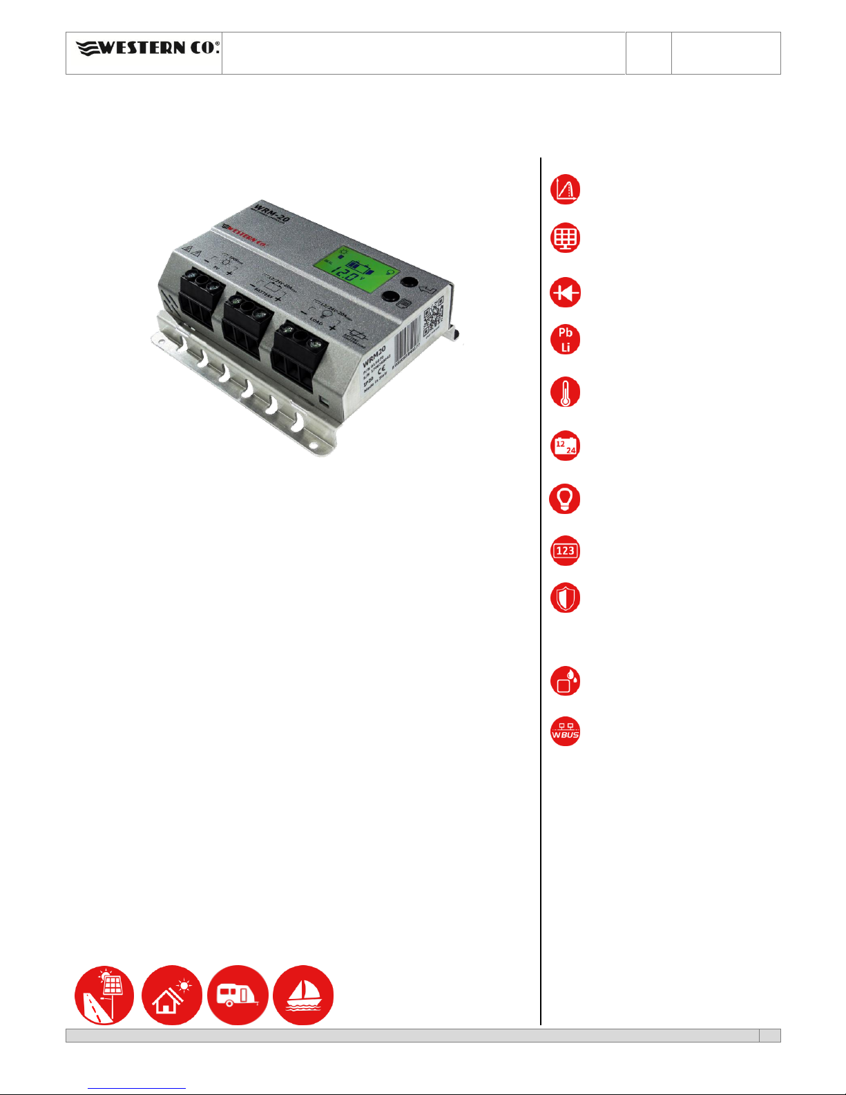
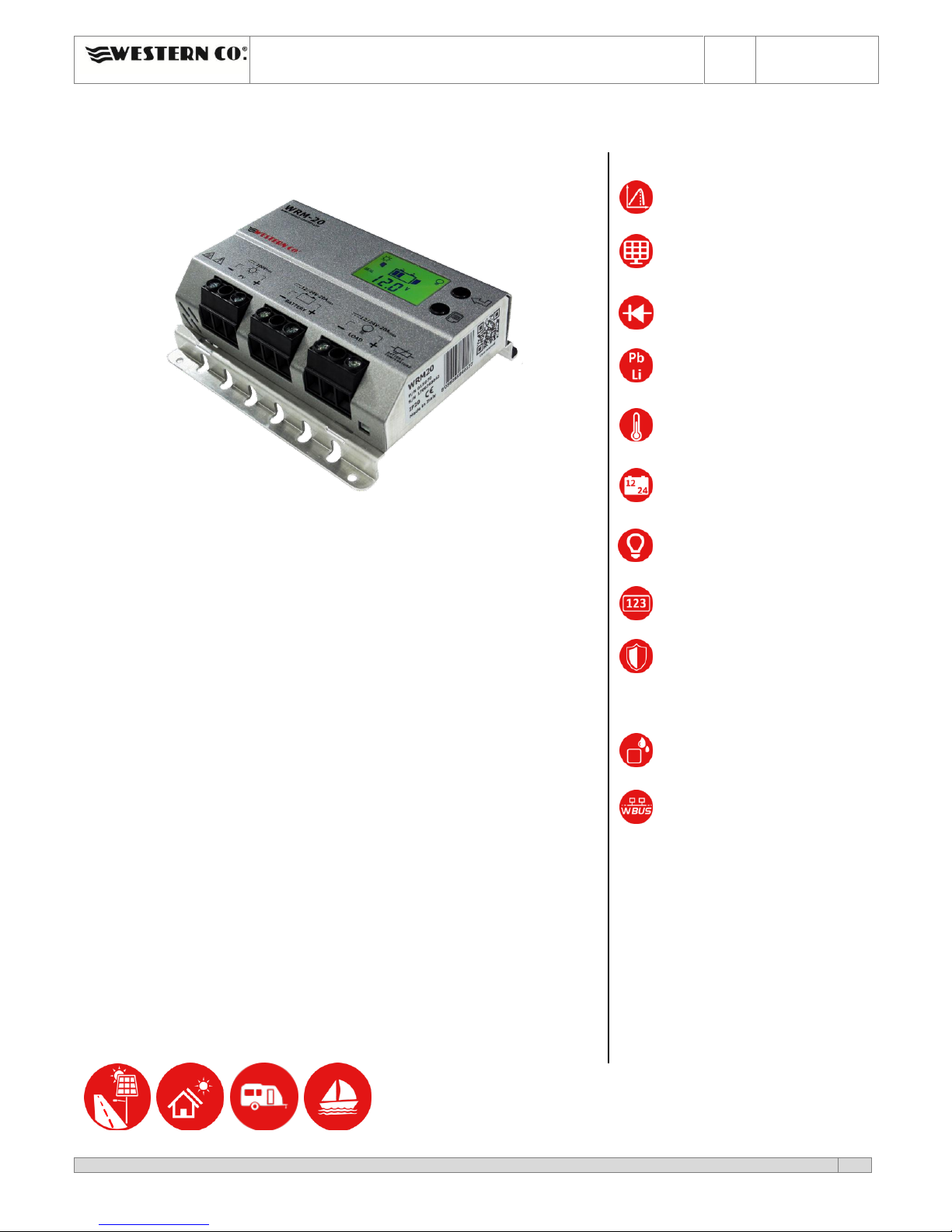
WRM-20
WRM-20+ con porta RS 485 protocollo WBus
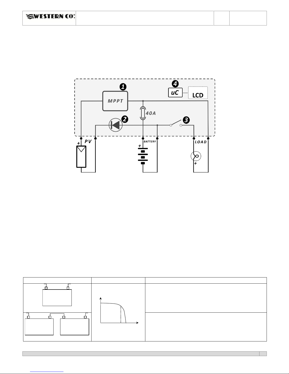
Il WRM-20 è una soluzione completa per la realizzazione di impianti
fotovoltaici ad isola, per alimentare sistemi di segnaletica stradale, sistemi di
illuminazione, piccole utenze a bassa tensione e per la ricarica di batterie
all’interno dei camper o imbarcazioni. Questo regolatore di carica implementa
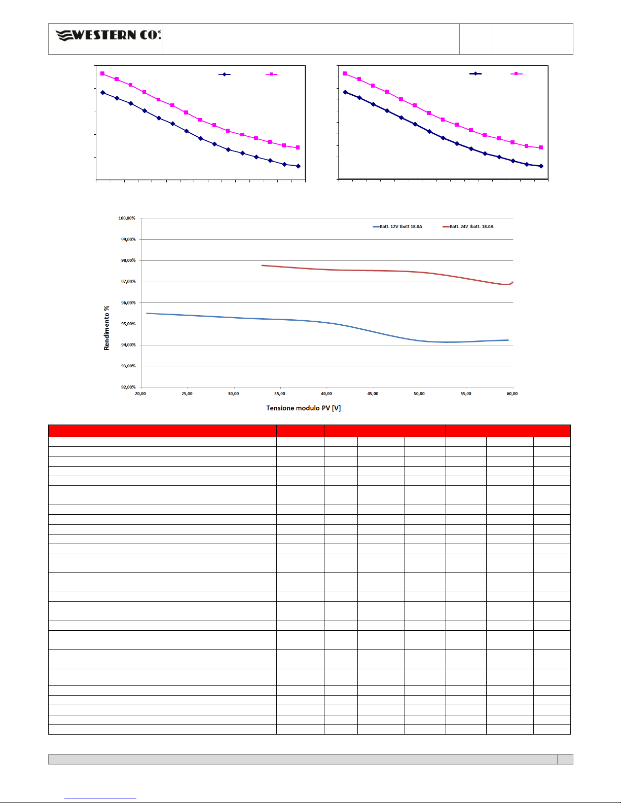
un circuito di ricerca della massima potenza di pannello (MPPT) che,
indipendentemente dalla tensione di batteria e dal suo stato di carica, fa
sempre lavorare il modulo PV nel suo punto di massima potenza
massimizzando l’energia caricata in batteria. A differenza dei regolatori di
carica di tipo PWM che richiedono l’impiego di moduli PV con N°36 celle per la
carica di batteria a 12V, e moduli a 72 celle per la ricarica di batterie a 24V con
il regolatore WRM20 questo vincolo di progetto non è più necessario, si
possono quindi installare, anche nei sistemi fotovoltaici a batteria, i più
economici moduli normalmente impiegati per sistemi connessi a rete con
numero di celle diverso da 36 o 72. Si possono inoltre impiegare i moduli in
silicio amorfo, normalmente non adatti ai regolatori PWM.
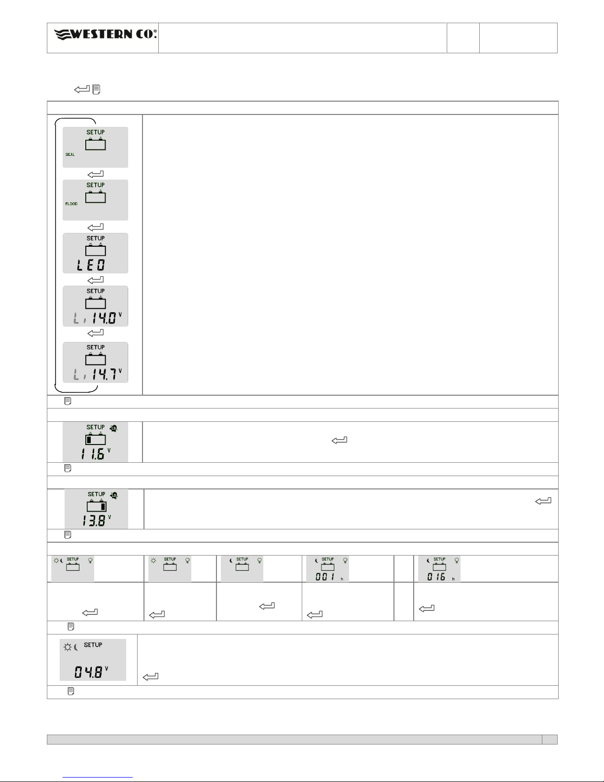
I vari programmi di gestione carico selezionabili dall’utente rendono il WRM-
20 la soluzione completa in molte applicazioni; ad esempio per alimentare
telecamere che debbono funzionare solo di giorno, oppure per alimentare
lampeggiatori o segnalazioni stradali che debbono funzionare solo di notte o
per alimentare sistemi di illuminazione che debbono funzionare per un
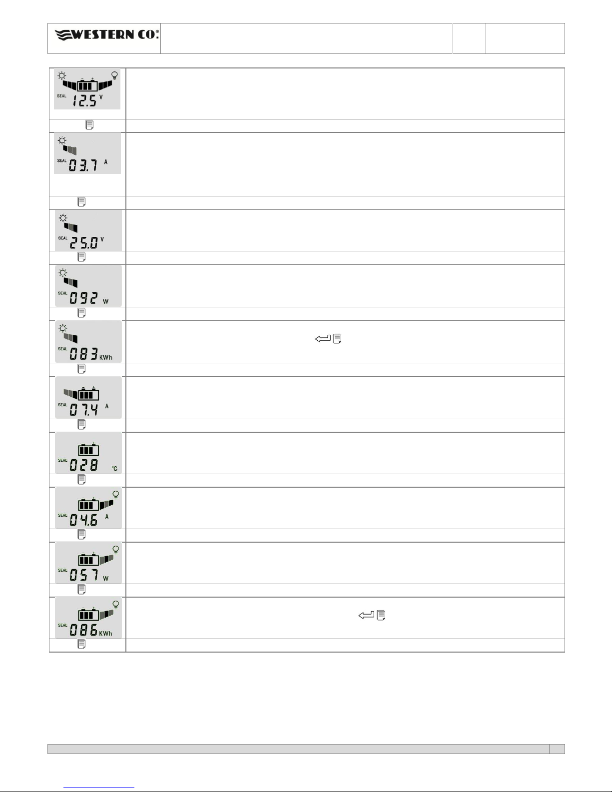
determinato numero di ore per notte. Un ampio display visualizza la tensione
di batteria, la corrente di carica dal modulo PV, quella del carco carico
collegato in uscita, e altre variabili.
Il modello WRM-20+ è fornito con una porta di comunicazione RS485 che
implementa il protocollo WBus e permette di collegare il display WRD della
Western CO per il datalogger e il controllo remoto. La Western CO fornisce il
protocollo di comunicazione su questa porta e quindi l’utente può
implementare un proprio dispositivo datalogger o controllo remoto.
Ricarica MPPT step down
Massima potenza di modulo fotovoltaico
310W per batteria a 12V
620W per batteria a 24V
Diodo di blocco integrato
Per batterie Pb ermetiche/GEL, acido libero
e batterie agli ioni di Litio
Tensione di ricarica compensata in
temperatura
Auto-detect tensione di batteria 12V / 24V
18 programmi per gestione carico
LCD per interfaccia utente
Protezioni:
Protezione batteria scarica
Protezione sovra-temperatura
Protezione inversione polarità batteria
Protezione sovraccarico su uscita
Contenitore in metallico IP20
Porta di comunicazione RS 485 con
protocollo WBus proprietario Western CO
per data-logger o controllo con display
remoto WRD. (solo per versione WRM-20+)

WRM-20 e WRM-20+ Manuale installazione
WRM-20 and WRM-20+ User Manual
ITA
ENG
Rev. 1.2
25-07-2017
This document is the property of WESTERN CO. Srl -All rights are reserved - Reproduction and use of information contained within this document is forbidden without the written consent of WESTERN CO. Srl
2
Descrizione generale
WRM-20 è un regolatore di carica da moduli fotovoltaici per batterie elettrochimiche al piombo di tipo ermetico (SEAL)
o ad acido libero (FLOOD) e di batterie agli ioni di litio del tipo che hanno integrato il BMS (Battery Management
System); consigliamo di contattare la Western CO per la scelta della batteria agli ioni di Litio da collegare al WRM-20. E’
assolutamente vietato collegare al WRM-20 batterie al litio che non hanno BMS integrato, infatti il BMS protegge la
batteria da condizioni di funzionamento anomalo che potrebbero portare all’incendio della batteria stessa. Collegando
al WRM-20 batterie non dotate di BMS si rischia l’incendio della batteria.
In fig. 1 è riportato uno schema di principio del WRM-20.
Fig. 1 Schema di principio
1- Circuito di carica: adatta la VPAN e la IPAN (rispettivamente tensione e corrente del modulo fotovoltaico) in modo da
ricercare la condizione in cui la potenza erogata dal modulo PV è massima, realizzando quello che nella letteratura
tecnica è indicato con la sigla MPPT (Maximum Power Point Tracking). Inoltre gestisce la ricarica della batteria
riducendo la corrente erogata verso la batteria nelle condizioni in cui la tensione VBATT supera la sua tensione di
ricarica (Vch).
2- Diodo serie: serve ad evitare che durante la notte, quando il modulo fotovoltaico non è illuminato questo possa
assorbire corrente dalla batteria.
3- Circuito per il controllo del carico: accende/spegne il carico secondo il programma impostato dall’utente e provvede
al distacco del carico in caso di batteria scarica o sovraccarico o cortocircuito sul carico.
4- Microprocessore: controlla l’intero circuito, misura le correnti e tensioni del modulo della batteria e del carico e le
visualizza sul display.
Scelta del modulo fotovoltaico
Il regolatore di carica WRM-20, grazie al circuito di ricarica con MPPT, permette di impiegare una ampia gamma di
moduli fotovoltaici garantendo lo sfruttamento ottimale di tutta la potenza. Il modulo PV va scelto a seconda della
tensione nominale della batteria e rispettando i vincoli dell’ingresso pannello del WRM-20: massima tensione 100V e
massima potenza di pannello 310W con batteria a 12V e 620W con batteria 24V.
Tensione nominale batteria
Caratteristiche moduli PV
Tensione nominale batteria 12V
IPAN
VPAN
VOC
Vmp
Vmp: tensione alla massima potenza a T=25°C > 15,0V
VOC: tensione circuito aperto a T=-10°C <100V
PMAX: massima potenza a 25°C < 310W
Consigliamo moduli al silicio mono o poly-cristallino con numero
di celle da minimo 36 a massimo 144 celle.
Tensione nominale batteria 24V
Vmp: tensione alla massima potenza a T=25°C > 30,0V
VOC: tensione circuito aperto a T=-10°C <100V
PMAX: massima potenza a 25°C < 620W
Consigliamo moduli al silicio mono o poly-cristallino con numero
di celle da minimo 72 a massimo 144 celle.

WRM-20 e WRM-20+ Manuale installazione
WRM-20 and WRM-20+ User Manual
ITA
ENG
Rev. 1.2
25-07-2017
This document is the property of WESTERN CO. Srl -All rights are reserved - Reproduction and use of information contained within this document is forbidden without the written consent of WESTERN CO. Srl
3
Schema di collegamento
Fig. 2 Schema di collegamento
1) Installare il WRM-20 in un luogo asciutto ed adeguatamente arieggiato, fissato su di una superficie non infiammabile
e posizionato in modo da lasciare uno spazio privo di ostacoli di almeno 10Cm nell’intorno del dispositivo che ne
permette il raffreddamento per convezione naturale dell’aria.
2) Collegare nell’ordine: carico, sonda per misura temperatura batteria (in dotazione), modulo PV e per ultimo la
batteria come nello schema fig. 2. Alla connessione della batteria il regolatore si accende e inizia a funzionare. Impiegare
sezioni di filo appropriati come indicato in fig. 2.
3) Il WRM-20 riconosce automaticamente la tensione nominale di batteria e adegua di conseguenza le sue soglie di
funzionamento. L’utente deve però configurare il tipo di batteria in uso per adeguare la corretta tensione di ricarica (Vch
). Si deve impostare la configurazione SEAL se si usano batteria ermetiche VRLM o di tipo GEL, mentre si deve scegliere
la configurazione FLOOD se si usano batterie ad acido libero, e una delle configurazioni Li per batterie al litio (fig. 4).
4) Impostare il programma di gestione del carico adeguato alla propria applicazione (fig. 4).
Collaudo dell’impianto
Appena realizzati i collegamenti come in fig. 2 è necessario procedere al collaudo del sistema.
1) Con il modulo PV esposto al sole, verificare che il WRM-20 ricarica la batteria andando a leggere la corrente di ricarica
IPAN e IBAT (vedi fig. 3).
2) Per verificare se la sonda di temperatura della batteria è stata collegata correttamente verificare su LCD che alla
pagina temperatura di batteria sia visualizzato un valore di temperatura attendibile (fig. 3).
3) Verificare la corretta accensione del carico. Se il carico è acceso solo di notte è possibile simulare la notte scollegando
temporaneamente uno dei fili del modulo PV. Verificare con il carico acceso la corrente da questo assorbita leggendo
nell’apposita pagina dell’LCD (fig. 3).
Visualizzazioni
Stato giorno/notte
Visualizzato nelle sole schermate di configurazione
Protezione batteria scarica
Accensione carico
Indica quale programma di
ricarica è attualmente impostato
Visualizza le misure interne
Livello di tensione
nella batteria
Indicazione corrente
sul carico
Indicazione assorbimento
corrente dal modulo PV
Sezioni coppie di filo consigliate che garantiscono
caduta di tensione massima pari a
1.5% della tensione nominale della batteria.
Tensione nominale batteria 12V
Sezione filo
2.5 mm2
4 mm2
6 mm2
10 mm2
Corrente
5 A
2.6
4.2
6.3
10.4
Max.
distanza
coppia fili
[m]
10 A
1.3
2.1
3.1
5.2
20 A
0,6
1.0
1.5
2.6
Tensione nominale batteria 24V
Sezione filo
2.5 mm2
4 mm2
6 mm2
10 mm2
Corrente
5 A
5.2
8.4
12.5
20.9
Max.
distanza
coppia fili
[m]
10 A
2.6
4.2
6.3
10.4
20A
1.3
2.1
3.1
5.2
ATTENZIONE non collegare
carichi che assorbono più di
20A come gli inverter.
*La connessione WBus è
presente solo nel modello
WRM20+

WRM-20 e WRM-20+ Manuale installazione
WRM-20 and WRM-20+ User Manual
ITA
ENG
Rev. 1.2
25-07-2017
This document is the property of WESTERN CO. Srl -All rights are reserved - Reproduction and use of information contained within this document is forbidden without the written consent of WESTERN CO. Srl
4
Pagina principale.
Visualizza la tensione di batteria (VBAT), il programma di ricarica attualmente selezionato (SEAL oppure
FLOOD), lo stato giorno/notte rilevato dal modulo PV e l’icona del carico, se accesa, indica che il carico
è alimentato.
Tasto
visualizza la corrente (IPAN) del modulo PV. Ricordiamo che la corrente erogata dal modulo PV dipende
dallo stato di illuminamento dello stesso e dallo stato di carica della batteria. Con la batteria carica
(Vbatt>14,4V @12V o Vbatt>28,8V @24V) anche con un buon illuminamento del modulo si hanno
correnti di ricarica basse in quanto è il regolatore che limita tale corrente per evitare sovraccarico della
batteria.
Tasto
Tensione del modulo PV (VPAN).
Tasto
Visualizza la potenza in watt attualmente erogata dal modulo PV.
Tasto
Visualizza il contatore dell’energia erogata dal pannello in KWh. E’ possibile azzerare questa misura
premendo contemporaneamente i pulsanti per 2 secondi.
Tasto
Visualizza la corrente di ricarica in batteria (IBAT).
Tasto
Visualizza la temperatura della batteria attualmente misurata dalla sonda di temperatura collegata al
WRM-20.
Tasto
Visualizza la corrente attualmente erogata al carico; anche se in questa schermata compare accesa
l’icona dal carico non è detto che questo sia effettivamente alimentato, infatti il carico è controllato
secondo il programma di gestione carico attualmente impostato .
Tasto
Visualizza la potenza attualmente erogata al carico in watt.
Tasto
E’ visualizzato il contatore dell’energia in KWh consumati dal carico. E’ possibile azzerare questo
contatore premendo contemporaneamente i pulsanti per 2 secondi.
Tasto
Alla pressione del tasto si ritorna alla pagina principale.
Fig. 3 Pagine visualizzazioni misure

WRM-20 e WRM-20+ Manuale installazione
WRM-20 and WRM-20+ User Manual
ITA
ENG
Rev. 1.2
25-07-2017
This document is the property of WESTERN CO. Srl -All rights are reserved - Reproduction and use of information contained within this document is forbidden without the written consent of WESTERN CO. Srl
5
Configurazione del sistema
Si accede alle pagine di configurazione del WRM-20 mantenendo premuti contemporaneamente per almeno 2 secondi i
tasti .
Pagina configurazione programma di ricarica
….
Imposta la tensione di carica per la batteria.
SEAL deve essere impostato per batteria Pb ermetiche VRLA o GEL (*).
FOOD deve essere impostato per batteria Pb a vaso aperto (*).
LEO deve essere impostato quando le batterie vengono impiegate per alimentare la serie di
inverter della Western Co denominati Leonardo.
Li deve essere impostato per la carica di batterie al Litio. Oltre che ad attivare il programma Li si
deve anche impostare la tensione di fine carica in accordo con le indicazioni del costruttore della
batteria al litio. Il WRM-20 permette di impostare la tensione di carica Li nell’intervallo 14.0V –
14.7V per sistemi a 12V,
28.0V –29.4V per sistemi a 24V.
Per scegliere il corretto valore di tensione di carica per batterie Li è necessario consultare il
manuale della batteria selezionata.
Quando attivo il programma Li la tensione di fine carica non viene compensata in temperatura e
viene imposta al valore selezionato per ogni valore di temperatura letto dal WRM-20.
*Le tensioni di ricarica relative a ciascuno dei programmi sono indicate nelle successive fig. 6/8 e
vanno scelti in accordo con le indicazioni del costruttore della batteria.
cambio pagina
Pagina Configurazione tensione di Low Battery
Imposta la tensione di intervento della protezione di Low battery (distacco del carico in caso di
batteria scarica). Alla pressione del tasto si modifica l’impostazione da 10.8V a 12.2V per
sistemi a 12V e da 21.6V a 24.4V per sistemi a 24V.
cambio pagina
Pagina Configurazione tensione di uscita da Low Battery
Imposta la tensione di uscita della protezione di Low battery. Alla pressione del tasto si
modifica l’impostazione da 12.4V a 13.8V per sistemi a 12V e da 24.8V a 27.6V per sistemi a 24V.
cambio pagina
Pagina Configurazione programma gestione carico
..
carico sempre acceso
sia di giorno sia di
notte.
carico acceso
solo di giorno.
carico acceso solo
di notte.
carico acceso di
notte per 1 ora.
carico acceso di notte per 16 ore.
cambio pagina
Tensione rivelazione giorno
Il WRM-20 rileva che è giorno quando la tensione del modulo PV (VPAN) è maggiore della soglia
VDAY, invece rileva che è notte quando la VPAN è minore della soglia VNIGHT. E’ possibile modificare
la soglia VDAY , mentre La soglia VNIGHT = VDAY –0.8V
cambio pagina

WRM-20 e WRM-20+ Manuale installazione
WRM-20 and WRM-20+ User Manual
ITA
ENG
Rev. 1.2
25-07-2017
This document is the property of WESTERN CO. Srl -All rights are reserved - Reproduction and use of information contained within this document is forbidden without the written consent of WESTERN CO. Srl
6
Tensione float
E’ possibile modificare la tensione di ricarica della fase float (VFlt a 25°C). Quando la tensione
di batteria è pari alla tensione di fine carica (Vch) per un tempo pari a TAbsorpion (configurabile) si
entra nella fase float. La VFlt è compensata in temperatura (-24mV/°C a 12V e -48mV/°C a 24V).
cambio pagina
Tempo di Absorption
E’ possibile modificare il tempo TAbsorption; tempo in ore in cui la batteria può rimanere alla
tensione VCh prima di arrivare alla tensione float.
cambio pagina
Configurazione Id WBus
Configura il numero identificativo (ID) del dispositivo su rete WBus (solo per versione WRM-20+)
cambio pagina
Pagina visualizzazione versione software
Visualizza la versione software in uso su WRM-20.
Si ritorna nella pagina configurazione programma di ricarica
Fig. 4 Pagine impostazioni
Una volta modificate le impostazioni del WRM-20 queste diventano operative solo dopo essere usciti dalla pagine di
configurazione mantenendo premuti contemporaneamente per almeno 2 secondi i tasti .
All’intervento delle protezioni interne del WRM-20 compaiono dei codici di errore come riportato di seguito.
Tabella codice errore
Il simbolo low battery lampeggiante indica che è
intervenuta la protezione di batteria scarica e
quindi per preservare la vita della batteria è stato
disconnesso il carico. Questa protezione interviene
quando la tensione di batteria scende sotto la
soglia VLB impostabile dall’utente (fig. 4). Il WRM-20
esce da questa protezione quando la batteria sarà
ricaricata dal modulo PV alla tensione VOUT-LB (vedi
Fig.8 tabella caratteristiche elettriche).
Intervenuta protezione di sovraccarico. La corrente
del carico ha superato il limite massimo consentito
per il WRM-20 (Iload nella tabella caratteristiche
elettriche) e il regolatore ha distaccato il carico per
prevenire rotture interne. Nel caso intervenga
questa segnalazione è necessario verificare se la
corrente assorbita dal carico è inferiore al limite
consentito. Dopo 1 minuto il WRM-20 tenta di
alimentare nuovamente il carico e esce da questo
stato se è sta eliminata la causa che ha generato il
sovraccarico.
E’ stata connessa la batteria con polarità invertite.
Rivedere il collegamento elettrico della batteria.
Interviene questa segnalazione quando la tensione
di batteria è inferiore a 9.0V. In queste condizioni è
disabilitata la ricarica.
Interviene quando la temperatura interna del
WRM-20 supera gli 80°C e disattiva la ricarica. Si
esce automaticamente da questa protezione
quando la temperatura interna scende al di sotto
della soglia di 50°C. (nota la temperatura interna al
regolatore non è visualizzata nell’LCD). Qualora
intervenga spesso questa protezione consigliamo di
alloggiare il regolatore in un luogo più fresco.
Fig. 5 Tabella codici errore

WRM-20 e WRM-20+ Manuale installazione
WRM-20 and WRM-20+ User Manual
ITA
ENG
Rev. 1.2
25-07-2017
This document is the property of WESTERN CO. Srl -All rights are reserved - Reproduction and use of information contained within this document is forbidden without the written consent of WESTERN CO. Srl
7
Tensine fine carica in funzione della temperatura sistema a 12V
13,5
14,0
14,5
15,0
15,5
16,0
-10
-5
0
5
10
15
20
25
30
35
40
45
50
55
60
Temperatura °C
Tensione fina carica Volt
SEAL
FLOOD
Tensine fine carica in funzione della temperatura sistema a 24V
27,0
27,5
28,0
28,5
29,0
29,5
30,0
30,5
31,0
31,5
32,0
-10
-5
0
5
10
15
20
25
30
35
40
45
50
55
60
Temperatura °C
Tensione fina carica Volt
SEAL
FLOOD
Fig. 6 Curva di compensazione della tensione di ricarica Vch in funzione della temperatura di batteria
Fig. 7 Rendimento del WRM-20 in funzione della tensione di pannello per sistema a 12V e 24V
Tensione nominale batteria 12V
Tensione nominale batteria 24V
Min
Tip
Max
Min
Tip
Max
Tensione di batteria
Vbatt
10V
17V
20V
34V
Tensione di pannello a circuito aperto
Vpan
18V
-
100V
36V
-
100V
Corrente di pannello
Ipan
-
-
19A
-
-
19A
Massima potenza di pannello
Pmax
-
-
310W
-
-
620W
Tensione uscita carico
Vload
-
Tensione di
batteria
-
-
Tensione di
batteria
-
Corrente del carico
Iload
-
-
20A
-
-
20A
Tensione di ricarica a 25°C programma SEAL (default)
Vch
14.4V
28.8V
Tensione di ricarica a 25°C programma FLOOD
Vch
14.8V
29.6V
Tensione di ricarica a 25°C programma LEO
Vch
14.4V
28.8V
Tensione di ricarica per il programma Li (*)
Vch
14.0V
-
14.7V
28.0V
-
29.4V
Compensazione della Vch funzione della temperatura di batteria
(Tbatt)
Vtadj
-
-24mV/°C
-
-
-48mV/°C
-
Tensione di low battery (impostabile)
Vlb
10.8V
11.4V
(default)
12.2V
21.6V
22.8V
(default)
24.4V
Tensione uscita low battery
Vout_lb
12.4V
13.8V
13.8V
24.8V
27.6V
27.6V
Tensione rilevazione giorno (impostabile)
Vday
2.4V
4.8V
(default)
9.6V
4.8V
9.6V
(default)
19.2V
Tensione rilevazione notte: Vnight = Vday –0.8V
Vnight
1.6V
-
8.8V
4.0V
-
18.4V
Tensione della fase Float (Impostabile)
VFlt a 25°C
13.2V
13.4V
(default)
14.4V
26.4V
26.8V
(default)
28.8V
Tempo fase Absorption (Impostabile)
TAbsorption
1.0 h
3.0 h
(default)
4.0 h
1.0 h
3.0 h
(default)
4.0 h
Auto consumo
Isleep
12.7mA (Vbat
14,0V)
17,7mA (Vbat
28,0V)
Temperatura di esercizio
Tamb
-10°C
50°C
-10°C
50°C
Potenza dissipata
Pdiss
20 W
29 W
Sezione ai morsetti
1mm2
10mm2
1mm2
10mm2
Grado di protezione
IP20
IP20
Peso
-
515 g
-
-
515 g
-
Fig. 8 Tabella caratteristiche elettriche
(*) Quando impostato programma Li la tensione di fine carica non varia al variare della temperatura misurata.

WRM-20 e WRM-20+ Manuale installazione
WRM-20 and WRM-20+ User Manual
ITA
ENG
Rev. 1.2
25-07-2017
This document is the property of WESTERN CO. Srl -All rights are reserved - Reproduction and use of information contained within this document is forbidden without the written consent of WESTERN CO. Srl
8
Dimensioni
Fig. 8 Dimensioni
Garanzia di legge
Western CO srl garantisce la buona qualità e la buona costruzione dei Prodotti obbligandosi, durante il periodo di garanzia di 5
(cinque) anni, a riparare o sostituire a sua sola discrezione, gratuitamente, quelle parti che, per cattiva qualità del materiale o per
difetto di lavorazione si dimostrassero difettose.
Il prodotto difettoso dovrà essere rispedito alla Western Co srl o a società delegata dalla Western Co srl a fare assistenza sul
prodotto, a spese del cliente, assieme ad una copia della fattura di vendita, sia per la riparazione che la sostituzione garantita. I costi
di re-installazione del materiale saranno a carico del cliente.
La Western Co srl sosterrà le spese di re spedizione del prodotto riparato o sostituito.
La garanzia non copre i Prodotti che, in base a nostra discrezione, risultino difettosi a causa di naturale logoramento, che
presentino guasti causati da imperizia o negligenza del cliente, da imperfetta installazione, da manomissioni o interventi diversi
dalle istruzioni da noi fornite .
La garanzia decade altresì in caso di danni derivanti da:
-trasporto e/o cattiva conservazione del prodotto.
-causa di forza maggiore o eventi catastrofici (gelo per temperature inferiori a -20°C, incendio, inondazioni, fulmini, atti vandalici,
ecc…).
Tutte le sopraccitate garanzie sono il solo ed esclusivo accordo che soprassiede ogni altra proposta o accordo verbale o scritto e
ogni altra comunicazione fatta tra il produttore e l’acquirente in rispetto a quanto sopra.
Per qualsiasi controversia il Foro competente è Ascoli Piceno.
Smaltimento dei rifiuti
La Western Co in qualità di produttore del dispositivo elettrico descritto nel presente manuale, ed in conformità al D.L 25/07/05 n
151, informa l’acquirente che questo prodotto, una volta dismesso, deve essere consegnato ad un centro di raccolta autorizzato
oppure, in caso di acquisto di apparecchiatura equivalente può essere riconsegnato a titolo gratuito al distributore della
apparecchiatura nuova.
Le sanzioni per chi abusivamente si libera di un rifiuto elettronico saranno applicate dalle singole amministrazioni comunali.
WESTERN CO. srl
Via Pasubio 1
63074 San Benedetto del Tronto (AP)
tel 0735 751248 fax 0735 751254
web: www.western.it

WRM-20 e WRM-20+ Manuale installazione
WRM-20 and WRM-20+ User Manual
ITA
ENG
Rev. 1.2
25-07-2017
This document is the property of WESTERN CO. Srl -All rights are reserved - Reproduction and use of information contained within this document is forbidden without the written consent of WESTERN CO. Srl
9
PHOTOVOLTAIC CHARGE REGULATOR
WRM-20
WRM-20+ con porta RS 485 protocollo WBus
WRM-20 is a complete solution for off-grid PV systems to supply power to road
signs systems, lighting systems, small low voltage systems and for the recharge
of batteries inside caravans. This model of charge regulator has a circuit for the
research of the maximum PV module power (MPPT): regardless of battery
voltage and its charge status, WRM-20 works with PV module in its maximum
power point maximizing the energy that comes from the module and then
loaded into the battery. Unlike PWM charge regulators that require PV
modules with 36 cells for the recharge of batteries at 12V and PV modules with
72 cells for the recharge of batteries at 24V, thanks to WRM-20 controller this
project restraint is no more necessary. With MPPT controllers you can install
the cheapest PV modules used in grid connected systems with a number of
cells different from 36 or 72. In addition you can use amorphous PV modules
that normally are not suitable for PWM charge regulators.
Several programs of load management, selectable by the user, make WRM-20
the complete solution in many applications i.e. to supply power to TVCC
cameras that have to work only during the day, or for blinking light systems /
road signs that have to work only during the night, or to supply power to
lighting systems that have to work only for a certain number of hours during
the night. WRM-20 detects the day/night status according to the PV module
voltage; therefore it’s not necessary to connect further sensors to the
regulator. A wide display shows battery voltage, PV module charging current,
output load current and other variables.
Il modello WRM-20+ è fornito con una porta di comunicazione RS485 che
implementa il protocollo WBus e permette di collegare il display WRD della
Western CO per il datalogger e il controllo remoto. La Western CO fornisce il
protocollo di comunicazione su questa porta e quindi l’utente può
implementare un proprio dispositivo datalogger o controllo remoto.
Step down MPPT charge
Maximum PV module power
310 W for 12 V battery
620 W for 24 V battery
Integrated blocking diode
For sealed / GEL , flooded lead acid
batteries and lithium-ion batteries
Temperature-compensated charge voltage
12V / 24V battery auto-detect voltage
18 programs for load management
LCD display user interface
Protections:
Load-disconnect in case of low battery
Over-temperature
Battery polarity inversion
Output overload protection
IP20 metal box
Porta di comunicazione RS 485 con
protocollo WBus proprietario Western CO
per data-logger o controllo con display
remoto WRD. (solo per versione WRM-20+)

WRM-20 e WRM-20+ Manuale installazione
WRM-20 and WRM-20+ User Manual
ITA
ENG
Rev. 1.2
25-07-2017
This document is the property of WESTERN CO. Srl -All rights are reserved - Reproduction and use of information contained within this document is forbidden without the written consent of WESTERN CO. Srl
10
General description
WRM-20 is a photovoltaic charge regulator for electrochemical batteries either sealed (SEAL) or flooded lead acid
(FLOOD) and for lithium-ion batteries with integrated BMS (Battery Management System). We suggest to contact
Western CO Company for the selection of lithium battery that you can combine with WRM-20. It is absolutely forbidden
to connect to WRM-20 lithium-ion battery without an integrated BMS because its function is to protect the battery from
unsafe operating condition that can cause the burn up of the battery.
In Pic. 1 there is a WRM-20 working principle scheme.
Pic. 1 schematic
1- Recharge circuit: it adapts VPV and IPV (respectively voltage and current of the photovoltaic module) so to reach the
condition in which the power that is given by the PV module is maximum, thus realizing the MPPT (Maximum Power
Point Tracking). In addition, it manages the battery recharge by reducing the current sent towards the battery when
the voltage VBATT exceeds its recharge voltage (Vch).
2- Series diode: its function is to avoid that during the night, when the PV module is not lighted up, it can absorb
current from the battery.
3- Circuit for the load control: it turns on/off the load according to the program that has been set from the user and it
provides to the load detachment in case of low battery / overload / short-circuit on the load. Load voltage is the
same as battery voltage.
4- Microprocessor: it controls the whole circuit, it measures currents and voltages of PV module / battery / load and it
shows them on the display.
Choice of the PV module
WRM-20 charge regulator, thanks to the MPPT recharge circuit, allows to use a wide range of PV modules ensuring the
optimum use of the whole power. The PV module has to be chosen according to the nominal voltage of battery and
respecting the constraints of the panel input of WRM-20: maximum voltage 100V and maximum panel power 310W
with battery at 12V and 620W with battery at 24V.
Battery nominal voltage
Features of PV modules
12V Battery nominal voltage
IPAN
VPAN
VOC
Vmp
Vmp: voltage at the maximum power at T=25°C > 15,0V
VOC: open circuit voltage at T=-10°C <100V
PMAX: maximum power at 25°C <310W
We recommend PV modules with mono or polycrystalline silicon
with a number of cells from minimum 36 to maximum 144 cells.
24V Battery nominal voltage
Vmp: voltage at the maximum power at T=25°C > 30,0V
VOC: open circuit voltage at T=-10°C <100V
PMAX: maximum power at 25°C < 620W
We recommend PV modules with mono or polycrystalline silicon
with a number of cells from minimum 72 to maximum 144 cells.

WRM-20 e WRM-20+ Manuale installazione
WRM-20 and WRM-20+ User Manual
ITA
ENG
Rev. 1.2
25-07-2017
This document is the property of WESTERN CO. Srl -All rights are reserved - Reproduction and use of information contained within this document is forbidden without the written consent of WESTERN CO. Srl
11
Wiring scheme
Pic. 2 Connection scheme
1) Install WRM-20 in a dry and adequately ventilated place; it has to be fixed on a non-flammable surface and placed so
to leave unobstructed space of at least 10cm around the device that allows the cooling by natural air convection.
2) Proceed with the connection in the following order: load, PV module and battery switch, as shown in Pic. 2 scheme.
When you connect the battery, the regulator turns on and it begins to work. Use a proper cable section as indicated in
Pic. 2.
3) WRM-20 recognizes automatically the battery nominal voltage and adjusts consequently its working thresholds. The
user can set battery charge voltage (Vch ) according to the type of battery. You have to set the SEAL configuration if you
use VRLM or GEL sealed batteries, while you have to choose the FLOOD configuration if you use flooded lead acid
batteries (fig. 4).
4) Set the proper load management program to your own application (Pic. 4).
System testing
Once made the connections as in Pic. 2 it is necessary to proceed with the testing of the system.
1) With the PV module exposed to sunrays, verify that WRM-20 is charging the battery reading on the recharge current
IPV e IBAT (see Pic. 3).
2) To verify that the battery temperature sensor has been properly connected check on the LCD that at the page
“battery temperature” a reliable temperature value is displayed (see Pic. 3).
3) Verify the correct turning on of the load. If the load is ON only during the night it is possible to simulate the night by
disconnecting temporarily one of the wires of the PV module. With load ON check the absorbed current by reading in
the proper page of the LCD (Pic. 3).
Visualizations
Day/night status
Displayed only in the configuration screens
Low battery protection
Load turning on
It indicates which recharge
program is currently set
It displays internal measures
Voltage level inside the
battery
Indication of current
absorption on the load
Indication of current
absorption from the PV
module
Copper wire section recommended for 1.5% maximum voltage drop
.
12V battery voltage
Wire section[mm2]
2.5 mm2
4 mm2
6 mm2
10 mm2
Current
5 A
2.6
4.2
6.3
10.4
Max.
distanza
coppia fili
[m]
10 A
1.3
2.1
3.1
5.2
20 A
0,6
1.0
1.5
2.6
24V battery voltage
Wire section[mm2]
2.5 mm2
4 mm2
6 mm2
10 mm2
Current
5 A
5.2
8.4
12.5
20.9
Max.
distanza
coppia fili
[m]
10 A
2.6
4.2
6.3
10.4
20A
1.3
2.1
3.1
5.2
CAUTION Do not connect loads
more than 20A as inverters.
*La connessione WBus è
presente solo nel modello
WRM20+

WRM-20 e WRM-20+ Manuale installazione
WRM-20 and WRM-20+ User Manual
ITA
ENG
Rev. 1.2
25-07-2017
This document is the property of WESTERN CO. Srl -All rights are reserved - Reproduction and use of information contained within this document is forbidden without the written consent of WESTERN CO. Srl
12
Main page.
It displays the battery voltage (VBAT), the charge program currently selected (either SEAL or FLOOD),
the day/night status detected by the PV module. The load icon, if ON, indicates that the load is power
supplied.
button
It displays the current (IPAN) of the PV module. We remind that the current delivered by the PV module
depends on its state of sun-lighting and on battery charge status. With charged battery (Vbatt>14,4V
@12V o Vbatt>28,8V @24V) and even with a good lighting of the PV module, you have low recharge
currents since the regulator limits such current so to avoid the battery overcharge.
button
PV module voltage (VPAN).
button
It displays the power in watt actually delivered by the PV module.
button
It displays the counter of energy that is delivered by the PV module in KWh. It is possible to reset this
measure pressing simultaneously the buttons for 2 seconds.
button
It displays the recharge current inside the battery (IBAT).
button
It displays the battery temperature that is currently measured by the temperature sensor connected to
WRM-20.
button
It displays the current that is currently delivered to the load; even if in this screen the load icon is on,
this does not mean that it is effectively power supplied; in fact the load is controlled according to the
management load program that is currently set.
button
It displays the power that is currently delivered to the load in watt.
button
It displays the Energy counter in KWh consumed by the load. It is possible to reset this counter
pressing simultaneously the buttons for 2 seconds.
button
Pressing the button you go back to the main page.
Pic.3 Display pages of measures

WRM-20 e WRM-20+ Manuale installazione
WRM-20 and WRM-20+ User Manual
ITA
ENG
Rev. 1.2
25-07-2017
This document is the property of WESTERN CO. Srl -All rights are reserved - Reproduction and use of information contained within this document is forbidden without the written consent of WESTERN CO. Srl
13
System configuration
You enter in configuration pages of WRM-20 pressing simultaneously for at least 2 seconds the buttons .
Charge program configuration page
….
It sets the charge voltage for the battery.
SEAL must be set for sealed VRLA or GEL lead acid batteries (*).
FLOOD must be set for flood lead acid batteries (*).
LEO must be set when batteries are used for power supply inverters series’ Leonardo from
WesternCo .
Li must be set for charge lithium-ion batteries. In this case you must also configure the
exact charge voltage so that it is in accordance with charge voltage in the datasheet of the
battery manufacturer. In the WRM20 you can set lithium-ion battery charge voltage in the
range:
14.0V –14.7V for 12V systems,
28.0V –29.4V for 24V systems
When lithium-ion program is activated, the charge voltage is not compensated in
accordance with temperature as in SEAL, FLOOD and LEO programs, but the charge
voltage is equal for every temperature measured.
(*) Charge voltage relating to each one of the programs are indicated in the following fig.
6/8 and must be chosen in accordance with the battery manufacturer indications.
Change page
Low Battery voltage configuration page
It sets the intervention voltage of Low Battery protection (load detachment in case of low
battery). When pressing the button you change the setting from 10.8V to 12.2V for
12V systems and from 21.6V to 24.4V for 24V systems.
Change page
Exit low battery voltage configuration page
It sets exit low battery threshold voltage. Withbutton you will modify the threshold
in the range from 12.4V to 13.8V for 12V systems, and from 24.8V to 27.6V for 24V
systems.
Change page
Load management program configuration page
..
Load always ON either
during day or during
night.
Load ON only
during day.
Load ON only
during night.
Load ON during
night for 1
hour.
Load ON during night for
16 hours.
Change page
Voltage detection day
WRM-20 detects the day when the voltage of PV module (VPAN) is > than the VDAY
threshold; it detects the night when VPAN is < than VNIGHT threshold. In this page it is
possible to change VDAY threshold. VNIGHT threshold = VDAY –0.8V
Change page

WRM-20 e WRM-20+ Manuale installazione
WRM-20 and WRM-20+ User Manual
ITA
ENG
Rev. 1.2
25-07-2017
This document is the property of WESTERN CO. Srl -All rights are reserved - Reproduction and use of information contained within this document is forbidden without the written consent of WESTERN CO. Srl
14
Float Voltage
You can set Float Voltage (VFlt at 25°C). When battery voltage is equal to charge
voltage (Vch) for Tabsorption time, WRM20 enter in float state, where battery voltage is
set to VFlt. Float Voltage is temperature compensate (-24mV/°C at 12V and -48mV/°C at 24V).
Change page
Absorption time
You can set Absorption time in hours. When battery voltage is in Vch livel for
Absorption time, the WRM-20 start float state, where battery voltage is set to VFlt.
Change page
Configurazione Id WBus
Configura il numero identificativo (ID) del dispositivo su rete WBus (solo per versione
WRM-20+)
Change page
Software version display page
It displays the software version in use on WRM-20.
You go back to the configuration page of the recharge program.
Pic. 4 Page settings
Once modified the settings of WRM-20 these become operative only after the exiting from the configuration pages
pressing simultaneously for at least 2 seconds the buttons .
Error Codes
With the intervention of the internal protection of WRM-20 there are the error codes here below reported.
Error Code Table
When the symbol low battery is flashing this
indicates that there is the low battery protection
(to preserve the battery life, the load has been
disconnected). This protection intervenes when
the battery voltage goes under the threshold VLB
that can be set by the user (fig. 4). WRM-20 leaves
this protection when the battery will be charged
by the PV module at VOUT-LB voltage (see Fig.8
“Table of electrical features”).
There is the overload protection. The load current
exceeded the maximum allowed limit for WRM-20
(Iload in the “Table of electrical features”) and the
regulator detached the load to prevent internal
damages. If there is such a signaling, it is necessary
to check if the current absorbed by the load is < of
the allowed limit. After 1 minute WRM-20 try to
power supply again the load and it exits from this
state if the cause that generated the overload has
been eliminated.
The battery was connected with inverted
polarities. Check the electrical connection of the
battery.
You have this error when battery voltage goes under
the thershold of 9.0V. When WRM-20 signaling this
error it disable the charging circuit.
You have this error when WRM-20 internal
temperature exceeds 80°C and deactivates the
recharge. You exit automatically from this
protection when the internal temperature goes
below the threshold 50°C. (note: the internal
temperature of the regulator is not displayed). If
you see often this protection we advise to place
the regulator in a fresher place.
Pic. 5 Error Code Table

WRM-20 e WRM-20+ Manuale installazione
WRM-20 and WRM-20+ User Manual
ITA
ENG
Rev. 1.2
25-07-2017
This document is the property of WESTERN CO. Srl -All rights are reserved - Reproduction and use of information contained within this document is forbidden without the written consent of WESTERN CO. Srl
15
Recharge voltage versus temperature for 12V
battery
13,5
14,0
14,5
15,0
15,5
16,0
-10
-5
0
5
10
15
20
25
30
35
40
45
50
55
60
Temperature °C
Recharge voltage Volt
SEAL
FLOOD
Recharge voltage versus temperature for 24V
battery
27,0
27,5
28,0
28,5
29,0
29,5
30,0
30,5
31,0
31,5
32,0
-10
-5
0
5
10
15
20
25
30
35
40
45
50
55
60
Temperature °C
Recharge voltage Volt
SEAL
FLOOD
Pic. 6 Compensation curve of Vch recharge voltage according to the battery temperature
Pic. 7 WRM-20 efficiency versus module voltage for 12V e 24V battery.
12V battery nominal voltage
24V battery nominal voltage
Min
Tip
Max
Min
Tip
Max
Battery voltage
Vbatt
10V
17V
20V
34V
Open circuit panel voltage
Vpan
20V
-
100V
40V
-
100V
Panel current
Ipan
-
-
19A
-
-
19A
Maximum panel power
Pmax
-
-
310W
-
-
620W
Load output voltage
Vload
-
Battery
voltage
-
-
Battery
voltage
-
Load current
Iload
-
-
20A
-
-
20A
Charge voltage at 25°C –SEAL program (default)
Vch
14.4V
28.8V
Charge voltage at 25°C –FLOOD program
Vch
14.8V
29.6V
Charge voltage at 25°C –LEO program
Vch
14.4V
28.8V
Charge voltage for Li program
Vch
14.0V
-
14.7V
28.0V
-
29.4V
Compensation of Vch function of battery temperature (Tbatt)
Vtadj
-
-24mV/°C
-
-
-48mV/°C
-
Low battery voltage (settable)
Vlb
10.8V
11.4V
(default)
12.2V
21.6V
22.8V
(default)
24.4V
Exit Low battery voltage
Vout_lb
12.4V
13.8V
13.8V
24.8V
27.6V
27.6V
Detection voltage of the day (settable)
Vday
2.4V
4.8V
(default)
9.6V
4.8V
9.6V
(default)
19.2V
Detection voltage of the night: Vnight = Vday –0.8V
Vnight
1.6V
-
8.8V
4.0V
-
18.4V
Float voltage (settable)
VFlt at 25°C
13.2V
13.4V
(default)
14.4V
26.4V
26.8V
(default)
28.8V
Absorption time (settable)
TAbsorption
1.0 h
3.0 h
(default)
4.0 h
1.0 h
3.0 h
(default)
4.0 h
Auto consumption
Isleep
12.7mA (Vbat
14,0V)
17,7mA (Vbat
28,0V)
Working temperature
Tamb
-10°C
50°C
-10°C
50°C
Dissipated power
Pdiss
20 W
29 W
Wire gauge
1mm2
10mm2
1mm2
10mm2
Protection degree
IP20
IP20
Weight
-
515 g
-
-
515 g
-
Pic. 8 Table of electrical features
(*)When selected Li program, the charge voltage is not compensated in accordance with battery temperature.

WRM-20 e WRM-20+ Manuale installazione
WRM-20 and WRM-20+ User Manual
ITA
ENG
Rev. 1.2
25-07-2017
This document is the property of WESTERN CO. Srl -All rights are reserved - Reproduction and use of information contained within this document is forbidden without the written consent of WESTERN CO. Srl
16
Dimensions
Fig. 8 Dimensions
Warranty
Western Co. Srl guarantees the good quality and good design of its own Products obliging itself, during the warranty period of 5
(five) years, to repair or replace at its sole discretion, for free, those defective parts owing to poor quality of material or defect in
workmanship.
The defective product must be returned to Western Co. Srl or to the company delegated by Western Co to make product support, at
customer’s expenses, together with a copy of the invoice both for repairing and warranty replacement. The costs of re-installation
of the equipment will be borne by the customer.
Western Co. srl will bear the transport expenses of the repaired or replaced product.
The warranty does not cover Products that, according to our discretion, are defective due to natural wear, showing damages
caused by incompetence or negligence of the customer, imperfect installation, by tampering or other interventions different b y
the instructions supplied by us. The warranty is not valid also in case of damages coming from:
- transport and/or incorrect storage of the product.
- force majeure or catastrophic events (frost to temperatures below -20 ° C, fire, flood, lightning, vandalism, and so on).
All of the abovementioned guarantees are the sole and exclusive agreement which supersedes any proposal or agreement, oral or
written, and any other communication made between the manufacturer and the purchaser in respect of the above.
For any dispute the jurisdiction is Ascoli Piceno.
Waste disposal
Western Co. as manufacturer of the electrical device herein described and in accordance with DL 07/25/2005 n 151, informs the
consumer that this product, once abandoned, must be delivered to an authorized collection center or, in case of purchase of an
equivalent equipment, it can be returned free of charge to the distributor of the new equipment. The penalties will be applied by
individual Municipalities.
WESTERN CO. srl
Via Pasubio 1
63074 San Benedetto del Tronto (AP) - Italy
tel +39 0735 751248 fax + 39 0735 751254
e-mail: info@western.it
web: www.western.it
This manual suits for next models
1
Table of contents
Languages:
Other Western Co Controllers manuals
Popular Controllers manuals by other brands

DoorBird
DoorBird A1081 Series installation manual

Omega
Omega HE-XL103 manual

YASKAWA
YASKAWA MP210 Series user manual

Curtiss-Wright
Curtiss-Wright EXLAR GTX Series Installation & service instructions

Distech Controls
Distech Controls DA-016N024PX installation instructions

Dantherm
Dantherm 970005 Service manual