Westinghouse QKG08 User manual

CUS
UL
R
110-120V, 60 HZ
ITM. / ART. 1314311
# QKG08
HIGH TORQUE GARBAGE DISPOSER
BROYEUR À DÉCHETS À COUPLE ÉLEVÉ
3/4 HP
OWNER’S MANUAL
MANUEL DE L’UTILISATEUR

2
ENGLISH
Table of Contents
Table of Contents ...................................2
Safety Information ..................................2
Warranty ...........................................
Ten (10) Year Limited Warranty .......................3
Warranty Claim Procedure ...........................3
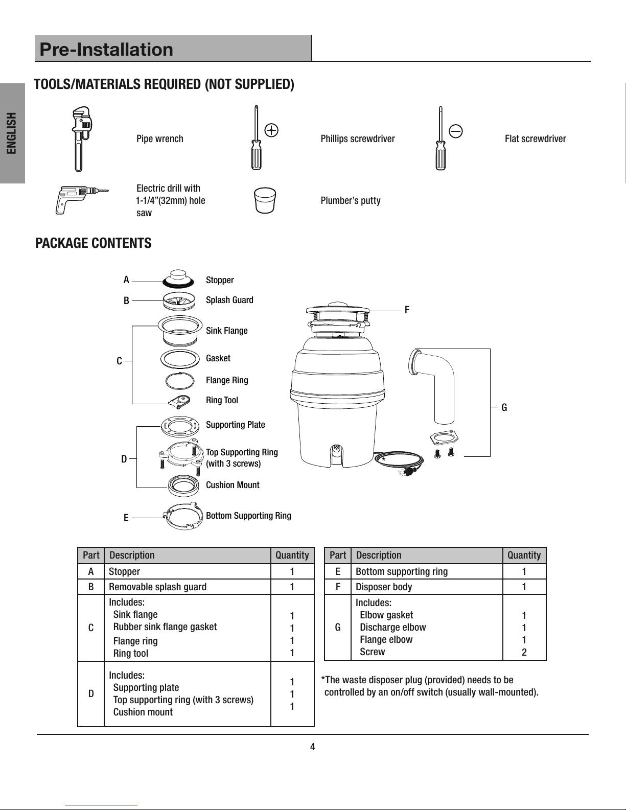
Pre-Installation
Tools/Materials Required .............................4
Package Contents ..................................4
Installation .........................................
Removal of Old Unit.................................5
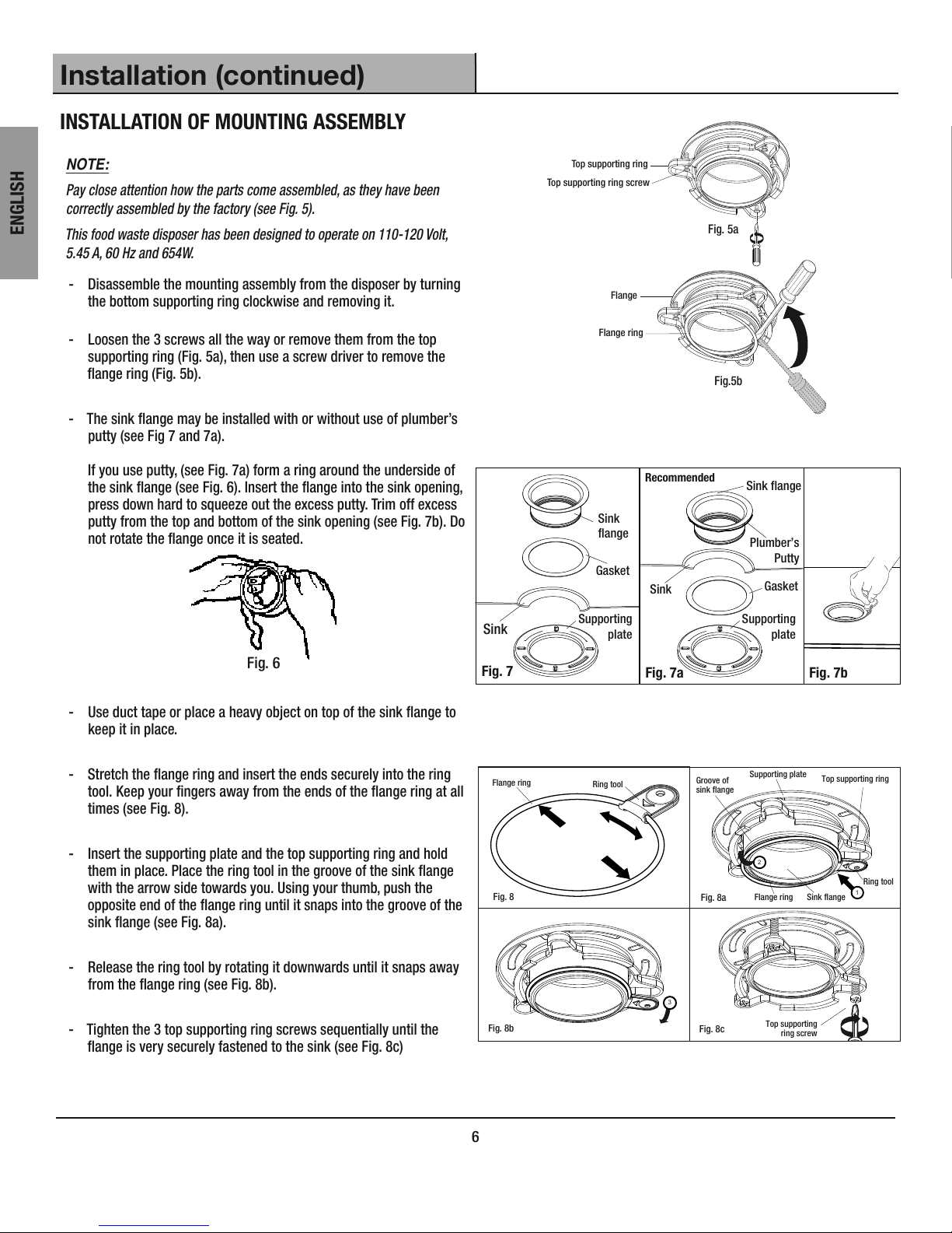
Installation of the Mounting Assembly..................6
Attaching Discharge Elbow ..........................7
Removing Knockout Plug............................7
Connecting Disposer to Mounting Assembly ..............8
Dishwasher Connection............................. 9
Electrical Connection & Grounding.....................9
Operation ........................................10
Care and Maintenance .............................10
Troubleshooting ..................................11
Service Parts .....................................12
MANUEL DE L’UTILISATEUR ..........................13
Safety Information
READ ALL INSTRUCTIONS BEFORE USING THE APPLIANCE
IMPORTANT SAFETY INSTRUCTIONS
INSTRUCTIONS PERTAINING TO A RISK OF FIRE, ELECTRIC SHOCK, OR
INJURY TO PERSONS. WARNING - WHEN USING ELECTRICAL APPLIANCES,
BASIC PRECAUTIONS SHOULD ALWAYS BE FOLLOWED, INCLUDING THE
FOLLOWING:
NOTE:
This food waste disposer has been designed to operate on 110-120 Volt,
60 Hz exclusively. Using any other voltage or Hz adversely affects its performance.
1. Inspect your unit before proceeding. Once you unpack your unit,
check for chips, scratches, cracks, dents or scuff marks. If any
damage is noticed, do not install. Please return to the place of
purchase.
2. Use this unit only in the manner intended by the manufacturer. If you
have any questions, contact the manufacturer.
3. Installation work and plumbing must be done by qualied person(s)
in accordance with all applicable codes and standards.
4. When attempting to loosen an obstruction in a waste disposer, use a
long wooden object such as a wooden spoon or the wooden handle
of a broom or a mop.
5. When attempting to remove objects from a waste disposer, use
long-handled tongs or pliers. If the disposer is magnetically actuated,
non-magnetic tools should be used.
6. When not operating a disposer, leave the drain cover (stopper) in
place to reduce the risk of objects falling into the disposer.
SAVE THESE INSTRUCTIONS
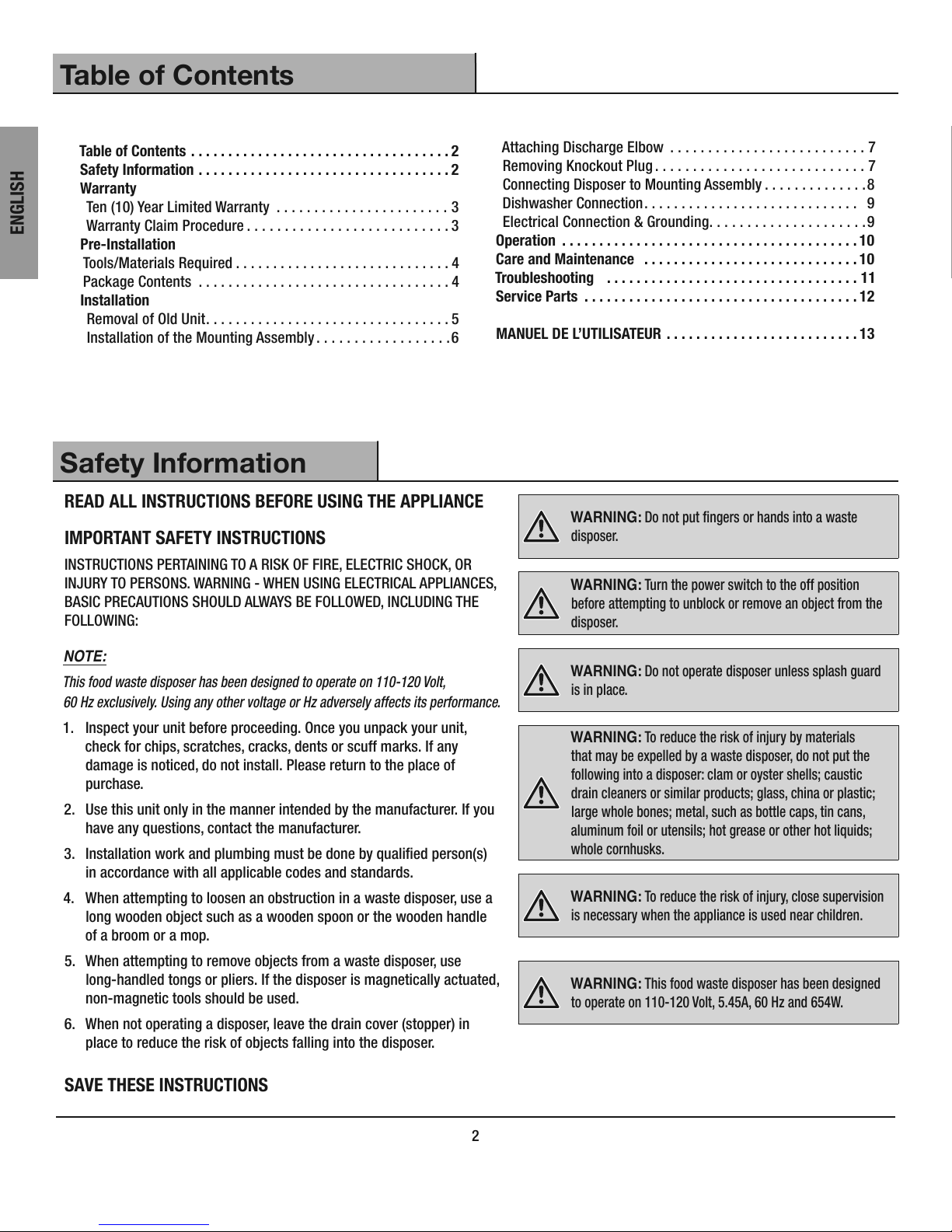
WARNING: Do not put ngers or hands into a waste
disposer.
WARNING: Turn the power switch to the off position
before attempting to unblock or remove an object from the
disposer.
WARNING: Do not operate disposer unless splash guard
is in place.
WARNING: To reduce the risk of injury by materials
that may be expelled by a waste disposer, do not put the
following into a disposer: clam or oyster shells; caustic
drain cleaners or similar products; glass, china or plastic;
large whole bones; metal, such as bottle caps, tin cans,
aluminum foil or utensils; hot grease or other hot liquids;
whole cornhusks.
WARNING: To reduce the risk of injury, close supervision
is necessary when the appliance is used near children.
WARNING: This food waste disposer has been designed
to operate on 110-120 Volt, 5.45A, 60 Hz and 654W.

3 CONGLOMKB.COM
Please contact customer.service@conglomkb.com or 1-877-333-0098 for further assistance.
ENGLISH
Warranty
TEN (10) YEAR LIMITED WARRANTY
A thorough inspection must be made before installation and any damage must be promptly reported. We will not be liable for failures or damage that
could have been discovered or avoided by proper inspection and testing prior to installation.
Conglom Kitchen & Bath warrants this product to be free from defects in materials or workmanship for ten (10) years from the date of purchase. Proof
of purchase (original sales receipt) from the original consumer purchaser must be made available to Conglom Kitchen & Bath for all warranty claims.
This warranty is non-transferable and shall be voided if the unit is removed from its initial installation or if it is not installed following the manufacturer’s
instructions. It does not apply in the event of product damage due to the use of other than genuine Conglom Kitchen & Bath replacement parts,
(Replacement parts may be obtained by e-mail at customer.service@conglomkb.com or by calling 1-877-333-0098 between 8:30 am - 5:00 pm EST)
installation error, abuse, misuse or improper care and maintenance (whether performed by a plumber, contractor, service provider or member of
the purchaser’s household). The warranty excludes damage due to aggressive air or water conditions, harsh or abrasive cleaners and/or materials.
Under no circumstance shall we be held liable for personal injury or property damage resulting from improper installation or use of this product.
We will not be held liable for inconvenience caused by loss of use of this product, costs incurred for labour or materials, removal and installation
of replacement units, or any other incidental or consequential damages. Costs relating to obtaining access for repair or replacement are the
responsibility of the user.
Our obligation shall be limited to the repair or replacement of a unit (at our discretion) that may prove, by our sole examination, to be defective under
normal use and service during the warranty period.
Any failure of this product that is not traceable to a defect in material or workmanship is not covered by this warranty. These non-warrantable items
include, but are not limited to:
- Improper installation not in accordance with manufacturer’s instructions.
- Dents and/or scratches incurred during shipping, handling, or installation.
- Damage caused by failure to follow care and cleaning guidelines.
- Alterations made to the unit by the purchaser or installer.
- Damage caused by accidental impact, re, ood, freezing, and normal wear.
- Bends and warping caused by forced connections, over-tightened ttings, and inadequate support during installation.
This warranty does not extend to commercial and institutional installation or use.
WARRANTY CLAIM PROCEDURE
If a claimable defect occurs or replacement parts are needed, please contact our customer service team at customer.service@conglomkb.com or
1-877-333-0098 (Service available in English and French, Monday - Friday from 8:30am - 5pm EST).
Before you make your call, please ensure that you have:
- Model number or description.
- Proof of sale.
- Details regarding the defect and/or part number.
- Name(s) and address(es) of the owner and/or installer.

4
ENGLISH
Pre-Installation
TOOLS/MATERIALS REQUIRED (NOT SUPPLIED)
Pipe wrench Phillips screwdriver Flat screwdriver
Electric drill with
1-1/4”(32mm) hole
saw
Plumber’s putty
PACKAGE CONTENTS
AStopper
Splash Guard
Sink Flange
Gasket
Supporting Plate
Top Supporting Ring
(with 3 screws)
Flange Ring
Ring Tool
Cushion Mount
Bottom Supporting Ring
F
B
C
E
D
G
Part Description Quantity
AStopper 1
BRemovable splash guard 1
C
Includes:
Sink ange
Rubber sink ange gasket
Flange ring
Ring tool
1
1
1
1
D
Includes:
Supporting plate
Top supporting ring (with 3 screws)
Cushion mount
1
1
1
Part Description Quantity
EBottom supporting ring 1
FDisposer body 1
G
Includes:
Elbow gasket
Discharge elbow
Flange elbow
Screw
1
1
1
2
*The waste disposer plug (provided) needs to be
controlled by an on/off switch (usually wall-mounted).
*

5 CONGLOMKB.COM
Please contact customer.service@conglomkb.com or 1-877-333-0098 for further assistance.
ENGLISH
Installation
REMOVAL OF OLD UNIT
General instructions - your model may vary.
CAUTION: Risk of electric shock. Turn off electric
power at fuse box or circuit breaker before removing
old unit.
CAUTION: Be sure to support the disposer when
removing the mounting ring or it may fall.
NOTE:
Before starting this step, turn off the electrical power at the circuit breaker
or fuse box. Unplug the disposer.
- Disconnect dishwasher if connected to the disposer.
- Use a pipe wrench to disconnect drain line where it attaches to
the disposer discharge elbow (see Fig. 1). Fig. 1
- Remove the disposer from the sink ange by turning the
mounting ring clockwise. If you are unable to turn the mounting
ring, tap on one of the extensions from the ring with a hammer.
Some mounting systems have tubular extensions, inserting a
screwdriver into one tube will provide additional leverage for
turning the mounting ring (see Fig. 2).
Some disposers may require the removal or loosening of nuts
from the mounting screws (see Fig. 3). Some disposers may
require the removal of a clamp.
NOTE:
If your disposer has the same ange as the new disposer and you would
like to keep your old ange, you may skip the following steps and skip to
page 7. If you would like to replace your existing ange or if the ange is
different, please continue with the following steps
.
Fig. 2
Fig. 3
- To remove the remaining mounting system from the sink,
loosen the mounting screws and push the mounting ring up.
Under it is the snap ring. Use a screwdriver to pop off the ring
(see Fig. 4). Remove the mounting ring, the protector ring and
the gasket from the sink ange. Some mountings will require
the unscrewing of a large ring holding the sink ange in place.
Pull the sink ange up through the sink and clean off the old
putty from the sink.
Fig. 4
NOTE:
This is a good time to clean out the trap and drain lines by running a drain
auger or plumber’s snake before installing your new disposer.

6
ENGLISH
Installation (continued)
INSTALLATION OF MOUNTING ASSEMBLY
Fig.5b
Fig. 5a
Top supporting ring
Top supporting ring screw
Flange
Flange ring
Supporting
plate
Gasket
Plumber’s
Putty
Sink flange
Recommended
Sink
Fig. 7a Fig. 7b
Supporting
plate
Gasket
Sink
flange
Sink
Fig. 7
NOTE:
Pay close attention how the parts come assembled, as they have been
correctly assembled by the factory (see Fig. 5).
This food waste disposer has been designed to operate on 110-120 Volt,
5.45 A, 60 Hz and 654W.
- Disassemble the mounting assembly from the disposer by turning
the bottom supporting ring clockwise and removing it.
- Loosen the 3 screws all the way or remove them from the top
supporting ring (Fig. 5a), then use a screw driver to remove the
ange ring (Fig. 5b).
- The sink ange may be installed with or without use of plumber’s
putty (see Fig 7 and 7a).
If you use putty, (see Fig. 7a) form a ring around the underside of
the sink ange (see Fig. 6). Insert the ange into the sink opening,
press down hard to squeeze out the excess putty. Trim off excess
putty from the top and bottom of the sink opening (see Fig. 7b). Do
not rotate the ange once it is seated.
Fig. 6
- Use duct tape or place a heavy object on top of the sink ange to
keep it in place.
- Stretch the ange ring and insert the ends securely into the ring
tool. Keep your ngers away from the ends of the ange ring at all
times (see Fig. 8).
- Insert the supporting plate and the top supporting ring and hold
them in place. Place the ring tool in the groove of the sink ange
with the arrow side towards you. Using your thumb, push the
opposite end of the ange ring until it snaps into the groove of the
sink ange (see Fig. 8a).
- Release the ring tool by rotating it downwards until it snaps away
from the ange ring (see Fig. 8b).
- Tighten the 3 top supporting ring screws sequentially until the
ange is very securely fastened to the sink (see Fig. 8c)
Top supporting ring
Ring tool
Supporting plate
Flange ring Sink flange
Groove of
sink flange
Fig. 8a 1
2
Fig. 8
3
Fig. 8b Fig. 8c
Ring tool
Flange ring
Top supporting
ring screw

7 CONGLOMKB.COM
Please contact customer.service@conglomkb.com or 1-877-333-0098 for further assistance.
ENGLISH
Installation (continued)
If at any time the bottom supporting ring becomes disengaged
from the body of the waste disposer, then:
1. Align the slot in the bottom supporting ring with tab on the
waste disposer body.
2. Lower the bottom supporting ring and make the slot t in the
tab.
3.Turn the bottom supporting ring counter clockwise to secure it
in place.
Slot
Tab
ATTACHING DISCHARGE ELBOW
Elbow Gasket Groove
Discharge Elbow
Fig. 9a
Fig. 9
- Make sure the elbow gasket is attached to the discharge elbow
correctly (see Fig. 9a).
- Connect the discharge elbow to the disposer
(see Fig. 9).
REMOVING KNOCKOUT PLUG
(SKIP THIS STEP IF YOU DO NOT HAVE A DISHWASHER)
- Using a blunt instrument (steel punch or wooden dowel),
knock out the entire plug (see Fig. 10). Do not use a
screwdriver or sharp instrument. When the knockout plug falls
into the disposer, you may remove it, or grind it up when the
disposer is being used. This will not damage the disposer in
any way, but may take some time to grind. Fig. 10
Knockout
Plug
Wood or
Metal Dowel

8
ENGLISH
Installation (continued)
CONNECTING THE DISPOSER TO THE
MOUNTING ASSEMBLY
Elbow
Trap
Fig. 11
Fig. 12
Disposer body
Reset Button
Fig.13
Top
supporting
ring
Bottom
supporting
ring
Tab
Tool
Mount
Step
Sink
Mounting
Assembly
Cushion Mount
Fig.13a
Sink
Tool Mount
- Adjust the disposer position to make the elbow line up with the
trap (see Fig. 11).
- The disposer must be installed so that the reset button is
readily accessible (see Fig. 12).
- Make sure the cushion mount is properly in place. Line up
the disposer under the mounting assembly. Lift and guide the
disposer so that all three tabs of the bottom supporting ring
engage the steps of the top supporting ring. Turn the bottom
supporting ring counter-clockwise until it is fully engaged and
the tool mount comes in contact with the top supporting ring.
Insert a screw driver into the tool mount for added leverage, if
needed (see Fig 13a).
If you are unable to fully engage the bottom supporting ring,
release and lower the waste disposer (see Fig 13b).
Fig. 13b

9 CONGLOMKB.COM
Please contact customer.service@conglomkb.com or 1-877-333-0098 for further assistance.
ENGLISH
Installation (continued)
Turn the bottom supporting ring 1/3 of a turn counter-clockwise
and repeat the mounting procedure described above (see Fig 13c).
1/3 turn
Fig. 13c
- Connect the bottom of the elbow to the trap by tightening the
slip nut (Fig. 14).
- Run water and check all connections for leaks.
Fig. 14
DISHWASHER CONNECTION
Fig. 15
*Air Gap
Drain
Disposer
Rubber Hose
Dishwasher Hose
- Connect the dishwasher hose (see Fig. 15) using a hose clamp.
Make sure all plumbing connections are tight. Run water and
check for leaks.
*Air Gap may not be required for all installations, verify your
local plumbing codes.
ELECTRICAL CONNECTION & GROUNDING
- Connect the disposer to the appropriate household current only.
WARNING: Improper connection of the equipment-
grounding conductor can result in a risk of electric shock.
Check with a qualied electrician or serviceman if you
are not sure. Do not modify the plug provided with the
appliance if it does not t the outlet. Have a proper outlet
installed by a qualied electrician.
NOTE: The waste disposer plug provided needs to be
controlled by an on/off switch (usually wall-mounted).
- This appliance must be grounded. In the event of a malfunction
or breakdown, grounding provides a path of least resistance
for electric current to reduce the risk of electric shock. This
appliance is equipped with a cord having an equipment-
grounding conductor and a grounding plug. The plug, supplied
with this unit, must be connected to an appropriate outlet that
is properly installed, switched and grounded in accordance
with all local codes and ordinances. If the supply cord is
damaged it must be replaced by the manufacturer or a
qualied person in order to avoid a hazard.

10
ENGLISH
Operation
TESTING AND OPERATION
- Remove sink stopper. Turn on a medium ow of cold water.
TIPS FOR SUCCESSFUL OPERATION
- Turn switch to ON position; your motor is turning at full speed
and ready to use. - Be sure disposer is empty before using your dishwasher so
it may drain properly.
- You may want to leave the stopper in the drain when not in
use to prevent utensils and foreign objects from falling into
the disposer.
- Your disposer is ruggedly built to give you many years of
trouble free service. It will handle all normal food wastes,
but it will NOT grind or dispose of such items as plastic, tin
cans, bottle caps, glass, china, leather, cloth, rubber, string,
clam and oyster shells, aluminum foil or feathers.
- Slowly insert food waste into disposer (table scraps, peelings,
rinds, seeds, pits, small bones and coffee grounds). To speed
up food waste disposal, cut or break up large bones, rinds
and cobs. Large bones and brous waste require considerable
grinding time and are more easily thrown away with other
trash. Do not be alarmed that the disposer slows down while
grinding. The disposer is actually increasing torque (grinding
power) and is operating under normal conditions.
- Before turning disposer off, let water and disposer run for
approximately 15 seconds after shredding or grinding stops.
This assures that all waste is throroughly ushed through trap
and drain.
- It is not recommended to use hot water while running disposer.
Cold water will keep waste and fats solid so disposer can ush
away particles.
NOTE:
The anti-jam swivel impellers make a clicking sound as they initially swing
into place. This indicates normal operation.
Care and Maintenance
DO NOT ATTEMPT TO LUBRICATE YOUR DISPOSER!
The motor is permanently lubricated. The disposer is self cleaning and
scours its internal parts with each use. NEVER put lye or chemical
drain cleaners into the disposer, as they cause serious corrosion of
metal parts. If used, resulting damage can be easily detected and all
warranties are void. Mineral deposits from your water can form on the
stainless steel turntable, giving the appearance of rust. DO NOT BE
ALARMED, the stainless steel turntables used will not corrode.
GENERAL INSTALLATION DIMENSIONS
8.7 in
5.7 in
14.1 in
7.1 in
4.5 in
SINGLE BOWL
approx 10 1/8”
DOUBLE BOWL CENTER OUTLET
approx 10 1/8”
DOUBLE BOWL END OUTLET
approx 10 1/8”

11 CONGLOMKB.COM
Please contact customer.service@conglomkb.com or 1-877-333-0098 for further assistance.
ENGLISH
Troubleshooting
Before seeking repair or replacement, we recommend that you review the following:
Problem Solution
The disposer is making loud noises. - Other than the noises during grinding of small bones and fruit pits,
these are usually caused by accidental entry of a spoon, bottle cap
or other foreign objects. To correct this, unplug the power cord, turn
off the electricity and water. After the disposer has stopped, remove
the splash guard, remove the object with long handled tongs, and
replace the splash guard.
The disposer does not start. - Unplug the power cord and turn either the wall switch or breaker
box switch to “OFF” position, depending on your model and wiring
conguration. Remove the stopper and/or the splash guard. Check
to see if turntable will rotate freely using a wooden spoon handle.
If turntable rotates freely, replace the splash guard and check the
reset button to see if it has been tripped. The reset button is red and
is located on the front end of the disposer. Push the button in until it
clicks and remains depressed.
- If the reset button has not been tripped, check for a shorted or
broken wire connecting to the disposer. Check the electrical power
switch, fuse box or circuit breaker. If the wiring and electrical
components are intact, the unit may have internal problems that
require servicing or a replacement.
The turntable does not rotate freely. - Unplug the power cord and turn either the wall switch or breaker
box switch to “OFF” position, depending on your model and wiring
conguration. Then check for any foreign objects lodged between
the turntable and the grind ring. Dislodge the object by rotating
the table with a wooden spoon handle and remove the object. If no
foreign object is present, there may be internal problems.
The disposer leaks. - If the unit leaks at the top, it may be due to:
1) Improper seating of the sink ange (gasket centering, putty or
tightening);
2) The support ring is not tightened properly;
3) Defective or improper installation for the cushion mount.
- If the unit leaks at the waste elbow, the leak may be due to improper
tightening of the elbow ange screws.

12
ENGLISH
Service Parts
If you are missing parts or if you require replacement parts, please contact our customer service team at customer.service@conglomkb.com or
1-877-333-0098 (Service available in English and French, Monday - Friday from 8:30am - 5pm EST). Identify the required part(s) and have the part
number(s) ready.
A
B
E
F
Sink Flange
Gasket
Supporting Plate
Top Supporting Ring
(with 3 screws)
Flange Ring
Cushion Mount
C
D
Ring Tool
Part Description Code Quantity
AStopper QHG108 1
BRemovable splash guard QHG114 1
C
Includes:
Sink ange
Rubber sink ange gasket
Flange ring
Ring tool
QHG115
1
1
1
1
D
Includes:
Supporting plate
Top supporting ring (with 3 screws)
Cushion mount
QHG117
1
1
1
1
EBottom supporting ring QHG112 1
F
Includes:
Elbow gasket
Discharge elbow
Flange elbow
Screw
QHG106
1
1
1
2

13 CONGLOMKB.COM
Veuillez contacter customer.service@conglomkb.com ou 1-877-333-0098 pour toute assistance supplémentaire.
FRANÇAIS
Table des matières
OWNER’S MANUAL ..................................2
Table des matières .................................13
Consignes de sécurité ..............................13
Garantie ...........................................
Garantie limité de dix (10) ans.......................14
Procédure de réclamation pour la garantie .............14
Préinstallation
Outils/matériaux requis .............................15
Contenu de l’emballage .............................15
Installation .........................................
Démontage de l’ancien appareil ......................16
Installation de l’ensemble de montage ................17
Connecter le coude d’évacuation.....................18
Enlever le coude d’évacuation.......................18
Raccorder l’appareil à l’ensemble du montage...........19
Raccordement au lave-vaisselle ..................... 20
Raccordement électrique...........................20
Fonctionnement ...................................21
Soin et nettoyage .................................21
Dépannage ......................................22
Pièces de rechange ................................23
Consignes de sécurité
LIRE ET CONSERVER CES DIRECTIVES
AVERTISSEMENT - AFIN DE RÉDUIRE LES RISQUES D’INCENDIE,
DE CHOC ÉLECTRIQUE OU DE BLESSURES, VEUILLEZ PRENDRE
CONNAISSANCE DES DIRECTIVES SUIVANTES :
REMARQUE :
Ce broyeur à déchets a été conçu de façon à fonctionner sur un circuit
électrique de 110-120 volts, 60Hz uniquement. L’utiliser sur tout autre type
de circuit électrique peut affecter sa performance.
1. Vérier soigneusement l’unité avant l’installation pour vous
assurer qu’elle ne comporte aucun dommage. Une fois
que vous déballez votre unité, vériez pour les rayures, les
ssures, les bosses ou les éraures. Si des dommages sont
notés, le retourner au commerce où l’achat a été effectué.
2. Cet appareil ne peut être utilisé autrement que pour l’usage
prévu par le fabricant. Consulter le fabricant pour toutes
questions concernant l’appareil.
3. L’installation et le raccordement de la plomberie doivent être
faits par une (des) personne(s) qualiée(s), conformément
aux codes et normes de construction.
4. Lorsque vous tentez de dégager une obstruction dans le
broyeur à déchets, utilisez un objet long en bois tel qu’une
cuillère en bois ou le manche en bois d’un balais ou d’une
vadrouille.
5. Lorsque vous tentez de retirer un objet obstruant le broyeur à
déchets, utilisez des pinces à long manche. Si le broyeur est
actionné de manière magnétique, des outils non métalliques
devront êtres utilisés.
6. Lorsque le broyeur n’est pas utilisé, laissez le bouchon de
drain en place an de réduire le risque qu’un objet tombe
dans le broyeur.
AVERTISSEMENT : Ne mettez pas vos doigts ou vos
mains dans le broyeur.
AVERTISSEMENT : Éteignez l’appareil en mettant
l’interrupteur en position ‘OFF’ avant de tenter de débloquer
ou d’enlever tout objet du broyeur.
AVERTISSEMENT : Ne faites pas fonctionner le broyeur
sans que l’écran anti-éclaboussure soit en place.
AVERTISSEMENT : An de réduire le risque de blessure
par des objets pouvant être expulsés par le broyeur, ne
mettez pas les objets suivants dans le broyeur : Coquilles
de palourde ou de moule, débouche-conduit liquide corrosif
ou produits similaires; verre, porcelaine ou plastique; de
grands os; métal, tel que des capsules de bouteille, boites
de conserve, papier d’aluminium ou ustensiles; tout corps
gras chaud ou autres liquides chauds; épis de maïs complet.
AVERTISSEMENT : An de réduire le risque de blessure,
une supervision est nécessaire lorsque l’appareil est en
marche près des enfants.
AVERTISSEMENT : Ce broyeur à déchets a été conçu
pour fonctionner uniquement dans une prise de 110-120
volts, 5.45A, 60Hz et 654W.

14
FRANÇAIS
Garantie
GARANTIE LIMITÉE DE DIX ANS
Inspecter minutieusement le produit avant l’installation et signaler tout dommage sans délai. Nous ne serons pas responsables des défaillances
ou des dommages qui auraient dû être découverts ou évités par une inspection adéquate et des essais avant l’installation.
Conglom Kitchen and Bath garantit ce produit contre tout défaut dans les matériaux ou la fabrication, pour une période de dix (10) ans à
compter de la date de l’achat. Une preuve d’achat (facture d’achat originale) du consommateur/acheteur original devra accompagner toute
réclamation faite à Conglom Kitchen & Bath.
Cette garantie est non transférable et sera nulle si l’unité est enlevée de son installation initiale ou si elle n’est pas installée suivant les
spécications du fabricant. Elle ne s’applique pas dans l’éventualité de dommages causés au produit suite à l’utilisation de pièce(s) de
rechange autre que les pièces originales Conglom Kitchen and Bath, (les pièces de rechange peuvent être obtenues en nous écrivant un
courriel à customer.service@conglomkb.com ou en appelant au 1-877-333-0098 entre 8 h 30 et 17 h, H.N.E.) une erreur d’installation, l’abus,
l’utilisation ou l’entretien incorrect et le service incorrect (qu’ils soient effectués par un plombier, un entrepreneur, une entreprise de service ou
un membre de la famille de l’acheteur). La garantie exclut les dommages causés par des conditions agressives d’air ou d’eau, des nettoyants
ou des matériaux rudes et/ou abrasifs.
Nous ne pouvons en aucun cas être tenus responsables pour toute blessure corporelle ou tout dommage matériel résultant d’une mauvaise
installation ou utilisation de ce produit. Nous ne serons pas tenus responsables de l’incapacité d’utiliser cette unité, des inconvénients, des
coûts encourus pour la main-d’oeuvre, des matériaux, de l’enlèvement et de l’installation des unités de remplacement ou d’aucun autre
dommage causé par un incident ou accessoire. Les coûts encourus pour obtenir l’accès pour la réparation ou le remplacement sont la
responsabilité de l’utilisateur.
Nos obligations se limitent à la réparation ou au remplacement de l’unité (selon notre discrétion) qui peut s’avérer, selon notre examen unique,
être défectueuse sous l’utilisation et le service normaux pendant la période de garantie. Nous pouvons émettre un crédit au montant de la
valeur de la facture du produit défectueux (ou d’un pourcentage de ce montant selon l’usure) tenant lieu de la réparation ou du remplacement.
Toute défectuosité de l’unité qui ne peut être liée à un défaut de matériel ou de fabrication n’est pas couverte par cette garantie. Ces conditions
non garanties incluent, mais ne se limitent pas aux suivantes :
- Une mauvaise installation non conforme aux instructions du fabricant;
- Les bosselures, bosses et rayures causées pendant l’expédition, la manutention ou l’installation;
- Le changement de la couleur ou du ni en raison de l’usage d’un produit chimique;
- Les dommages causés par le non-respect des instructions de soin et de nettoyage, y compris les dommages causés par l’utilisation
de produits nettoyants abrasifs;
- Toute modication apportée à l’unité par l’acheteur ou l’installateur;
- Les dommages en raison d’un impact accidentel, du feu, d’une inondation, du gel et de l’usure normale;
- Les courbures et les déformations provoquées par des raccordements forcés, des xations trop serrées et un support inadéquat
pendant l’installation.
PROCÉDURE DE RÉCLAMATION POUR LA GARANTIE
Si un défaut couvert par la garantie se produit ou que vous avez besoin des pièces de rechange, contacter notre service à la clientèle au customer.
service@conglomkb.com ou au 1-877-333-0098 (service disponible en anglais et français du lundi au vendredi de 8 h 30 à 17 h, H.N.E.).
Avant d’appeler, veuillez-vous assurer d’avoir en main :
- Le numéro de modèle ou une description;
- La preuve d’achat;
- Les détails concernant le défaut et/ou le numéro de la pièce de rechange;
- Le nom et l’adresse du propriétaire et/ou de l’installateur.

15 CONGLOMKB.COM
Veuillez contacter customer.service@conglomkb.com ou 1-877-333-0098 pour toute assistance supplémentaire.
FRANÇAIS
Préinstallation
OUTILS/MATÉRIAUX REQUIS (NON INCLUS)
Clé à tuyau Tournevis Phillips Tournevis plat
Perceuse électrique
avec une scie-cloche
de 32mm (1-1/4 po)
Mastic
CONTENU DE L’EMBALLAGE
ABouchon
Écran anti-éclaboussure
Bride d’évier
Joint de la bride
Plaque de montage
Collier de serrage
(incluant 3 vis)
Rondelle
Outil à joint torique
Joint amortisseur
Bague de montage
F
B
C
E
D
G
Pièce Description Quantité
ABouchon 1
BÉcran anti-éclaboussure 1
C
Inclus :
Bride d’évier
Joint de la bride
Rondelle
Outil à joint torique
1
1
1
1
D
Inclus :
Plaque de montage
Collier de serrage (incluant 3 vis)
Joint amortisseur
1
1
1
Pièce Description Quantité
EBague de montage 1
F Corps du broyeur 1
G
Inclus :
Joint du coude
Coude d’évacuation
Bride de serrage
Vis
1
1
1
2
*Le cordon électrique fourni avec cette unité doit
être branché à une prise murale contrôlée par un
interrupteur.
*

16
FRANÇAIS
Installation
DEMONTAGE DE L’ANCIEN APPAREIL
Les instructions peuvent varier selon le modèle.
PRUDENCE : Éteignez l’appareil en mettant
l’interrupteur en position ‘OFF’ avant de tenter de
débloquer ou d’enlever tout objet du broyeur.
PRUDENCE : Assurez-vous de soutenir l’appareil
lorsque vous enlevez la bague de montage ou il
pourrait tomber.
REMARQUE :
Avant de débuter cette étape, coupez l’alimentation électrique de la boîte
de disjoncteurs ou de fusibles. Débranchez l’ancien broyeur.
- Déconnectez le lave-vaisselle du broyeur.
- Utilisez une clé à tuyau an de déconnecter le drain relié au
coude du broyeur (voir Fig. 1).
Fig. 1
- Retirez le broyeur de la bride d’évier en tournant la bague de
montage dans le sens des aiguilles. S’il vous est impossible de
tourner la bague, frappez sur l’une des extrémités de la bague
à l’aide d’un marteau. Certains systèmes de montage ont des
extrémités tubulaires, vous pourrez donc insérer un tournevis
dans l’un des tubes an de fournir un levier supplémentaire
pour faire tourner la bague de montage (voir Fig. 2).
Certains broyeurs nécessiteront que l’on enlève ou que l’on
desserre les écrous des vis de montage (voir Fig. 3), et pour
certains il sera nécessaire d’enlever la bride de serrage.
REMARQUE :
Si votre broyeur possède la même bride que le nouveau broyeur ou si
vous désirez conserver votre ancienne bride, vous pouvez poursuivre
directement à la page 18. Toutefois, si vous désirez remplacer votre bride
existante ou si la bride est différente, poursuivez avec les étapes suivantes.
Fig. 2
Fig. 3
- Pour enlever le reste du montage actuel de l’évier, desserrez
les vis de montage et poussez la bague de montage vers le
haut. Le jonc de blocage se trouve en-dessous. Utilisez un
tournevis pour enlever le jonc (voir Fig. 4). Enlevez la bague
de montage, l’anneau de protection et le joint d’étanchéité de
la bride de l’évier. Certains montages nécessitent le dévissage
d’un gros anneau qui tient en place la bride de l’évier. Tirez la
bride vers le haut du trou de l’évier et nettoyez l’ancien mastic
de l’évier
Fig. 4
REMARQUE:
Protez de cette occasion pour nettoyer les conduits d’évacuation à l’aide
d’un furet ou d’une sonde spirale avant d’installer le nouveau broyeur à déchets.

17 CONGLOMKB.COM
Veuillez contacter customer.service@conglomkb.com ou 1-877-333-0098 pour toute assistance supplémentaire.
FRANÇAIS
Installation (suite)
INSTALLATION DE L’ENSEMBLE DE MONTAGE
Fig.5b
Fig. 5a
Collier de serrage
Vis du collier de serrage
Bride
Rondelle
Plaque de
montage
Joint de
la bride
Mastic
Bride
d’évier
Conseillé
Évier
Fig. 7a Fig. 7b
Plaque de
montage
Joint de
la bride
Bride
d’évier
Évier
Fig. 7
REMARQUE :
Portez une attention particulière à l’ordre d’assemblage des composantes
puisqu’elles ont été correctement assemblées en usine.
Ce broyeur à déchets a été conçu pour fonctionner uniquement dans une
prise de 110-120 volts, 5.45A, 60Hz et 654W.
- Démontez le système d’ancrage du broyeur en tournant la bague
de montage dans le sens des aiguilles d’une montre et enlevez-le.
- Dévissez les 3 vis complètement ou enlevez-les de la bague de
montage (voir Fig. 5a). Puis, utilisez un tournevis an d’enlever le
collier de serrage (voir Fig. 5b).
- La bride de l’évier peut être installée avec ou sans l’utilisation de
mastic (voir Fig. 7 et 7a).
Si vous utilisez du mastic (voir Fig 7a), formez une couronne de
mastic autour de la partir inférieure de la bride de l’évier (voir
Fig.6). Insérez la bride dans le trou de l’évier et et appuyez très
fort sur la bride pour faire sortir l’excédent de mastic. Enlever
l’excédent de mastic à l’aide d’un couteau à ras du bord inférieur
du trou de l’évier en dessous et au-dessus.
Fig. 6
- Utilisez du ruban adhésif épais ou placez un objet lourd sur la
bride de l’évier an de la garder en place.
- Étirez l’anneau de caoutchouc de la bride et insérez un côté dans
l’outil à joint torique. Gardez vos doigts éloignés de l’extrémité de
l’anneau de la bride en tout temps (voir Fig. 8).
- Insérez le collier de serrage et la bague de montage et les tenir en
place. Placez l’outil à joint torique dans la rainure de la bride de
l’évier tout en ayant la èche vers vous. En utilisant votre pouce,
poussez vers le côté opposé de l’anneau de la bride jusqu’à ce
qu’il s’emboîte dans la rainure de la bride de l’évier (voir Fig. 8a).
- Relâchez l’anneau en le tournant vers le bas jusqu’à ce qu’il
s’éloigne de la bride de l’évier (voir Fig. 8b).
- Resserrez les 3 vis du collier de serrage en alternance jusqu’à ce
que la bride soit solidement attachée à l’évier (voir Fig. 8c).
Collier de serrage
Outil à
joint
torique
Plaque de montage
Joint de la bride Bride d’évier
Rainure de
la bride
Fig. 8a 1
2
Fig. 8
3
Fig. 8b Fig. 8c
Outil à joint torique
Joint de la bride
Vis du collier
de serrage

18
FRANÇAIS
Installation (suite)
Si à n’importe quel moment le collier de serrage se desserrait de
l’appareil :
1. Enlignez les encoches de la bague de montage avec les attaches
de l’appareil.
2. Abaissez la bague de montage et insérer les attaches dans les
encoches.
3.Tourner le collier de serrage dans le sens des aiguilles d’une
montre an de le sécuriser en place.
Encoche
Attache
CONNECTER LE COUDE D’ÉVACUATION
Joint du coude Rainure
Coude d’évacuation
Fig. 9a
Fig. 9
- Assurez-vous que le joint du coude d’évacuation est installé sur
le coude correctement (voir Fig. 9a).
- Connectez le coude d’évacuation au broyeur (voir Fig. 9).
ENLEVER LE BOUCHON DÉFONÇABLE
(SAUTER CETTE ÉTAPE SI VOUS N’AVEZ PAS UN LAVE-VAISSELLE)
- À l’aide d’un outil arrondi (poinçon d’acier ou goujon en bois),
faites tomber le bouchon (voir Fig. 10). Ne vous servez pas
d’un tournevis ou d’un outil tranchant. Lorsque le bouchon
tombe dans le broyeur, vous pouvez le retirer ou le broyer
lorsque le broyeur sera en marche. Il sera broyé sans risque
pour le broyeur, mais l’opération pourrait prendre un certain
temps. Fig. 10
Bouchon
défonçable
Poinçon d’acier ou
goujon en bois

19 CONGLOMKB.COM
Veuillez contacter customer.service@conglomkb.com ou 1-877-333-0098 pour toute assistance supplémentaire.
FRANÇAIS
Installation (suite)
RACCORDER L’APPAREIL À L’ENSEMBLE
DU MONTAGE
Fig. 11
Coude d’évacuation
Siphon
Fig. 12
Corps du
broyeur
Bouton de
réinitialisation
Fig.13
Collier de
serrage
Bague de
montage Encoche
Crochet
de
montage
Rebord
Évier
Ensemble
du montage
Joint amortisseur
Fig.13a
Évier
Crochet de
montage
- Ajuster le broyeur sous le système de montage an d’avoir le
coude d’évacuation aligné avec le siphon.
- Le broyeur doit être installé de façon à ce que le bouton de
réinitialisation soit facile d’accès (voir g. 12).
- Assurez-vous que le joint amortisseur soit bien en place.
Alignez le broyeur sous l’ensemble de montage. Soulevez
et guidez le broyeur de façon à avoir les 3 attaches de la
bague de montage qui s’accrochent sur chacun des trois
rebords du collier de serrage. Tourner la bague de montage
dans le sens contraire des aiguilles d’une montre jusqu’à ce
que l’appareil soit totalement accroché au collier de serrage.
Insérer un tournevis dans les attaches pour ajouter un levier
supplémentaire durant l’installation au besoin (voir Fig. 13a).
Si vous êtes incapable d’effectuer le montage complet sur le collier
de serrage, relâchez et redescendez l’appareil (voir Fig. 13b).
Fig. 13b

20
FRANÇAIS
Installation (suite)
Tournez la bague de montage d’un tiers de tour dans le sens
contraire des aiguilles d’une montre et répétez la procédure de
montage décrite précédemment (voir Fig. 13c).
un tiers (1/3) de tour
Fig. 13c
- Reliez l’extrémité inférieure du coude d’évacuation au
collecteur en serrant l’écrou (voir g. 14).
- Faites couler l’eau et vériez l’étanchéité de l’installation.
Fig. 14
RACCORDEMENT AU LAVE-VAISSELLE
Fig. 15
*
Tirant d’air
Siphon
Broyeur
Tuyau exible
Tuyau exible
lave-vaisselle
- Raccorder le tuyau exible du lave-vaisselle (voir g. 15)
à l’aide d’une bride de serrage. Vériez l’étanchéité et la
conformité de tous les raccordements de plomberie. Faites
couler l’eau et vériez l’étanchéité.
*Un tirant d’air n’est pas nécessairement requis pour toutes les
installations, vériez avec vos standards de plomberie locaux.
RACCORDEMENT ÉLECTRIQUE
- Ce broyeur est conçu pour une utilisation domestique avec
branchement sur le réseau électrique standard seulement.
AVERTISSEMENT : Un raccordement incorrect de
l’équipement de mise à la terre peut entraîner des risques
d’électrocution. Consultez un électricien ou un réparateur
si vous n’êtes pas totalement sûr que l’appareil soit
correctement mis à la terre. Ne modiez pas la che
fournie avec l’appareil si elle ne peut se brancher à la
prise de courant. Utilisez une prise de courant adéquate
installée par un électricien qualié.
REMARQUE : Le cordon électrique fourni avec cette
unité doit être branché à une prise murale contrôlée par
un interrupteur.
- Cet appareil doit être mis à la terre. Dans le cas d’une
défectuosité ou d’une panne, la mise à la terre permet de
réduire les risques d’électrocution. Cet appareil est équipé
d’un cordon d’alimentation muni d’un conducteur de mise
à la terre et d’une che de mise à la terre. La che doit être
branchée dans une prise de courant adéquatement installée
et mise à la terre conformément aux réglements locaux. Si le
cordon d’alimentation est endommagé, il doit être remplacé
par le fabricant, son répresentant ou une personne qualiée de
façon à éviter tout risque d’électrocution. L’appareil doit être
installé de façon à ce que le bouton de remise en marche soit
facilement accessible.
Table of contents
Languages:
Other Westinghouse Garbage Disposal manuals
Popular Garbage Disposal manuals by other brands

GE
GE Disposall GFC320 Series Owner's manual and installation instructions

Mullex
Mullex BOXX 40-R Assembly instructions and template

Whirlpool
Whirlpool GC2000PE1 parts manual

disperator
disperator EXCELLENT 500A-BASIC user manual

KitchenAid
KitchenAid IMPERIAL KCDI075V installation instructions

Salvajor
Salvajor Trough Collector S419 Installation & operating instructions