616000014-0 Rev. 230412-0
10-18
Il presente documento non può essere riprodotto né portato a conoscenza di terzi senza autorizzazione della ditta Omvl S.p.a.
This document may not be reproduced or made known to any third party without permission of the company Omvl S.p.a.
616000014-0 Rev. 230412-0 9-18
Il presente documento non può essere riprodotto né portato a conoscenza di terzi senza autorizzazione della ditta Omvl S.p.a.
This document may not be reproduced or made known to any third party without permission of the company Omvl S.p.a.
Come vericare quale cablaggio stacca iniettori utilizzare
Esistono diversi tipi di cablaggi stacca iniettori da abbinare alla centralina di iniezione.
N.B.: il cablaggio stacca iniettori va ordinato separartamente, non è compreso nel kit.
Per sapere quale cablaggio stacca iniettori utilizzare occorre vericare prima di tutto, sul connettore
dell’iniettore benzina, su quale PIN arriva il positivo degli iniettori.
Per identicare quale dei due li sia il positivo, seguire queste istruzioni:
- staccare tutti i connettori dagli iniettori;
- prendere un multimetro impostarlo per la lettura della tensione in continua;
- mettere il puntale negativo a massa;
- mettere il puntale positivo in uno dei due contatti del cablaggio iniettori;
- inserire il quadro e controllare immediatamente se arrivano +12 volt.
Se arrivano i +12 volt, questo è il positivo.
ATTENZIONE: il +12 volt iniettori su alcune vetture potrebbe essere temporizzato quindi
dopo alcuni secondi dall’accensione del quadro potrebbe venire a mancare. Consigliamo di
vericare la polarità di tutti i connettori del cablaggio iniettori, in modo da vericare che tutti
siano polarizzati allo stesso modo.
ESEMPI DI CONNETTORI UTILIZZATI PIÚ COMUNEMENTE
SA144 - SA144INV per vetture 4 cilindri
I cablaggi Cod. SA144 e Cod. SA144INV sono provvisti di connettori tipo “BOSCH” da collegare
direttamente sugli iniettori benzina, per determinare se usare il modello Cod. SA144 o Cod.
SA144INV bisogna vericare la polarizzazione sul cablaggio iniettori benzina:
Cod. SA144: va utilizzato se il positivo degli iniettori benzina è sul PIN A e il negativo sul PIN
B, fare riferimento alla g. 1.
Cod. SA144INV: va utilizzato se il positivo degli iniettori benzina è sul PIN B e il negativo sul
PIN A, fare riferimento alla g. 1.
SA144J - SA144JINV - SA144SJ per vetture 4 cilindri
I cablaggi Cod. SA144J e Cod. SA144JINV sono provvisti di connettori tipo “JAPAN” da colle-
gare direttamente sugli iniettori benzina, per determinare se usare il modello Cod. SA144J o
Cod. SA144JINV bisogna vericare la polarizzazione sul cablaggio iniettori benzina:
Cod. SA144J: va utilizzato se il positivo degli iniettori benzina è sul PIN A e il negativo sul PIN
B, fare riferimento alla g. 2.
Cod. SA144JINV: va utilizzato se il positivo degli iniettori benzina è sul PIN B e il negativo sul
PIN A, fare riferimento alla g. 2.
Il cablaggio Cod. SA144SJ è provvisto di spinette tipo JAPAN e di cablaggio allungato per po-
terlo installare su vetture SUBARU con motore BOXER. Va utilizzato SOLO se il positivo degli
iniettori benzina è sul PIN B e il negativo sul PIN A, fare riferimento alla g. 2.
SA144E
Il cablaggio SA144E è provvisto di un unico connettore a 6 contatti; è possibile utilizzarlo su alcuni tipi
di vetture Fiat, Citroën o Peugeot che utilizzano lo stesso connettore sul cablaggio degli iniettori.
Per l’installazione e per sapere su quali vetture è possibile utilizzarlo seguire le istruzioni
allegate al cablaggio.
SA143 - SA143INV per vetture 3 cilindri
I cablaggi Cod. SA143 e Cod. SA143INV sono provvisti di connettori tipo “BOSCH” da collegare di-
rettamente sugli iniettori benzina, per determinare se usare il modello Cod. SA143 o Cod. SA143INV
bisogna vericare la polarizzazione sul cablaggio iniettori benzina:
Cod. SA143: va utilizzato se il positivo degli iniettori benzina è sul PIN A e il negativo sul PIN B, fare
riferimento alla g. 1.
Cod. SA143INV: va utilizzato se il positivo degli iniettori benzina è sul PIN B e il negativo sul PIN A,
fare riferimento alla g. 1.
Fig. 1
B
A
Fig. 2
B
A
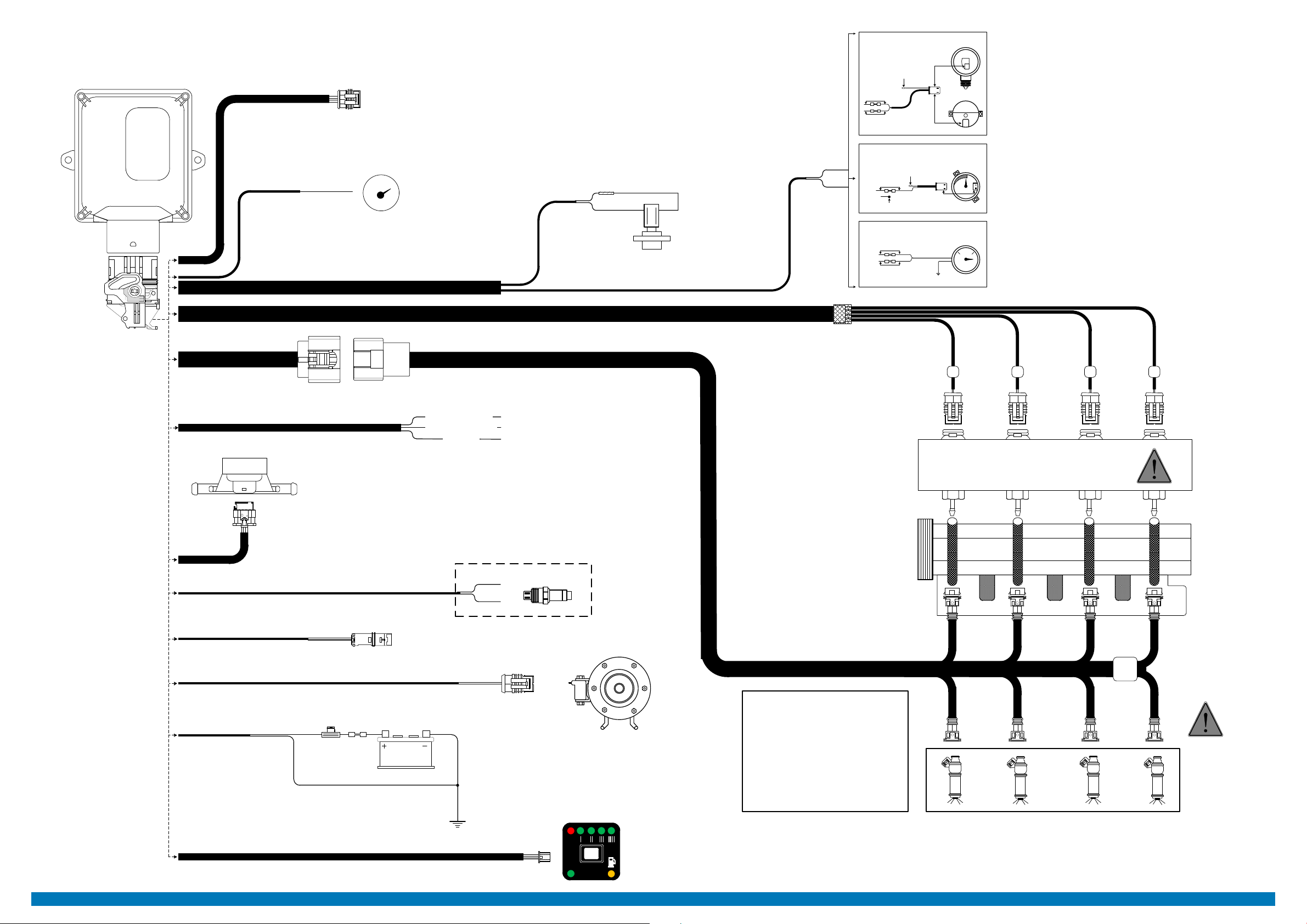
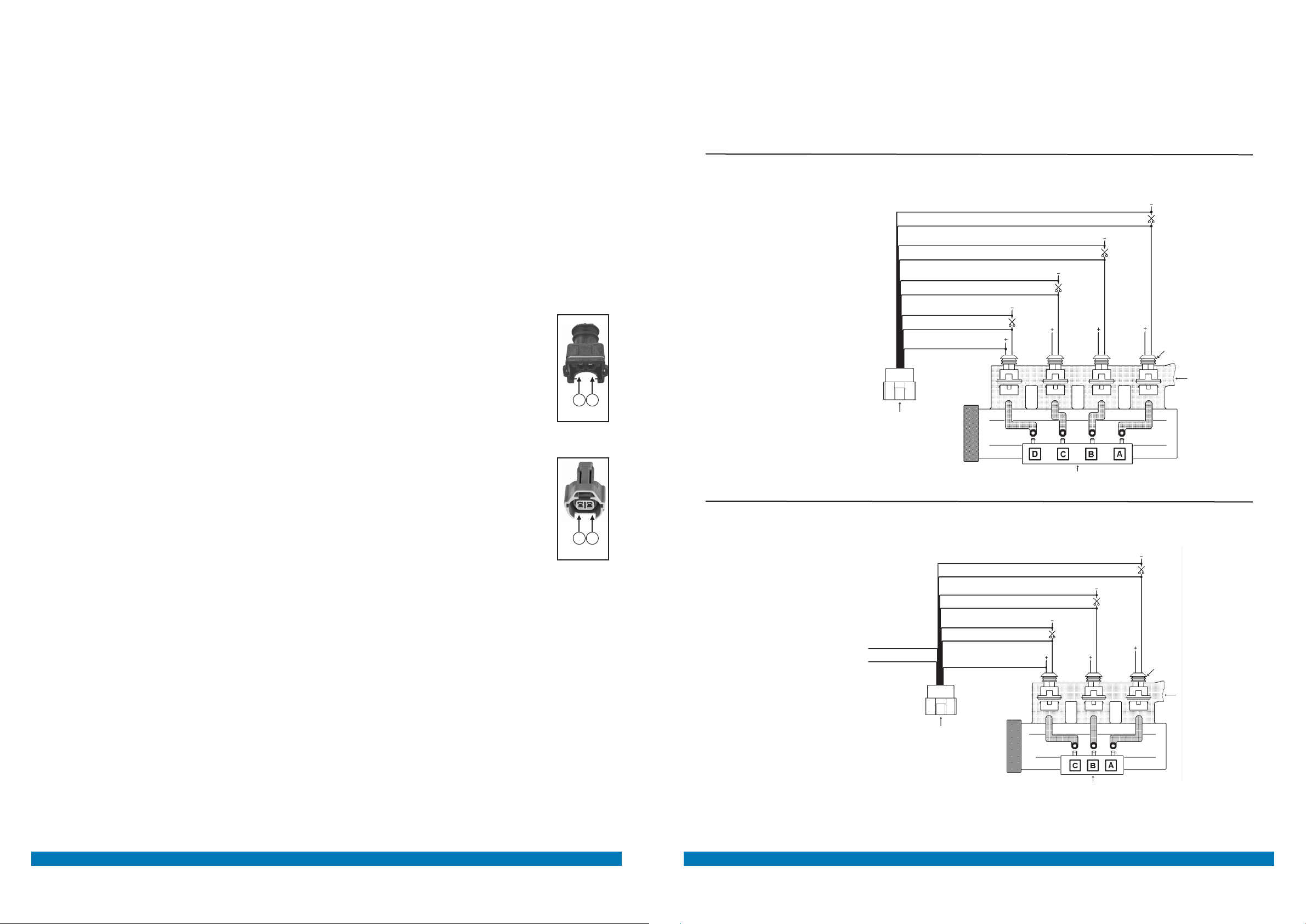
DESCRIZIONE DEI CABLAGGI STACCA INIETTORI COLLEGAMENTO CABLAGGIO STACCA INIETTORI uNIVERSALE
INIETTORI BENZINA
COLLETTORI
D’ASPIRAZIONE
RAIL INIETTORI GAS
3 CILINDRI
BLU-NERO
BLU
ROSSO-NERO
ROSSO
VERDE-NERO
VERDE
GIALLO-NERO
GIALLO
BIANCO-ROSSO
CONNETTORE
DEL CABLAGGIO
STACCA INIETTORI
NON
COLLEGARE
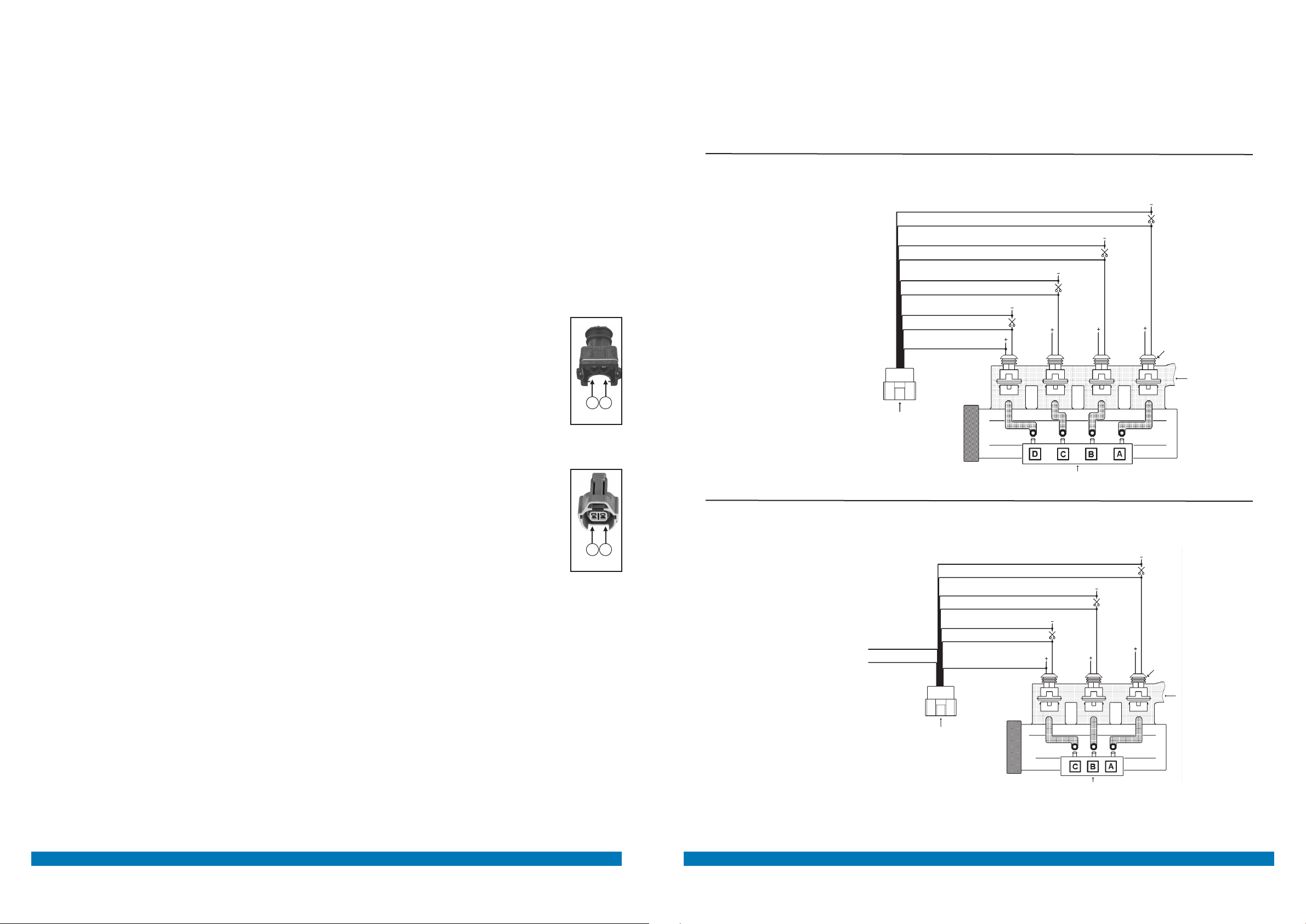
SA144U
Il cablaggio Cod. SA144U ha tutti i li liberi senza connettori, questo cablaggio va utilizzato su quelle
autovetture dove non è possibile installare gli altri cablaggi, o dove non sia possibile accedere ai connettori
originali degli iniettori.
Per installare questo cablaggio occorre tagliare i li negativi degli iniettori benzina, seguendo l’ordine riportato
in gura.
È molto importante il verso di collegamento, i li rigati NERI vanno verso la centralina d’iniezione benzina, gli
altri verso gli iniettori.
Il lo BIANCO-ROSSO va collegato a uno qualsiasi dei positivi iniettori.
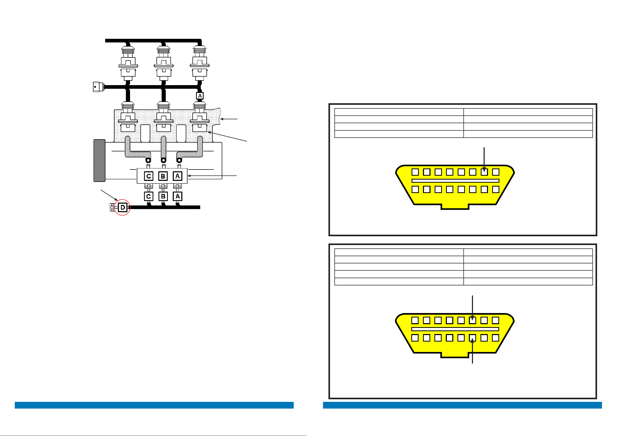
ATTENZIONE!
Rispettare la sequenza dei
collegamenti, i li BLU e
BLU-NERO devono
essere in corrispondenza
dell’iniettore gas marcato A,
gli altri di seguito come in
gura.
I FILI DA INTERROMPERE
SONO I NEGATIVI
INIETTORI.
ATTENZIONE!
Nel caso di collegamento su
di una vettura 3 cilindri i li
GIALLO e GIALLO-NERO
vanno lasciati
scollegati, vedi schema.
Schema di collegamento per vetture 3 cilindri
Schema di collegamento per vetture 4 cilindri
+12 VOLT SOTTO CHIAVE
INIETTORI BENZINA
COLLETTORI
D’ASPIRAZIONE
RAIL INIETTORI GAS
4 CILINDRI
CONNETTORE
DEL CABLAGGIO
STACCA INIETTORI
BLU-NERO
BLU
ROSSO-NERO
ROSSO
VERDE-NERO
VERDE
GIALLO-NERO
GIALLO
BIANCO-ROSSO
+12 VOLT SOTTO CHIAVE