Westward 31CE52 Service manual

Please read and save these instructions. Read through this owner’s manual carefully before using product. Protect
yourself and others by observing all safety information, warnings, and cautions. Failure to comply with instructions could
result in personal injury and/or damage to product or property. Please retain instructions for future reference.
ROLLING CABINET
Operating Instructions and Parts Manual 31CE52
MGC100002
Printed in China
09/14
Description
The Westward rolling cabinet has a durable black finish and strong load capacity. The cabinet is equipped with full
extension ball bearing slides, ensuring smooth functionality of all drawers. Each drawer can hold up to 66 lbs(30kg).
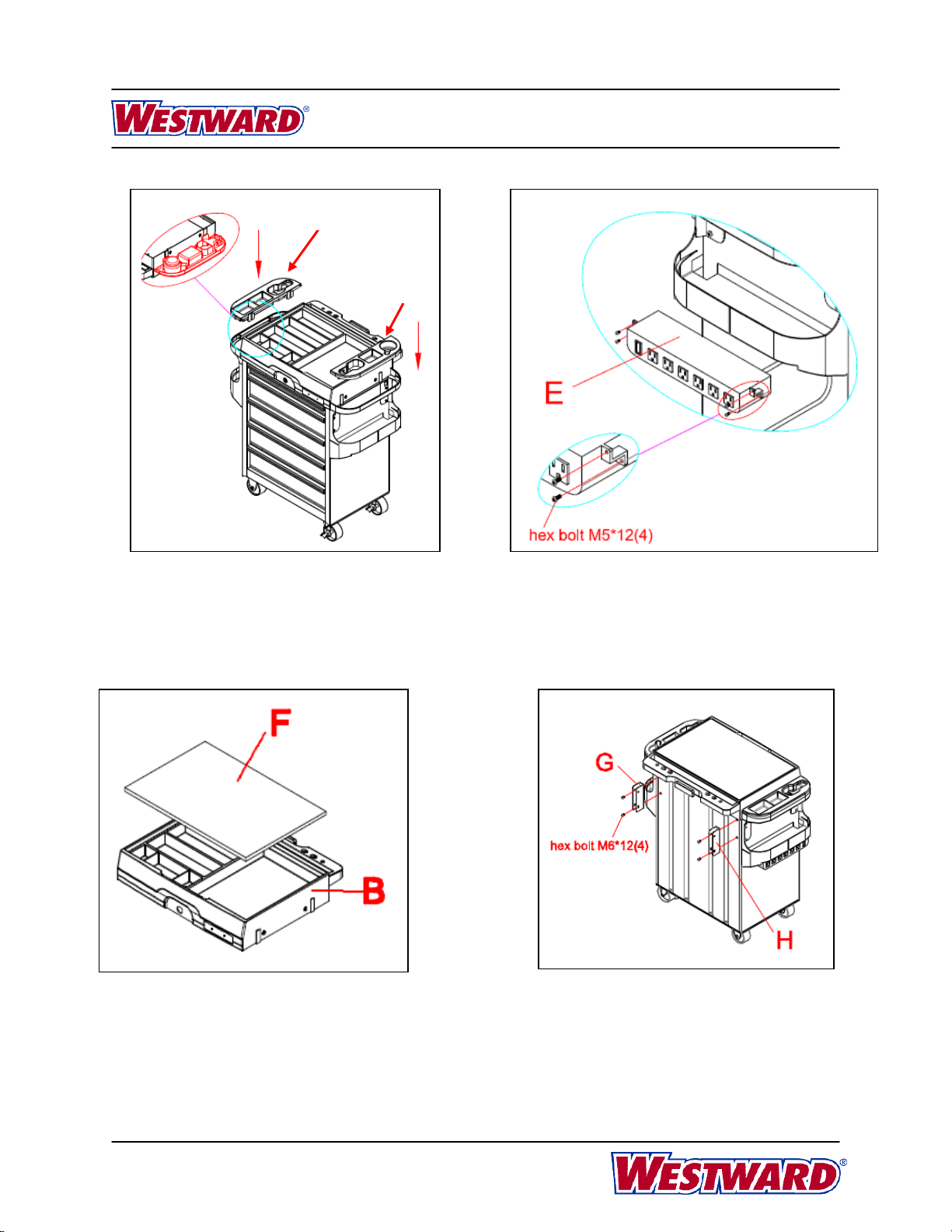
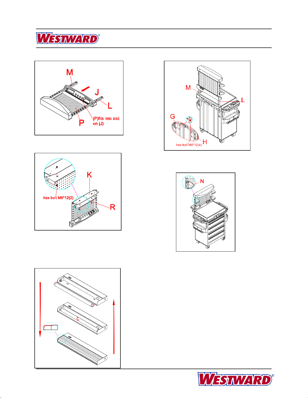
Also outfit with multi-functional tray , 20mm MDF work top covering with galvanized sheet, peforated pegboard for
holding the parts, character the light fixture, power tap for convenient work. The cabinet is ideal for mechanics,
craftsmen, repairmen and garage owners interested in storing and organizing tools and parts.
Unpacking
When unpacking, please ensure the unit is
upright. Do not use any sharp objects to open the packaging.
After unpacking unit, inspect carefully for any damage
that may have occurred during transit. Check for loose,
missing, or damaged parts. Any shipping damage claim
must be filed with the carrier.
Specifications and Dimensions
31CE524’’×2’’PP CASTERS 526.69”(678MM) 18.07”(459MM) 33.82”(859MM)
General Safety Information
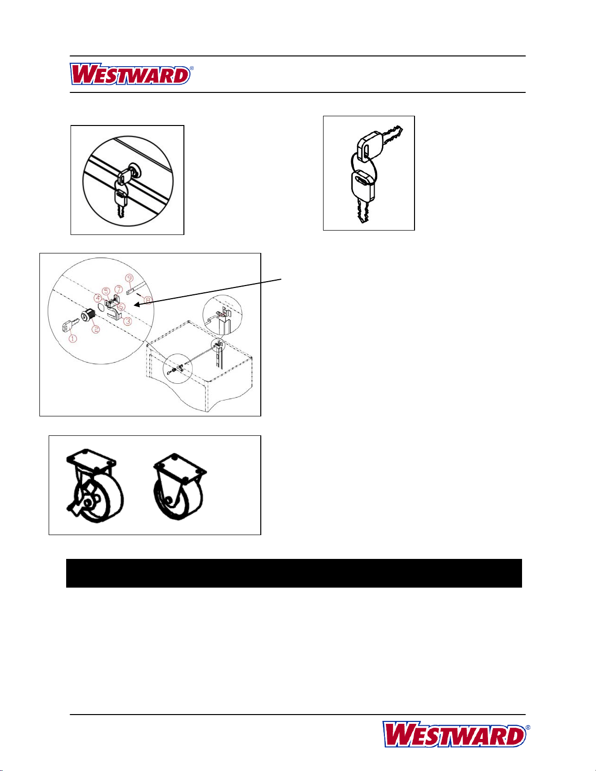
Ensure the drawers are closed and locked completely before moving the cabinet.
Handle and swivel casters must be attached on the same side of the product.
Keep the product on level surfaces. The product may become unstable and tip if stored or moved on an un-
level surface, which may cause personal injury or product damage.
Do not alter the product in any manner. Do not step or climb on the cabinet.
Do not open more than one drawer at the same time. The cabinet may become unstable and tip.
Please ensure the cabinet is locked prior to moving.
Please ensure the same power during the connection between the extension and the original cord of the power tap.
Maintenance
Lubricate the lock with graphite annually. Lubricate the ball bearing slides with grease twice annually. The casters do
not require lubrication.
Steel Body Dimensions (Inches)
Model Casters No. of Drawers Width Depth Height

2
31CE52
Westward Operating Instructions and Parts Manual
Rolling Cabinet
Assembly
When assembling the cabinet, please start from top to bottom.
Hardware Included
CASTER ASSEMBLY
1. Place the cabinet wheels up on a flat
surface. Protect the paint by placing the
packaging down first.
2. Insert the bolt into the spring washer, then
the washer. Attach the caster to the mounting
plate. Mount both swivel casters on the same
side of the cabinet as the side handle.
3. Tighten all bolts by hand until the cart is
assembled. Then, tighten the bolts using a
wrench until you feel resistance. Do not over
tighten.

3
31CE52
Westward Operating Instructions and Parts Manual
Rolling Cabinet
1.Attach saddles bags (A).
2.Insert (4) tabs on (A) into slot on both
sides of the unit and slide down into
place.
3. Install PP top tray (B) on unit using
(4)M6*20 hex bolt.
Note: Line up tabs on both sides of PP top
tray (B) with slots on the cabinet.
NOTE: This unit was shipped with the plastic top on the unit, remove the top from
the unit and all parts from the drawers before proceeding with the assembly steps.
WARNING
CABINET EXPLODED VIEW

4
31CE52
Westward Operating Instructions and Parts Manual
Rolling Cabinet
D
C
4.Install (C) and (D) on both sides
through the slides on (B).
Note: (C) and (D) can be attached to
either side of the unit.
5. Note: (E) can be attached to either side of the
unit. Left side mounting shown.
Attach (E) to saddle bag using (4) M5*12 hex bolt
as shown.
Remark: There is one 1.6M length extension
cord for the six out-let power tap.
6. Install (F) MDF top to (B) PP tray.
7.Attach (G) and (H) using (4)M6*12 hex bolt. Parts
must slide between saddle bag and cabinet on the
sides. Wrench tighten (Don’t over tighten).

5
31CE52
Westward Operating Instructions and Parts Manual
Rolling Cabinet
8. Attach (I) to (J) using (4) M5*12 hex
bolt. Cord must be fed through the back
of (J) for proper fit.
9. Assemble (K),(L) and (M) using(4) M6*12 hex
bolt.. Wrench tighten (Don’t over tighten).
10. Attach (O) to (K) using (5) M4*10 hex bolt.
Wrench tighten (Don’t over tighten).
11. Slide (P) into grooves on (L) and (M), so it
fits into the grooves on (O).

6
31CE52
Westward Operating Instructions and Parts Manual
Rolling Cabinet
12.Slide (J) onto (L) and (M), so (P) fits
into slot on (J).
13. Align slots in (L) and (M) with holes in (G)
and (H), and attach with (4) M6*12 hex bolt.
14.Attach (2)M6*12 hex bolt to (K). Leave enough gap
to allow (R) to hang from the hex bolt.
Note: Plastic Hood not shown for clarify.
Attach (R) to the hex bolt. Slide (R) over to hook into
place.
15. Attach (N) (4) where desired.
1. To reinstall the light bulb, line up the pins of
the bulb with the holes on the light fixture, roll it
inwards firstly, then to secure it in place.
2. To reinstall the lampshade, push it inwards
slowly, then to secure it in place.
Handle them in the opposite direction when
uninstall the bulb and lampshade.

7
31CE52
Westward Operating Instructions and Parts Manual
Rolling Cabinet
Warranty
LIMITED ONE-YEAR WARRANTY
Should this product fail to perform satisfactorily due to a defect or poor workmanship within ONE YEAR from the date of
purchase, return it to the place of purchase and it will be replaced free of charge. Incidental or consequential damages are
excluded from this warranty.
For Repair Parts, call 1-800-323-0620
24 hours a day – 365 days a year
Repair Parts Illustration for Model(s) 31CE52
DRAWER OPERATION
To remove the drawer:
1. Empty the drawer, fully extend the drawer,
release the retaining clip by pushing the lever up
on one side and down on the other side
simultaneously.
2. Then pull the drawer out.
To reinstall drawers:
To reinstall drawers, place on slide channels
and slide drawer in completely.

8
31CE52
Westward Operating Instructions and Parts Manual
Rolling Cabinet
Repair Parts
Repair Parts List
1. Lock and key set TTLK001G 1
2. Keys MGC01XXX 2
(Please refer to the number on the key/lock for the last three digits.)
3. Fixed Caster and Swivel caster with brake TT42PPG 1
(For 31CE51,31CE52, 31CE53,31CE55)
Manufactured for Grainger International, Inc.
100 Grainger Pkwy., Lake Forest IL 60045 U.S.A.
Keys, parts number:
MGC01XXX . Please
refer to the number on
the key/lock for the
last three digits.
Lock and key
set, parts
number:
TTLK001G
Fixed Caster and Swivel caster with brake, parts
number: TT42PPG, for 31CE51, 31CE52,
31CE53, 31CE55
Reference
Number Description Part Number Qty.
To remove lock and key set:
1. Remove 2 or 3 drawers first from the top down.
2. Remove spring clip ③using hand tool,eg: pinchers.
3. Pull out the whole central lock including key ①, lock ②, U
Shape④, flat washer ⑤, spring washer ⑥, bolts ⑦, clip
⑧, central locking bar ⑨.
4. Take apart bolts ⑦using cross screwdriver, then remove
the discarded key ①, lock ②.
To reinstall lock and key set:
1. Assembly key ①,lock ②,U Shape④,flat washer ⑤,
spring washer ⑥,bolts ⑦,clip ⑧,central locking bar ⑨in
sequence, insert the whole central lock through the front
hole till up to the hole of locking bar at the back of the
cabinet.
2. Insert spring clip ③on the lock.
3. Tighten all bolts.
Table of contents
Other Westward Indoor Furnishing manuals