-3 - - 4 -
EI53C9.25-2048-SA5N2TH SIN-COS Photoelectric Encoder User GuideEI53C9.25-2048-SA5N2TH SIN-COS Photoelectric Encoder User Guide
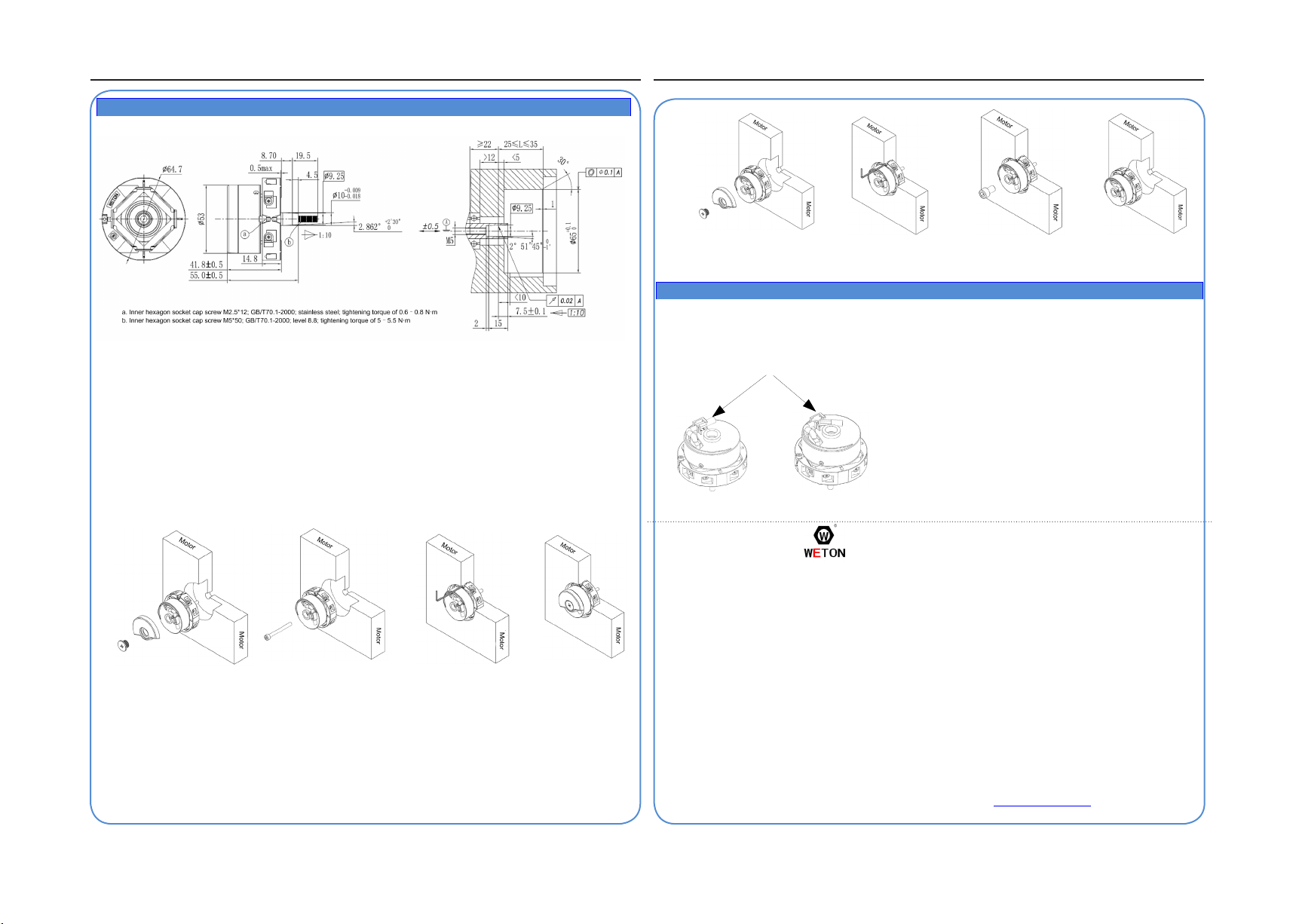
3. Installation Guide
■Installation Diagram
Figure 3-1 Installation dimension Figure 3-2 Recommended traction machine dimensions for the encoder
■Installation and Uninstallation Description
☞Installation diagram
1)
Remove the front cover of the encoder. The conical shaft is displayed, as shown in Figure 3-3.
2)
Put the encoder into the location hole of the traction machine until the conical shaft is stuck. Put the M5*50 inner
hexagon screw through the center hole of the conical shaft, and tighten the screw into the hole of the traction machine.
The required tightening torque is 5 N·m to 5.5 N·m. Ensure that the conical shaft and hole are concentric, as shown in
Figure 3-4.
3)
Tighten the screw clockwise to x the expander. The required tightening torque is 0.6 N·m to 0.8 N·m. Ensure that the
expander is tightened properly, as shown in Figure 3-5.
4) Install the front cover of the encoder. The installation is complete, as shown in Figure 3-6.
Figure 3-3 Figure 3-4 Figure 3-5 Figure 3-6
☞Uninstallation diagram
1) Remove the front cover of the encoder. The conical shaft is displayed, as shown in Figure 3-7.
2) Unscrew the screw counterclockwise to loosen the expander, as shown in Figure 3-8.
3)
Unscrew the M5*50 screw counterclockwise for two to three turns. Then, screw the M10*20 screw clockwise into the
center hole of the conical shaft to jack up the M5*50 screw until the conical shaft leaves the hole, as shown in Figure 3-9.
4) Back off the M10*20 screw and the M5*50 screw in sequence. Then, take off the encoder, as shown in Figure 3-10.
Figure 3-7 Figure 3-8 Figure 3-9 Figure 3-10
4. Cable Shielding
1) Connect the shielded cable to the ground through the housing of the encoder.
2) Before removing the shielded cable from the traction machine, remove the housing cover, and isolate the
grounded shielding ring and the encoder housing, as shown in Figure 4-1.
Figure 4-1 Shielding cable socket diagram
Warranty Agreement
1)
The warranty period of the product is 12 months from the date of delivery. During the warranty period,
if the product fails or is damaged under the condition of normal use by following the instructions, Weton
will be responsible for free maintenance or replacement.
2) Within the warranty period, maintenance will be charged for the damages due to the following causes:
A. Improper use or repair/modication without prior permission
B. Fire, ood, abnormal voltage, other disasters, and secondary disasters
C. Hardware damage caused by dropping or transportation after procurement
D. Failure to operate the encoder by observing the User Manual provided by Weton
E. Trouble out of the equipment (for example, external device)
3) In case of fault or damage, please ll in the Product Warranty Card with correct and detailed information.
4) The maintenance fee is charged according to the latest Price List of Weton.
5) Please keep this Warranty Card carefully for future maintenance needs.
6) If you have any further issues, contact Weton or our agencies.
7) This agreement shall be interpreted by Weton.
Weton Optoelectronic Co., Ltd.
Address: No.456, Zhongheng Road, High Technology Development Zone, Changchun, China (130012)
Tel: +86-431-81050600 81050611 Website: http://www.weton.net
☞Safety Instructions
◆If the stall occurs, the encoder may be installed improperly. Remove the
encoder and install it again.
◆Connect cables by strictly following the wiring list to access only correct
signals, avoiding encoder failures.
◆When pushing the encoder into the hole of the traction machine, ensure
that the conical shaft and hole are concentric.
◆The encoder is a precise optical component. Therefore, avoid knock,
beat, and collision during installation and uninstallation.
◆To avoid interference, do not connect the encoder cables in the
same trunking with the power cable. The shielded cable must be well
grounded. If the grounding is unreliable onsite, take out the shield short-
circuiter.


