WFCO WF-9500-AD-MBA Series User manual

OPERATOR’S MANUAL
WF-9500-AD-MBA SERIES
WF-9540-AD-MBA | WF-9560-AD-MBA | WF-9580-AD-MBA
( The Power Center model number is located on the front panel label next to the breakers)
ARTERRA DISTRIBUTION
(877) 294-8997
wfcoelectronics.com
WARRANTY
Fax (574) 294-8698
Distributed by Arterra in the U.S.A. and Canada

2
SAFETY INFORMATION ...................................................................................................... 3
GENERAL INFORMATION
Automatic Cooling Fan ....................................................................................................... 3
Over-Temperature Protection .............................................................................................. 3
Electronic Current Limiting ................................................................................................... 4
Short Circuit Protection ........................................................................................................ 4
CIRCUIT PROTECTION
Reverse Battery Protection ................................................................................................... 4
OPERATIONAL FEATURES
Auto Detect ............................................................................................................................ 5
Three Stage Smart Charging ................................................................................................ 5
Two Stage Smart Charging ................................................................................................... 6
TROUBLESHOOTING INSTRUCTIONS
Converter Output Voltage .................................................................................................... 8
Reverse Polarity Fuses ........................................................................................................... 8
Troubleshooting Flow Chart ................................................................................................. 9
Replacing the MBA ................................................................................................................ 9
GENERAL COMPLIANCE INFORMATION
Agency Listings .................................................................................................................... 11
INSTALLATION INSTRUCTIONS
Mounting the MBA .............................................................................................................. 11
WARRANTY INFORMATION............................................................................................... 12
SPECIFICATIONS.................................................................................................................. 13
TABLE OF CONTENTS

3
GENERAL INFORMATION
WF-9500-AD-MBA Series Main Board Assembly Safety Features
AUTOMATIC COOLING FAN
The cooling fan in the WF-9500-AD Series Power Center is incremental and is controlled by the
current drawn out of the converter to the applied load. The on-board microprocessor increases
fan speed as the total load increases and decreases fan speed as the load decreases. Unlike
traditional temperature-controlled fans, the load-controlled fan provides better component
cooling by avoiding temperature spikes which can lead to premature component failure.
OVER-TEMPERATURE PROTECTION
If the internal temperature of the converter exceeds a critical point, it will shut down. This
protects the unit from excessive heat that may damage sensitive components. The unit will
restart once the temperature inside has dropped.

4
ELECTRONIC CURRENT LIMITING
In the event that the output current exceeds the maximum rating for the WF-9500-AD Series
Power Center converter, the output current will remain constant but the output voltage will begin
to drop. If this occurs, the unit will recover once loads are reduced.
SHORT-CIRCUIT PROTECTION
Should a short circuit occur in the RV, the WF-9500-AD Series Power Center converter will drop
the voltage output to zero volts. If the short-circuit condition is removed and no other fault
conditions are detected, the converter will resume normal operation. However, short-circuit
conditions are dangerous, and an RV will require inspection by a qualied service technician.
CIRCUIT PROTECTION
CIRCUIT PROTECTION
WF-9500-AD-MBA Series Main Board Assembly Fuses and Breakers
REVERSE BATTERY PROTECTION
The WF-9500-AD-MBA Series Main Board Assembly will charge the 12-volt House battery if
installed. A battery DOES NOT have to be installed for WF-9500-AD-MBA Series Main Board
Assembly to operate. When a battery is installed, two reverse polarity fuses protect the MBA
circuitry. The fuses are located along the left-center edge of the DC fuse board below the VCC+
lug. Refer to Figure 1 on page 5. This feature prevents permanent damage to the MBA from a
battery connected into the circuit backwards. In addition to protecting the MBA, the reverse
polarity fuses are the main connection between the MBA and the DC fuse board.
The fuse values and quantity vary depending on which WF-9500-AD-MBA Series Main Board
Assembly you have. Refer to the table below.
• WF-9540-AD-MBA – 25A (2)
• WF-9560-AD-MBA – 35A (2)
• WF-9580-AD-MBA – 30A (3)
The circuit fuses and the Reverse Battery Protection fuses should be replaced with ATC or ATO
automotive type fuses such as:
• Littelfuse type 257
• Bussmann type ATC

5
AUTO DETECT
This product includes the exclusive “Auto-detect” feature for the charging of batteries. With
this new technology, the power converter will evaluate the charging cycle of a battery, determine
the type of battery being used, and then choose the appropriate charging program(prole) to
provide for the best performance and maintenance of that battery.
Because of the differences of Lead Acid, AGM and Lithium type batteries, a system that
provides a charge to the battery or batteries must be able to accommodate the different
charging requirements. With the use of the “Auto-detect” product, the charging requirement
is able to be “detected” and is then automatically set for the type of battery being used. For
standard Lead Acid and AGM batteries, WFCO power converters still use the Three-Stage Smart
Charging to effectively maximize battery life by monitoring through the different phases of the
charge cycle. On the other hand, Lithium batteries will prefer the use of only two stages when
charging, and therefore the power converter will charge using the WFCO Two-Stage Smart
Charging system.
LEAD ACID & AGM THREE-STAGE SMART CHARGING
In order to maximize battery life for lead acid and AGM, it is best to charge batteries
slowly, keep them topped off with a trickle-charge when the RV is not being used. The 3-Stage
“smart” charger continuously measures the battery voltage output and regulates the amount of
charge using three modes of operation; Absorption, Bulk and Float modes.
All WFCO power converters are automatic three-stage switching power supplies. The converter
senses which mode it needs to be in by checking the RV system voltage.
ABSORPTION MODE
The converter normally provides a constant target output voltage of 13.6 VDC (nominal) to
power all the branch circuits. However, it is current limited, and if the output (load) current
reaches its maximum, the output voltage will drop as necessary to hold the converter’s maximum
output current level (the Amperage rating) without exceeding it.
Figure 1
DC FUSE BOARD
OPERATIONAL FEATURES

6
NOTE: for a detailed explanation of the charging modes, please refer to our publication Theory
of Operation, document #AD-TD-0001-0.
BULK MODE
If the output current reaches its maximum (normally caused by a discharged battery), this will
cause the converter to go into Bulk Mode, which means the target output voltage will change
to 14.4 VDC and a timer will start. Although the converter is outputting 14.4 VDC, you will not
be able to read that on a voltmeter due to the voltage-current relationship. From the paragraph
above, as load current increases, output voltage decreases. The actual output voltage will not
rise until the load current is reduced, which happens naturally as the battery charges or if 12 VDC
appliances are turned off.
Bulk Mode will be maintained until the current draw drops to approximately ve Amps, or until
the timer reaches four hours (whichever happens rst). Then the target output voltage is changed
back to 13.6 VDC for Absorption Mode. Lights that are powered from the output may change
brightness slightly at that time.
FLOAT MODE
The third mode of charging is what is called the “oat” charge. This mode is designed to
provide a “trickle charge” to the battery after the system observes no signicant variations in
current draw over a long period of time. When in “oat” mode, the voltage will reduce from
13.6V to 13.2V and supply the “trickle charge” which helps to preserve the life of the battery
while keeping it charged and r
eady for use. A change in DC current will cause the converter to exit the mode and return to the
Absorption mode and then to Bulk mode if required.
Note: For a detailed explanation of the charging modes, please refer to our publication “Theory
of Operation”, document #AD-TD-0001-0.
LITHIUM TWO-STAGE SMART CHARGING
The two-stage “smart” charger continuously measures the battery voltage output and regulates
the amount of charge using two modes of operation: Bulk and Absorption mode.
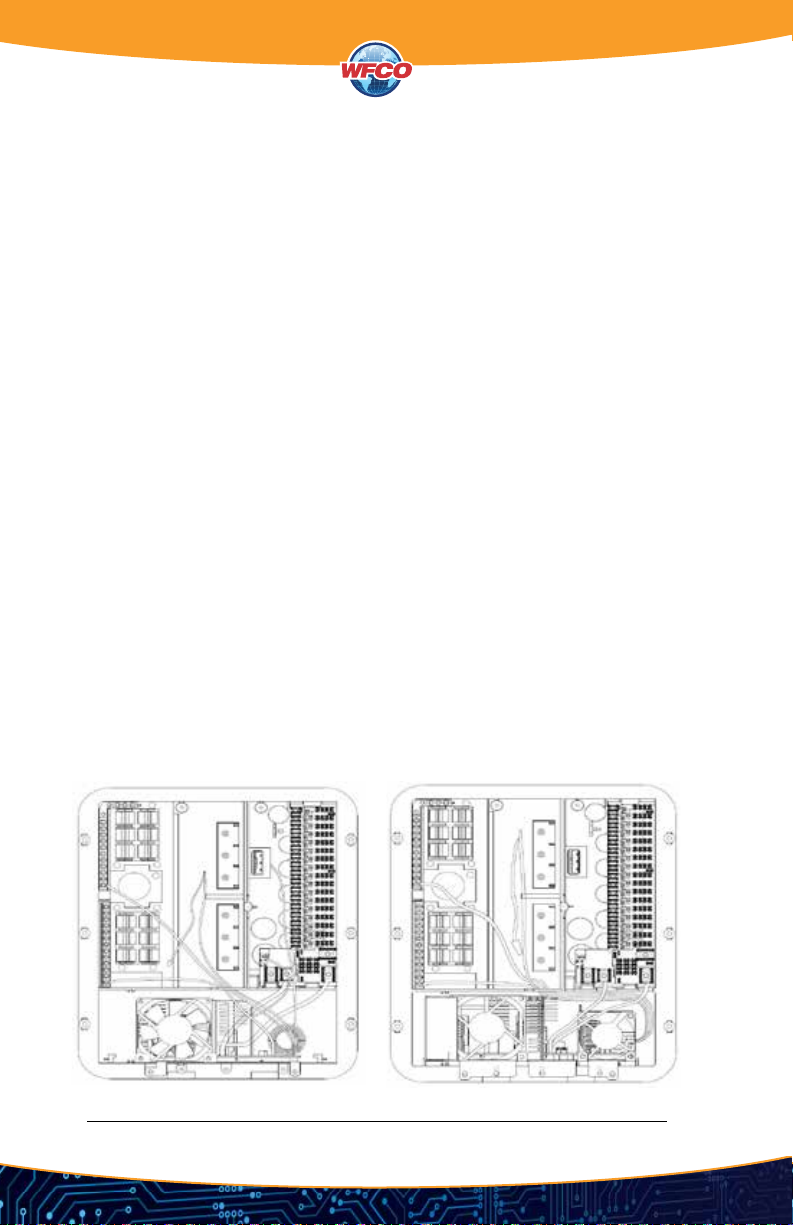
2-STAGE CONVERTER VOLTAGE OUTPUT MODES
Understanding output voltages of a two-stage converter.
Figure 2

7
BULK MODE
This mode is designed with two purposes in mind. First, to quickly restore the energy back into
the battery. Second, to ensure the lithium cells inside the battery remain balanced. This is
accomplished by boosting the output voltage to 14.6 VDC and allowing the maximum current to
ow as required by the loads.
The bulk mode stage could last anywhere from one to four hours based on the battery and load
current which is being used. For a full battery, the bulk stage has a minimum time requirement of
one hour, which allows the lithium cells inside the battery the time required to “balance”.
For an empty battery, the bulk stage has a maximum time requirement of four hours. If your
application requires longer than four hours (such as a larger battery bank > 200 Ahr), a simple
cycling of power will reset the timers.
As the energy is restored into the battery, the DC system voltage will climb and the current from
the converter will decrease. If the total amperage draw from the converter reaches a preset point
(within the one to four hour timer), the converter is designed to drop out of bulk mode.
ABSORPTION MODE
This mode is designed with one purpose in mind. This purpose is to provide a safe operating
voltage for all loads in the RV. This is accomplished by reducing (from bulk mode) the output
voltage to 13.6 VDC and remaining at this voltage until the power is cycled to the converter.
The absorption mode stage is the default or normal mode of operation, which has no timer
associated with it. In this mode an output of 13.6 VDC is provided to the DC circuits in the RV.
This voltage has a long-term history as the acceptable voltage for all loads in the RV, and should
not place undue stress (nor reduce the longevity) of the lights and appliances in the RV. This is not
to say that all loads will have an issue with a constant higher voltage; however, some loads may
have an issue. Please refer to the individual manufacturer’s specications for acceptable
operating voltage range of the connected load.
Figure 3

8
Refer to the Troubleshooting Guide for the WF-9500-AD-MBA Series Main Board Assembly
(Figure 4) below.
CHECKING CONVERTER OUTPUT VOLTAGE
Before checking the WF-9500-AD-MBA Series Main Board Assembly output voltage, disconnect
the battery cables at the battery. Make sure the converter is plugged into an AC source (105-130
Volts). Check the converter output voltage at the battery with a voltmeter. Place the meter probes
on the disconnected battery cables; place the Positive (red) meter probe on the + Positive
battery wire and place the Negative (black) meter probe on the - Negative wire on the battery
cable. Be sure you have good connections at the cables. If the voltage reads 13.6-14.6V, the
converter is functioning properly.
If the converter output voltage at the battery reads 0.0 VDC, or if the battery is not charging,
check for an open inline fuse in the battery wire circuit. One may have been installed by the RV
manufacturer. Also check for loose wiring connections.
CHECKING FOR REVERSE BATTERY HOOKUP (REVERSE POLARITY FUSES)
If there is no DC output coming from the WF-9500-AD-MBA Series Main Board Assembly
converter section, rst check the reverse polarity fuses on the fuse board. Then, visually inspect
the fuses for any breaks in the fuse element. If no breaks are found, use a continuity tester to
check for continuity. If the reverse polarity fuses are blown, it means the RV battery was
accidentally connected in reverse, either at the battery or at the converter. Investigate the
connections and reconnect the cables properly. Replace the fuse with the same type and
amperage rating as the original.
IMPORTANT: These fuses protect the converter from damage in the event that the RV battery is
accidentally connected in reverse. A reversed battery connection, even if for only a second, will
cause these fuses to blow.
TROUBLESHOOTING INSTRUCTIONS
Troubleshooting the WF-9500-AD-MBA Series Main Board Assembly

9
AC REVERSE POLARITY (AUDIBLE ALARM)
This power center is equipped with an AC REVERSE POLARITY PROTECTION feature. Should
the incoming AC neutral wire and lead wire be connected backwards at the power center, an
alarm located in the power center enclosure will sound. This alarm will continue to sound until
the AC wires are connected correctly.
If the above checks have been made but the converter output still reads 0.0 VDC, the converter is
not functioning properly. Contact the Arterra Distribution Power PROs at 1 (877) 294-8997.
Should it be determined that the WF-9500-AD-MBA Series Main Board Assembly needs to be
replaced, removal of the Main Board Assembly Is a simple process.
Figure 4

10
REPLACING THE CONVERTER SECTION (MBA)
DC WIRE REMOVAL
1. Drop door down and remove the door assembly by loosening the two screws in the upper left
and right corners of the door assembly. The screws are captive and will not fall out. Pull out at
the top of the door assembly to remove from case.
2. On the bottom left side of the fuse board nd the lug that is marked NEG and has a white wire
going to it. Loosen screw and remove wire.
3. On the bottom right side of the fuse board nd the lug that is marked VCC and has a red wire
going to it. Loosen screw and remove wire.
AC WIRE REMOVAL
CAUTION: MAKE SURE THE RV IS UNPLUGGED FROM ANY 110V POWER SOURCE
(SHORE CORD, GENERATOR, OR INVERTER).
4. Remove the converter black wire from the breaker. NOTE: This wire has a metal pin that is
inserted into the breaker with a pigtail wire added to it. If the pigtail wire is connected to
another wire, disconnect that wire from the pigtail.
5. Remove the converter white wire from the neutral bus bar.
6. Remove the converter green wire from the ground bus bar.
7. In the converter compartment, remove the two screws at the front of the MBA holding it in
place. Slide the MBA forward routing the wires through the slots in the case until you see the
majority of the MBA board. Disconnect the 3-pin connector on the MBA control board by
pulling it out of the socket. At this time, you can pull the MBA out of the case.
NOTE: When installing a replacement MBA, reverse the order of steps 1-7.
If the MBA is being returned under a warranty claim, follow the packaging instructions in your
warranty claim packet.
Figure 5

11
UL
The WF-9500-AD-MBA Series Main Board Assemblies are UL-Listed, and cUL-Listed (Canadian).
FCC COMPLIANCE CLASS B
NOTE: This equipment has been tested and found to comply with the limits for a Class B digital
device, pursuant to Part 15 of the FCC Rules. These limits are designed to provide reasonable
protection against harmful interference when the equipment is operated in a commercial
environment. This equipment generates, uses, and can radiate radio frequency energy, and if not
installed and used in accordance with the instruction manual, may cause harmful interference to
radio communications. Operation of this equipment in a residential area is likely to cause
harmful interference in which case the user will be required to correct the interference at his
own expense.
INSTALLATION INSTRUCTIONS
Installing the WF-9500-AD-MBA Series Main Board Assembly
MOUNTING THE CONVERTER SECTION (MBA)
Refer to Replacing the Converter Section (MBA) on page 10 for complete removal and
installation instructions.
GENERAL COMPLIANCE INFORMATION
Agency Listings

12
WFCO extends, to the original owner, a Two Year Limited Product Warranty. This warranty is in
effect from the date of original purchase for a period of two (2) years. This limited warranty is
extended specically for and is limited to Recreational Vehicle application and is only valid within
the continental United States, Alaska, Hawaii and the Provinces of Canada. WFCO warrants, to
the owner, that its products are free from defects in material and workmanship under normal
use and service based on its intended use and function. This warranty is limited to the repair or
replacement, at WFCO’s discretion, of any defective parts or defective assembly. Any implied
warranties of merchantability or tness for intended use are limited in duration unless applicable
State Law provides otherwise. You may have other rights as specied by each individual state.
EXCLUSIONS AND LIMITATIONS
The OEM warranty specically does not apply to the following:
• Any WFCO product that has been repaired or altered by an unauthorized person.
• Any damage caused by misuse, faulty installation, testing, negligence, accident or any WFCO
product installed in a commercial vehicle.
• Any WFCO product, whose serial number has been defaced, altered or removed.
• Any WFCO product, whose installation has not been in accordance to the WFCO
written instructions.
• Any consequential damages arising from the loss of use of the product including but not
limited to: inconvenience, loss of service, loss of revenue, loss or damage to personal property,
cost of all services performed in removing or replacing the WFCO product. Specications are
subject to change without notice or obligation.
• Any WFCO Electronics products sold through unauthorized Internet sources (Example: eBay)
will be excluded from all warranty coverage offered by Arterra Distribution / WFCO.
CONSUMER WARRANTY CLAIM PROCEDURE
Upon determination and validation by an authorized OEM dealer that a WFCO product has a
defect, a Return Goods Authorization (RGA) number will be required before the product can be
returned. The RGA number can be requested by completing the Warranty Information Fax Sheet
and appropriate Troubleshooting Form found at wfcoelectronics.com. Once these forms have
been completed, email the forms along with Proof of Purchase to warranty@wfcoelectronics.
com or fax the three documents to the Warranty Department at (574) 294-8698. After receipt of
the forms, an RGA number will be issued. This number shall appear on all correspondence with
warranty service. Upon validation of the warranty, WFCO shall replace the product with a like
product. The RGA number shall be placed on the outside of the carton used to return the
product for ease of identication.
Do not mark directly on the product. The product must be packaged properly to avoid further
product damage which could cause a non-warrantable condition.
CONSUMER LIMITED WARRANTY
for WFCO Electronic Products

13
WARRANTY ASSISTANCE
The consumer may contact the selling Dealer or OEM for warranty assistance. The consumer
may also contact Arterra Distribution, exclusive distributor to WFCO Products at: (574) 294-8997
or Fax (574) 294-8698.

ARTERRA DISTRIBUTION
(877) 294-8997
wfcoelectronics.com
WARRANTY
Fax (574) 294-8698
Distributed by Arterra in the U.S.A. and Canada
Power PROs Technical Support
(877) 294-8997
This manual suits for next models
3
Table of contents
Other WFCO Power Supply manuals

WFCO
WFCO WF-9900 Series User manual

WFCO
WFCO WF-8935MBA User manual

WFCO
WFCO WF-8500-AD-MBA Series User manual

WFCO
WFCO WF-8900-AD-MBA Series User manual

WFCO
WFCO WF-8500MBA Series User manual

WFCO
WFCO WF-89XX User manual

WFCO
WFCO WF-9500MBA Series User manual

WFCO
WFCO WF-8700 Series User manual

WFCO
WFCO WF-8735P User manual
Popular Power Supply manuals by other brands

StarTech.com
StarTech.com ATXPOW250PRO Instruction guide

Eurolux
Eurolux H187 quick start guide

Soundoff Signal
Soundoff Signal Quantum Q450 manual

Deif
Deif DPS-1 Installation and operation instructions

National Instruments
National Instruments FD-11601 CALIBRATION PROCEDURE

Elektro-Automatik
Elektro-Automatik PS 9040-40 2U operating guide