Fitting of Flow Switch and Filter
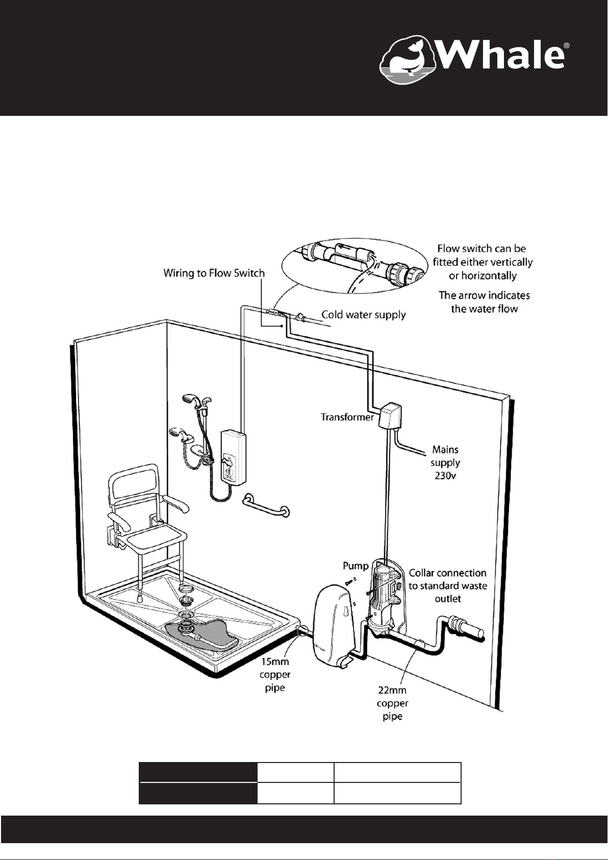
5.1 Install the flow switch and filter in the water
supply to the electric shower downstream of
any other connections to the water supply.
Ensure the flow switch is accessible
and mounted in a length of straight
unstressed pipe.
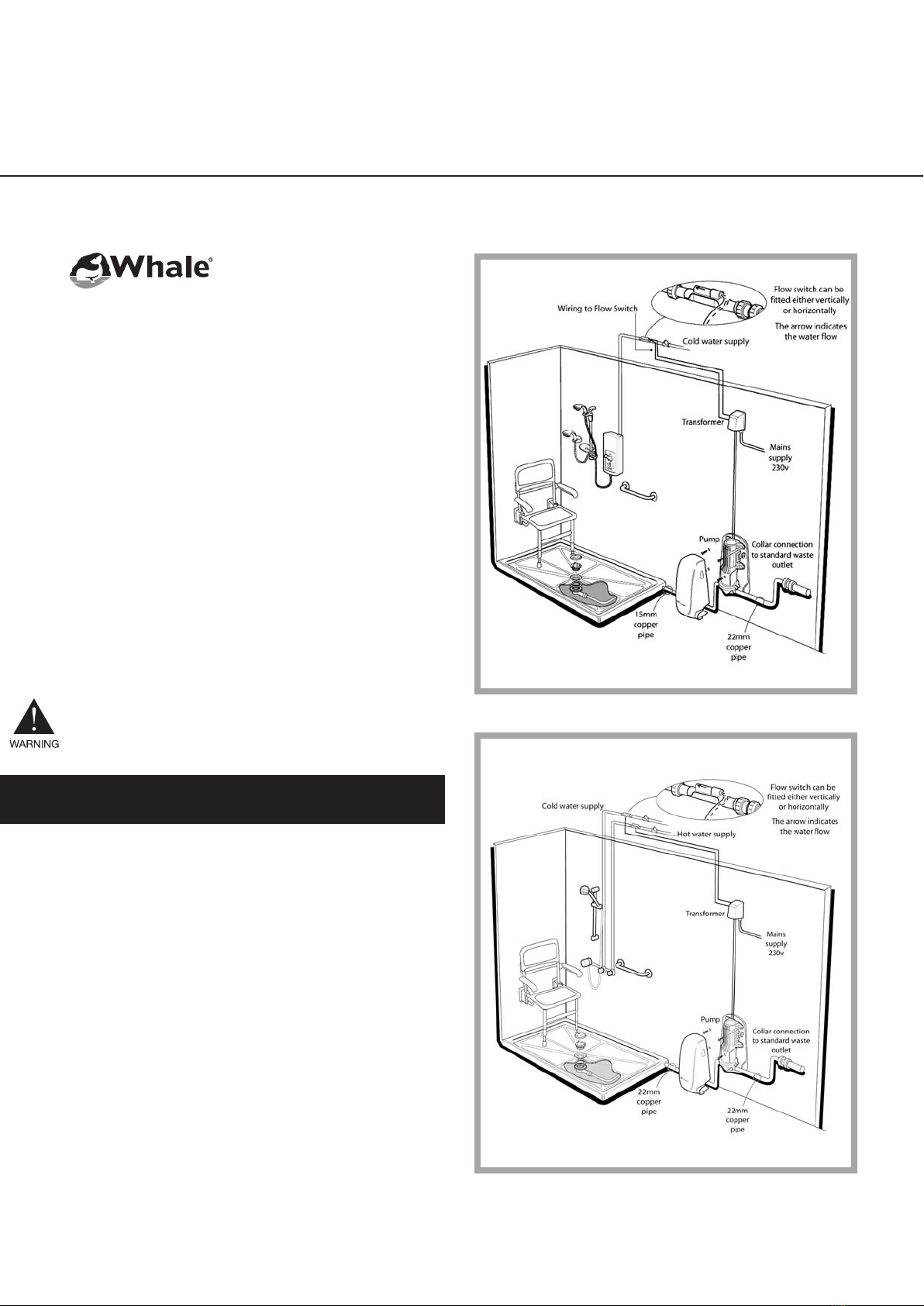
5.2 If a mixer valve is being used then an
additional flow switch and filter must be
installed in the hot water supply (Order Part
No. AK1570). The wires must be joined
together in parallel.
5.3 The flow switch is not polarity sensitive. Prior to
installation flush through the pipe to remove
any debris. Only use the push-fit fittings
supplied to connect the flow switch.
The arrow must be in the direction of water
flow. The flow switch may be mounted in any
orientation.
6.1 Electrical connections are as shown.
6.2 Mains supply to the transformer should be
made using a 5 amp fused spur.
6.3 Flow switch connections to the transformer
bell-wire are not polarity sensitive and can be
made using the electrical connector block
supplied.
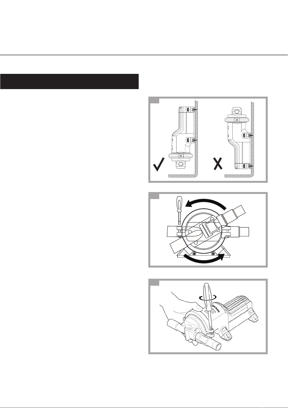
6.4 The transformer 24v RED and BLACK cable
supply to the pump should be terminated
using the crimp connectors supplied. Connect
to the pump RED and BLACK male crimps.
The polarity of the connection must be correct
for the pump to operate.
9
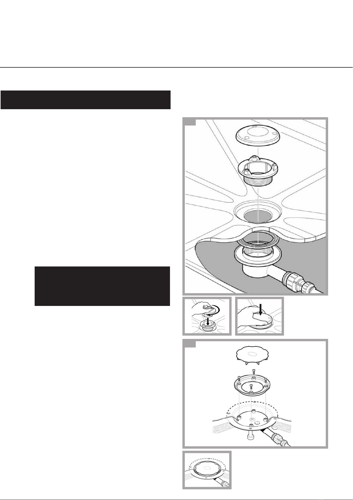
Flow Switch Connect
Electrical Connections 1.11
1.10
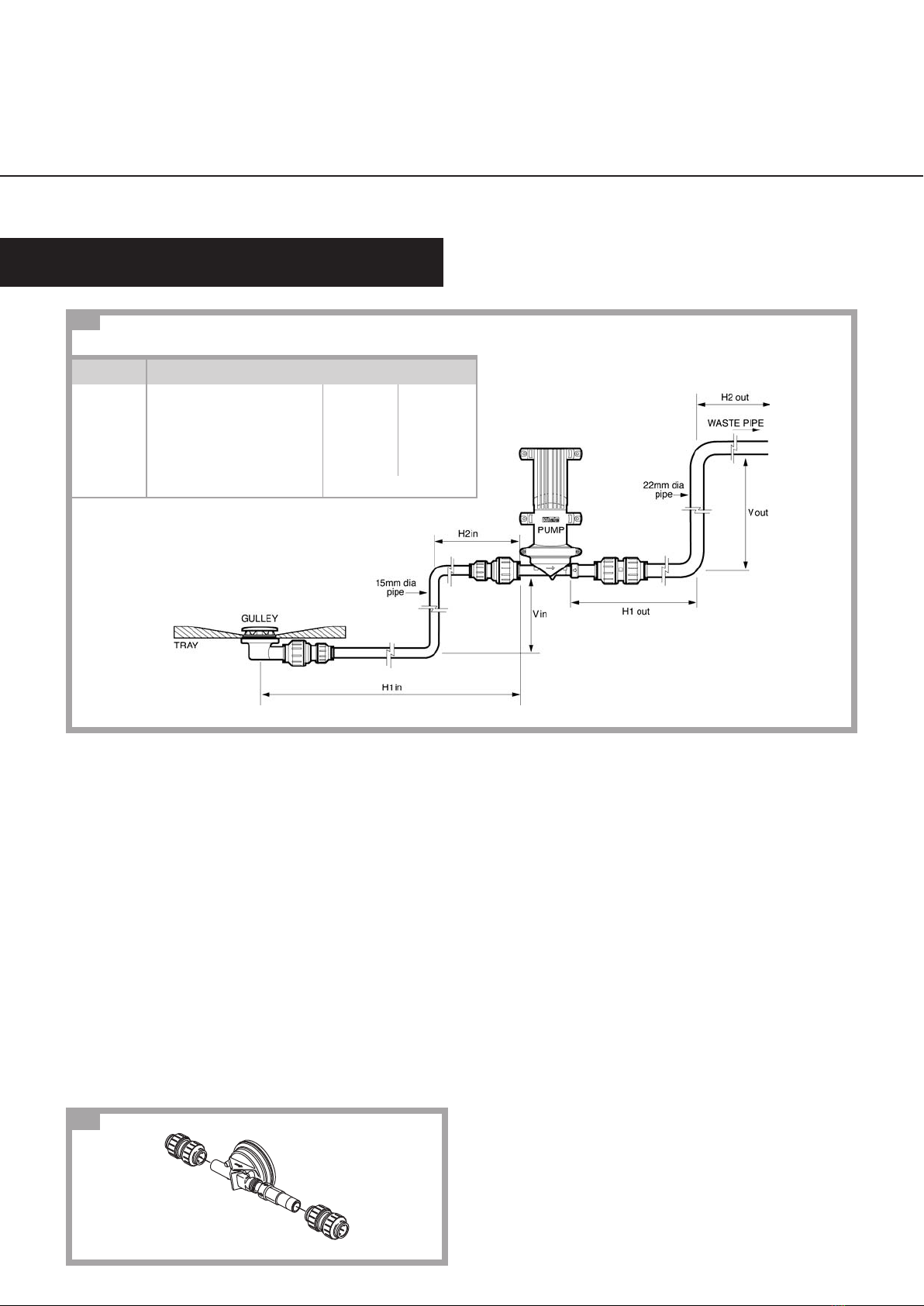
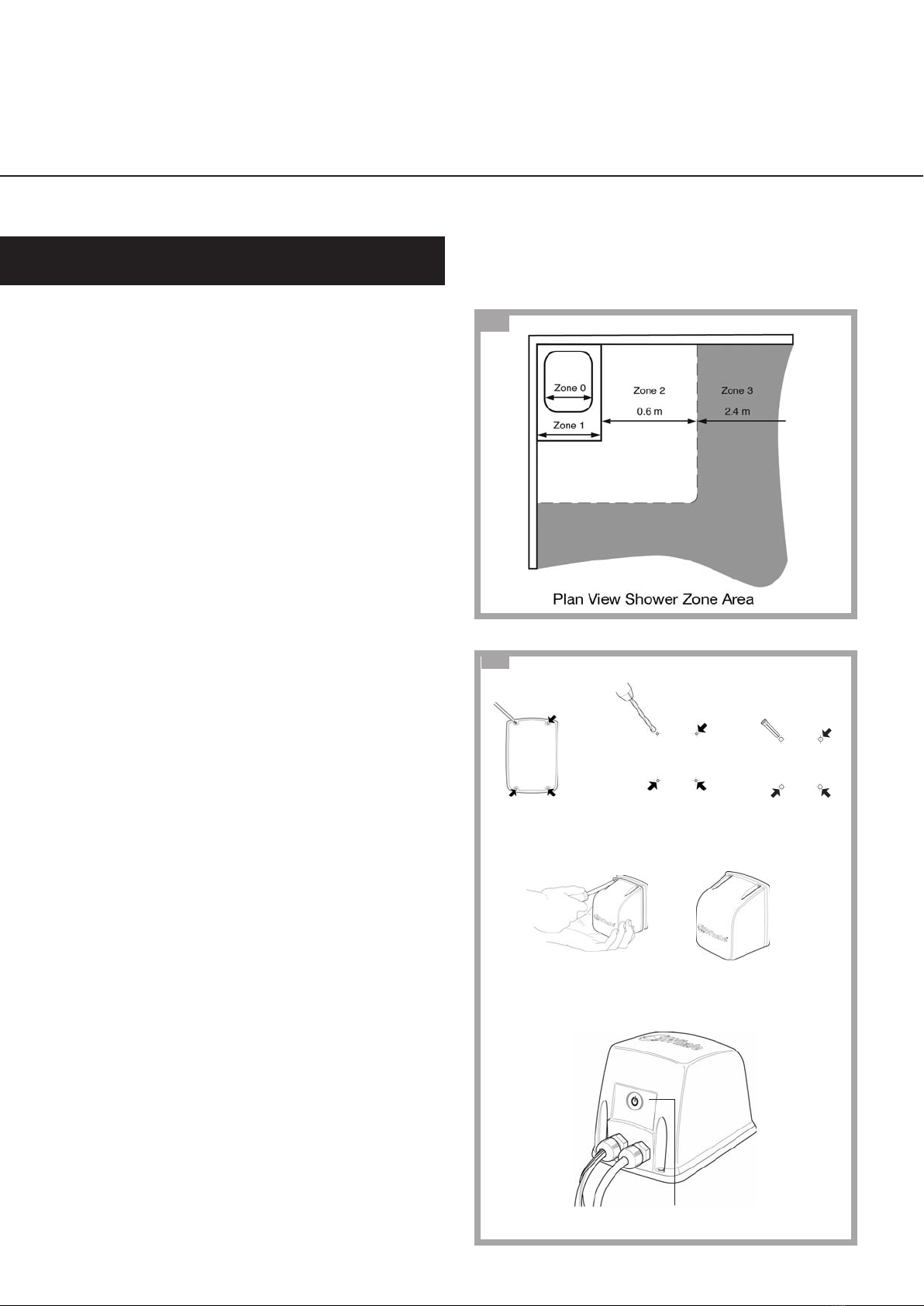
Flow Switch Operation
The flow switch is operated by a float with an
internal magnet housed in the copper pipe. In a
plastic housing on the outside of the pipe is a
magnetic reed switch. When the water flows
the float pushes against a spring. At above 1.5
litres/minute the magnet moves sufficiently to
activate the magnetic reed switch. When the
contacts are joined this signals the transformer
to switch power to the pump.
Note: The electric motor in the pump creates a strong
magnetic field which can hold the magnetic reed
switch open or closed. We recommend the flow
switch is not placed within 1 meter of the pump.