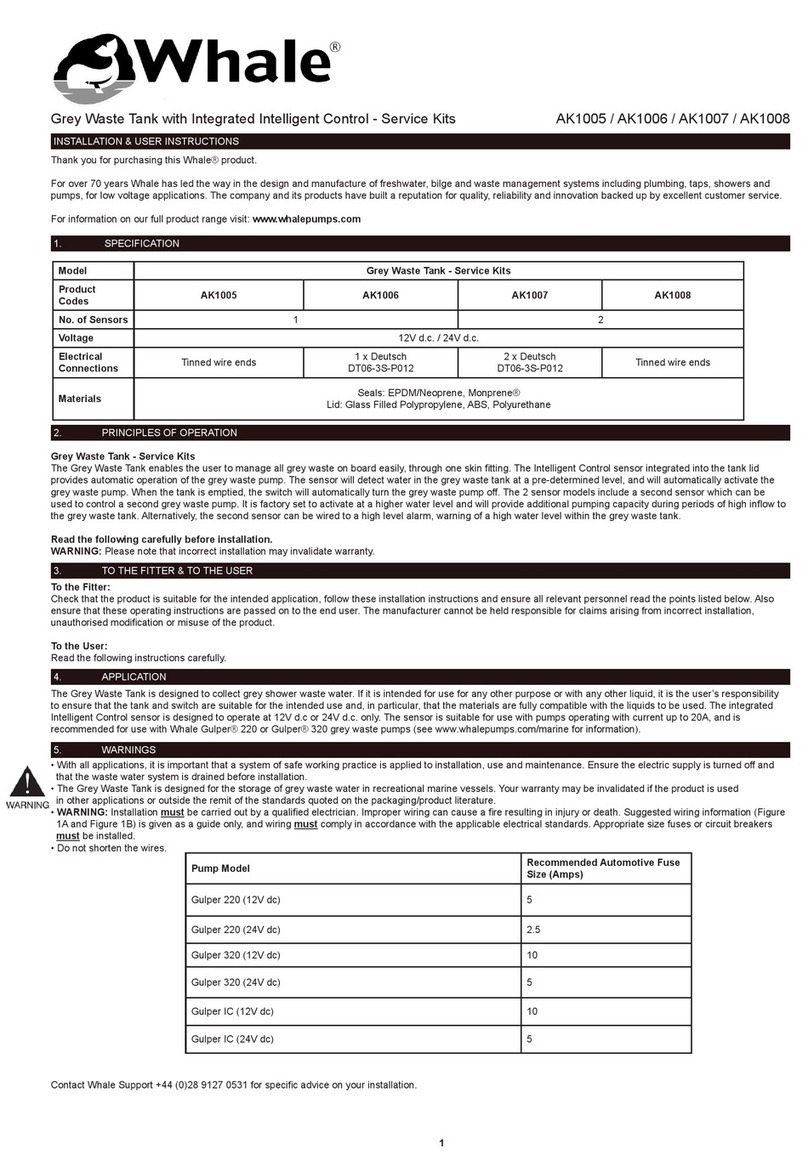
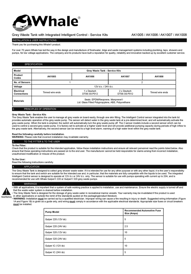
Whale Dry-Deck 20 SDP073R User manual

Dry-Deck 20
Installation Instructions
Model Number SDP073R Dry Deck 20
Installation guidelines for
Give booklet to customer after installation and demonstration of product use.
See rear cover for list of parts contained in the kit.

The Dry-Deck system is designed to work on
shower bases with an adequate fall to the gulley.
Where the fall is insufficient, the water will not refill
the gulley rapidly enough and so suction noise will
be increased. We recommend the use of a shower
former i.e. Impey Aqua Dec or equivalent. This
eliminates the risks of puddling or insufficient fall to
the gulley.
Forming a shower base by hand is a highly skilled
task and should be carried out by a trained
installer. Do not attempt this if you are unsure and
seek professional advice.
2
This kit has been designed for the pumping of
shower waste water.
• The Dry-Deck 20 control unit uses flow sensors
to measure the flow rate of water into the
shower.
• The pump speed is controlled directly by the
control unit which uses the signals sent from the
flow sensors to adjust the pump speed to
match the flow from the shower. This minimises
suction noise at the gulley.
• A simple setup is required to match the pump
performance to the characteristics of the
installation.
Contact our Technical Helpline:
0845 0694 253 if you need further assistance.
For email assistance use
Thank you for purchasing this Dry-Deck 20
product. Whale is the market leader in pumped
shower drainage kits. These kits have the
reputation of working reliably for many years
without requiring maintenance.
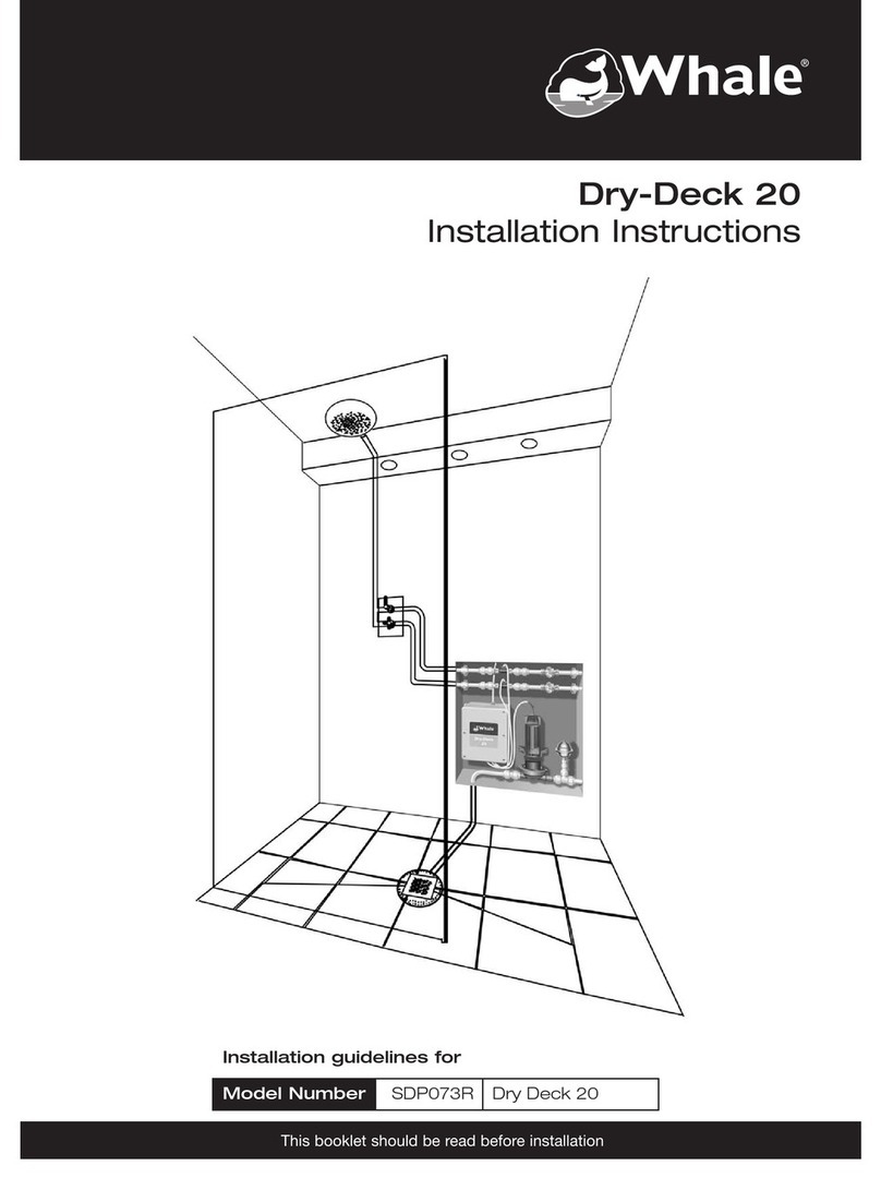
The front cover shows the product installation in an
apartment with the components in an adjacent
room accessed via a cupboard. Assess your
installation prior to fitting so that the pump, surge
damper, control unit and sensors are in accessible
positions.
Typical installations would have these components
in an adjacent cupboard or in a false wall with an
access panel.
Incorrect installation may invalidate warranty.
Principles of Operation

3
Warnings
Before installation read the instructions.
• All electrical and mechanical components
(control unit, surge damper, pump and flow
sensors) must be accessible after installation.
• The maximum flow rate the pump is designed
to work with is 20 ltrs/min.
• Avoid plumbing the pump outlet into the waste
piping that other appliances drain into as there
is a risk of induced syphoning. Use an
antisyphon trap in these situations.
• With installations where the floor is being
formed in the screed, we recommend the
following minimum falls:
30mm in 1m, 15mm in 500cm, 7.5mm in
250cm
• Plumbing installation must comply to latest
WRAS regulations.
• The electrical wiring must conform to EU wiring
regulations BS7671:2008 Part 7 (17th Edition).
• Pipework must be secured to prevent further
vibration and noise.
• It is advisable where the property is unattended
for an extended period that the water supply to
the shower is shut off.
• If there is a reduction in pump performance after
installation please contact your installer.
Installation Warnings
User Warnings
Illustrations
Contents
Pump Installation 4
Plumbing 4
Plumbing of Waste Pipe 5
Plumbing Gulley 6
Control Unit 7
Schematic of Dry-Deck Components 8
Flow Sensor Connection 9
Electrical Connections 10
Pump Setup 11
Flow Restriction 14
Pump Operation 14
Auxilary Functions 15
Plumbing of Waste Pipe 17
Use with a Macerator Pump 17
Fault finding flow chart 18
Declaration of Conformity 20
Specification 20
Component Dimensional Diagrams 21
Dry Deck 20 Components 24
1.1 Pump Orientation 4
1.2 Rotation of Pump Head 4
1.3 Plumbing Pump Head 4
1.4 Pipe Layout Dimensions 5
1.5 Fitting of 50mm Tray Gulley 6
1.6 Control Unit Mounting 7
1.7 Dry Deck Component Connections 8
1.8 Flow Sensor 9
1.9 Connections to Control Unit 10
1.10 Control Panel Settings 11
1.11 Flow Restriction 14
1.12 Pump Head Cross Section 14
1.13 Solenoid Switch 15
1.14 Pump Run Switch 16
1.15 Waste Adaptors 17
1.16 Plumbing to Macerator Pump 17

1.1
1.1 Before mounting the pump refer to the
plumbing diagram opposite for maximum
pipe specification.
Mount the pump on a solid wall to prevent
vibration. Use a back board if this is not
possible.
Note: If mounted to a stud wall pump vibration
may cause noise through the resonance of the
wall. In these situations mount the pump on a
bracket off the floor. The pump may be mounted
horizontally on the floor if required.
Fix the pump in position through the feet with
the fixings provided.
1.2 Rotate the pump head if necessary to give a
straight run of pipe to the waste. Loosen the
clamping ring on the pump head and rotate
the head before retightening clamping ring.
Note: Do not remove the pump head.
Top Tip
To aid servicing the head of the pump must
be above the floor by at least 150 mm
(maximum height of 500 mm).
1.3 Push fit fittings are provided to connect the
pump to inlet and discharge pipework. Push
fit fittings are necessary to aid maintenance
and fault diagnosis. All pipework in and out
of the pump must be in 22 mm.
Ensure fittings are pushed home and locked.
4
Pump Installation
Plumbing
1.2
1.3

1.4
1.4 Only one vertical lift on the inlet to the
pump and one vertical rise from the
discharge from the pump is allowed.
• When laying the pipe under the floor use
only slow radius bends.
• Use slow radius bends above the floor to
ease the flow of water and reduce loading on
the pump.
5
Plumbing of Waste Pipe
Horizontal to waste pipe - To increase pump life
ensure that 1 1⁄4” or 1 1⁄2” pipe is used with a gravity
fall where the pipe length is greater than 1m. If less
than 1m use 22mm pipe.
• Ensure pipe edges are burr-free. Burrs may
cause a build up of hair etc. that will
reduce flow.
• Pipework must be secured to prevent further
vibration and noise.
• Push home and Twist lock the securing ring
on the push fit fittings (If semi rigid pipe is
being used follow the manufacturers
instructions to prevent air leaks).
Inlet and Outlet pipe must always be in 22mm.
Min 1:40 fall

1.5 Gulley Options:
For conventional gulley options for wet floor
and walk in showers see page 22 and 23.
Note: The Gulley must be purchased
separately from your distributor.
Use silicone on top of the seal to ensure
proper sealing beneath the tray. Using the
hand tool provided to tighten the locking
ring. Fit the gulley cover into the sockets and
push down with the palm of your hand to
secure.
When fitting in solid floors, remove enough
concrete for the installation of the pipe and
gulley connections. Where copper pipe runs
under the concrete it must be lined to
protect it and prevent corrosion.
Top Tip
Leave the hand tool in place to prevent
building debris, grout etc. falling into the
gulley. Only remove the hand tool and fit
the gulley cover when the installation is
complete.
6
Plumbing Gulley
1.5a
1.5

1.6 Location of Control Unit:
Locate the control unit outside the showering
area in accordance with BS7671: 2008 Part
7 (17th Edition).
The control unit meets IP45 requirements.
7
Control Unit
1.6a 1.6b
1.6c
Tighten all cable entry grommets, even
unused ones, to seal the Control Unit.
Connect Control Unit to 240V a.c. supply via
an unswitched 5 amp fused spur.

8
Schematic of the Dry-Deck Components
1.7

9
1.7 Flow Sensor
• Fit the flow sensors with the arrow in the
direction of flow to the shower, downstream
of any other connections to the water supply.
• Ensure flow sensor is accessible.
• The flow sensors must be mounted in a
straight length of unstressed pipe.
• Note: For the Sika sensor, a filter is not
required. See Fig 1.8
• Ensure all pipes are pushed home into the
push fit fittings and locked.
• Check all plumbing for leaks whilst the pump
is running.
• Ensure flow sensor is fitted in a length of
unstressed pipe.
Flow Sensor Plumbing
Connection
1.8
Sika sensor
Commissioning Checklist

10
• Switch off the power to the control unit
before making connections.
• Feed wires through cable grommets prior to
connection to the control unit.
• Strip wires 10mm and twist prior to inserting
into spring loaded contracts.
• Push contact arm back with a finger or small
screwdriver before inserting wire fully and
then release.
• Check for a good connection by giving a
gentle tug on the wires.
• Tighten cable grommets after connection.
Wiring Connections:
1. Flow Sensor to Dry-Deck Control Box -
Connect the flow sensor(s) as shown (For
cold supply use FSA and for hot supply use
FSB):
Sika Sensor(s) See Fig 1.9
- White wire to Power (PWR)
- Green to Signal (SIG)
- Brown to Ground (GND)
2. Pump to Dry-Deck Control Box - Connect
Pump Supply Wires as Shown:
- Black wire to PUMP BLACK
- Red wire to PUMP RED
Warning! Avoid fouling the insulation when crimping
to the pump supply wire.
Flow Sensor Electrical
Connections
1.9
Sika sensor Connections

1.9 A simple set up is all that is required for
trouble-free efficient performance of the
Dry-Deck 20 system.
How to Adjust Settings:
a. Pressing the ‘<’ or ‘>’ button will switch
between the various menu options, indicated by
the message on the display.
b. The ‘up’ and ‘down’ arrows are used to adjust
the value.
c. Press OK ‘ ’ key firmly to store value.
Press OK ‘ ’ to enter configuration screens.
Follow the sequence of screens and set values as
required to complete setup.
1. Language: English is the default language. For
other options use ‘up’ and ‘down’ arrows.
2. Sensor Type: Select Sika sensor.
3. Pump Speed:
This sets the speed of the pump in relation to the
flow rate from the sensors.
Prior to making adjustments turn the shower on
and wait until the pump runs. Set the shower flow
rate in the range 6-9 ltrs/min as indicated on the
display.
Note: For pumped showers use the lowest flow rate to
set the Pump speed. This may be outside the band 6-9
ltrs/minute.
Watch the level of water within the shower
using the gulley cover as a guide. If the water
level is falling reduce the speed of the pump by
pressing the ‘down’ arrow. Use initial changes of 5
until fine tuning is required. If the water level is
rising make changes in blocks of 5 to increase the
speed of the pump by using the ‘up’ arrow.
After making a change watch the water level.
Wait at least 30 seconds, as the system
needs to stabilise, until you see if the water is
rising or falling. When the water level is slightly over
pumping, store the speed setting by firmly pressing
the OK ‘ ’ button.
11
Pump Set Up
1.10
Sensor OK
Type SIKA

12
4. Pump Speed - Fine Setting:
This setting is required to fine tune the speed at
flow rates other than that used to set the main flow
rate.
a. Increase the flow from the shower in increments
of 2 litres and watch the water level around the
shower gulley. If this is rising or falling over time
make adjustments until a constant level is
observed then programme in the setting by
pressing the OK ‘ ’
Note: For pumped showers 2ltr increments may not be
possible. se the selections on the shower.
b. Repeat the above process. The narrow
adjustment corrects the flow rate over a band 1
ltr/min either side of the flow rate that is being
calibrated.
When the maximum flow rate is set then proceed
to the next setting by pressing the ‘>’ key.
5. Pump Shut Down:
Over Run (Auto-Sense) Preferred Option
Auto-Sense operates by recognising when the
pump is drawing air through the pump (after waste
water is removed from the tray). This is done by
recording the lowest current taken by the pump as
a limit value. In subsequent shower operations
when this value is reached the pump turns off.
To set the Auto Sense value select this mode, turn
off the shower.
When the pump has removed the water remaining
in the tray the pump current will decrease. When it
has reached the lowest value (by observing when
the value stops falling) press OK ‘ ’ key to
store this value.
Over Run (Time-Delay)
Alternatively to set a fixed Over Run delay select
Time-Delay.
Select value of time delay (in seconds) and store.
6. Start Volume:
This selects the initial amount of water (litres) in
the tray before pumping starts. To minimise noise
the water should be above the level of the gulley.
(Factory default is the minimum setting of
0.6 ltrs). Pressing the up arrow will increase the
amount of water from 0.6 ltrs to 4 ltrs passing
through the shower head before the pump starts.
Make this adjustment during final commissioning.
Pump Set Up (contd.)
Start Delay Select
Volumeá â 1.2Ltrs
Off Delay Select
Timeá â
Over-Run OK
Typeá â TIME-DELAY
Pump Current 81
Limit OK 0
Over-Run OK
Typeá â AUTO-SENSE
A 4 .6 B 5 . 4 A +B10.0
Fine Speedá â +19

13
7. Purge Cycle:
When ON is selected the pump restarts at a low
speed 15 minutes after showering is completed.
This is done to remove run off water that gathers
in the gulley.
In some installations, i.e. ensuite, the client may
wish that the Purge Cycle is disabled by selecting
OFF.
Dry-Deck Review Screens
The following are the status displays that may be
scrolled through when the pump is off:-
System Type and Software Level
Note: To adjust any of the pump settings press OK ‘ ’
Running Time of Pump
Standby Time of Pump
Inlet Pipe Diameter: (Always 22mm For
Dry-Deck)
Flow Sensor Type:-
Factory Default Settings
To return the unit to Factory Default settings start at
the System Type and Software Level Screen.
Press then > six times to get to the screen
asking if factory default settings are wanted. Press
^ to select ‘YES’ and ^ to confirm. The unit will
then be reset to default settings.
Pump Set Up (contd.)
Flow Sensor exit>
Type SIKA
Inlet pipe next<>
Diameter 22mm
Standby next<>
123456hrs 23min
On Time next>
123456hrs 23min
DryDeck V2.3
Review> Adjust
Purge Cycle Select
15 min Cycleá â O N
DryDeck 20 V2.3
Review> Adjust

14
1.10 In installations where the flow rate exceeds
the specification of the Dry-Deck 20, one method
to restrict flow is to insert a flow restrictor in the
outlet of the mixer valve. Where a standard shower
head is not used then pressure reducers may be
used on the hot and cold supply.
Flow Restriction
Pump Operation
1.12
1.11
1.11 The Whale pump uses a single membrane to
pump the water away. On the suction stroke, water
and debris are drawn in through the inlet valve.
With a chamber full of water the pump discharges
the water through the two non-return valves on the
outlet. The two outlet valves protect the pump
against losing prime. The aggressive flushing keeps
the pump valves clear of debris resulting in a pump
which does not require regular maintenance.
Unlike other pumps, the Whale has the ability to
run dry without causing damage to the pump.
An additional advantage of the three non-return
valves, is that no smells can be passed back from
the waste stack into the shower area.

15
1.12a Solenoid Switch:
See diagram 1.13.
The Solenoid SW terminals are to provide water
shut off to the shower by the use of an additional
momentary contact switch and auxiliary solenoid
drive transformer. To use the system the user
closes the momentary contact switch, this causes
Solenoid 1 and Solenoid 2 to be energised for 30
minutes. After the 30 minute period, the shower is
again shut off from the water supply.
Auxilary Functions
Specification for 12V dc Solenoid Driver
Transformer
Part No: SDA421T
Solenoids (Not Supplied with kit)
Momentary contact switch (Not supplied with kit)
1.13

1.12b Pump Run Switch:
See diagram 1.14.
The pump run SW terminals are provided as a
means by which the pump can temporarily be
operated, without the shower operating, using an
additional momentary contact switch. When the
momentary contact switch is pressed the pump
runs for 2 minutes then enters the over run cycle.
This may be used where the wet room is washed
down and water needs to be pumped away.
16
1.14

17
1.13 Where the situation demands or if the waste
pipe run is greater than that specified for the
Whale pump a macerator pump may be used.
Contact the technical helpline (0845 0694 253)
for advice.
The discharge from the pump must go into
the top of the macerator box and not into lower
side entries.
DO NOT USE the bottom entries.
Note: Where a macerator is used in a bathroom it is
preferable to run a separate discharge from the Dry-
Deck pump to the waste. This reduces noise as the
macerator will run intermittently while the shower is
running if used in conjunction with the Dry-Deck.
Warning: Any failure of the macerator will not
be detected by the Whale pump.
Use with a Macerator Pump
1.16
From pump
Plumbing of Waste Pipe
• The outlet of the pump may be connected
into the waste pipe, e.g. former bath waste.
Black rubber fittings are provided for this.
• In confined bathrooms pump discharge may
go into the sink waste pipe using suitable
adaptors. See Fig 1.15 for McAlpine
examples and their catalogue for other
variants.
1.15
C10V V33T

18
Repeat Set up. If pump
does not turn off, contact
Customer Service for
further diagnostics.

19
Notes

20
Description of Equipment: Shower Drain System
Manufacturer’s Declaration
We hereby declare, under our sole responsibility,
that the above equipment complies with the
provisions of the following EC Directives.
Electromagnetic Compatibility Directive
2004/108/EC, on the approximation of the laws of
the Member States relating to electromagnetic
compatibility.
Low Voltage Directive 2006/95/EC on the
harmonization of the laws of the Member States
relating to electrical equipment designed for use
within certain voltage limits.
CE mark first affixed: 01/01/96
Basis on which conformity is declared
The above equipment complies with the protection
requirements of the EMC Directive and the
principal elements of the safety objectives of the
Low Voltage Directive.
Standards applied
EN 60335-1:2001/A2:2006 Safety of household
and similar electrical appliances
EN 60335-2-41:2003/A1:2004 Particular
requirements for pumps
EN 55014-1:2000/A2:2002 Electromagnetic
compatibility.
Requirements for household appliances, electric
tools and similar apparatus. Emission
EN 55014-2:1997/A1:2001 Electromagnetic
compatibility.
EU Declaration of Conformity
Requirements for household appliances, electric
tools and similar apparatus. Immunity.
Signed
Richard Bovill
Engineering Director
Dry Deck Unit
Model: 755.241
Power rating 137VA
Double insulated
Mains cable 3.0m
3 core 0.75mm26A
6.3 amp fast blow fuse
Please see the enclosed warranty statement.
2017 WHALE All rights reserved.
Reproduction in whole or in part without permission is
prohibited. WHALE® is a registered
trademark of Munster Simms Engineering Limited.
Whale’s policy is one of continuous improvement and
we reserve the right to change specifications without
prior notice. Illustrations are for guidance purposes only.
Neither the accuracy nor completeness of the
information contained in this or any Product literature is
guaranteed by the Company and may be subject to
change at its sole discretion.
Specification
Warranty
Trademarks/Copyright
Table of contents
Other Whale Plumbing Product manuals
Popular Plumbing Product manuals by other brands

Hans Grohe
Hans Grohe AXOR Starck 10859 0 Series Installation/User Instructions/Warranty

Toto
Toto TLP02301 Operation manual

KWC
KWC ACXX2021 Installation and operating instructions

Axor
Axor Brushed Nickel 28514821 Specification sheet

Kohler
Kohler Triton K-T7019 installation guide

saunalife
saunalife Ergo E7 Series manual

Elson
Elson BUSHPEX Product information and installation manual

Clou
Clou Kaldur CL/06.05.004.41.R installation instructions

Spectrum Brands
Spectrum Brands Pfister Masey 8P8-WS2-MCSC Quick installation guide

Toto
Toto TBV03429B installation manual

Tres
Tres STUDY 26285301AC manual

Graff
Graff ATLANTIS 1100-C2 installation instructions