Whalen XL-33E User manual

THIS INSTRUCTION BOOKLET CONTAINS IMPORTANT SAFETY INFORMATION.
PLEASE READ AND KEEP FOR FUTURE REFERENCE.
Date 2017-04-06 Rev. 0001-B Factory: TANBOD
3-in-1TM Flat Panel Console
Stock # XL-33E
U.S. Patent 8,561,551
This item is designed to be a 3-in-1 configuration. Please choose the option that best suits your
needs. DO NOT discard any of the hardware or parts that you will not use on your chosen option.
This will allow you to use this TV Console in different configurations at a later date, if desired.
ADULT ASSEMBLY REQUIRED
If you have any questions regarding assembly or if parts are missing, DO NOT return this item to
the store where it was purchased. Please call our customer service number and have your
instructions and parts list ready to provide the model name, part name or factory number:
866-942-5362
Pacific Standard Time: 8:30 a.m. - 4:30 p.m., Monday - Friday
Or visit our web site 24 hours a day, 7 days a week for product assistance at
www.whalenstyle.com
Or e-mail your request to parts@whalenfurniture.com
LOT NUMBER:
DATE PURCHASED: / /
TV
TV

2
MANUFACTURER: Whalen Furniture Manufacturing
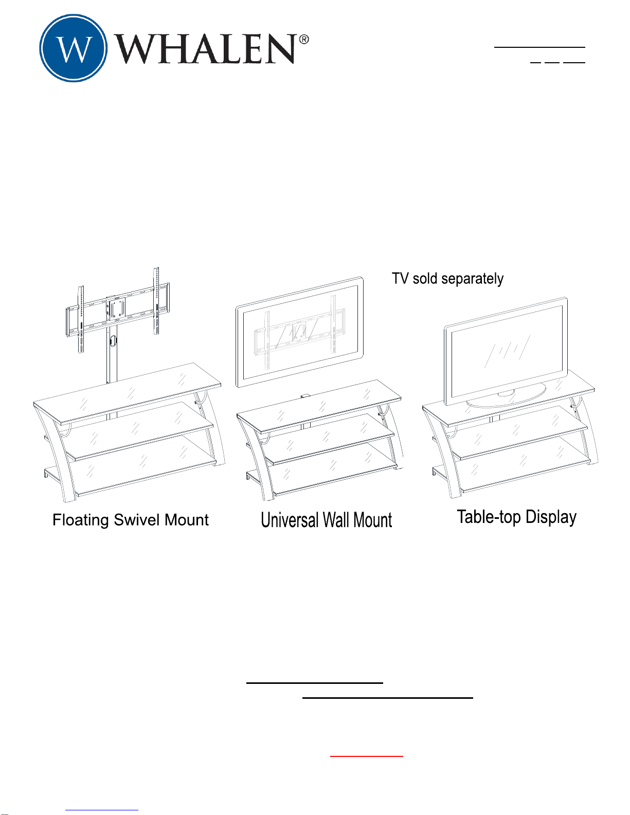
CATALOG: 3-in-1TM Flat Panel Console
MODEL # XL-33E
MADE IN CHINA
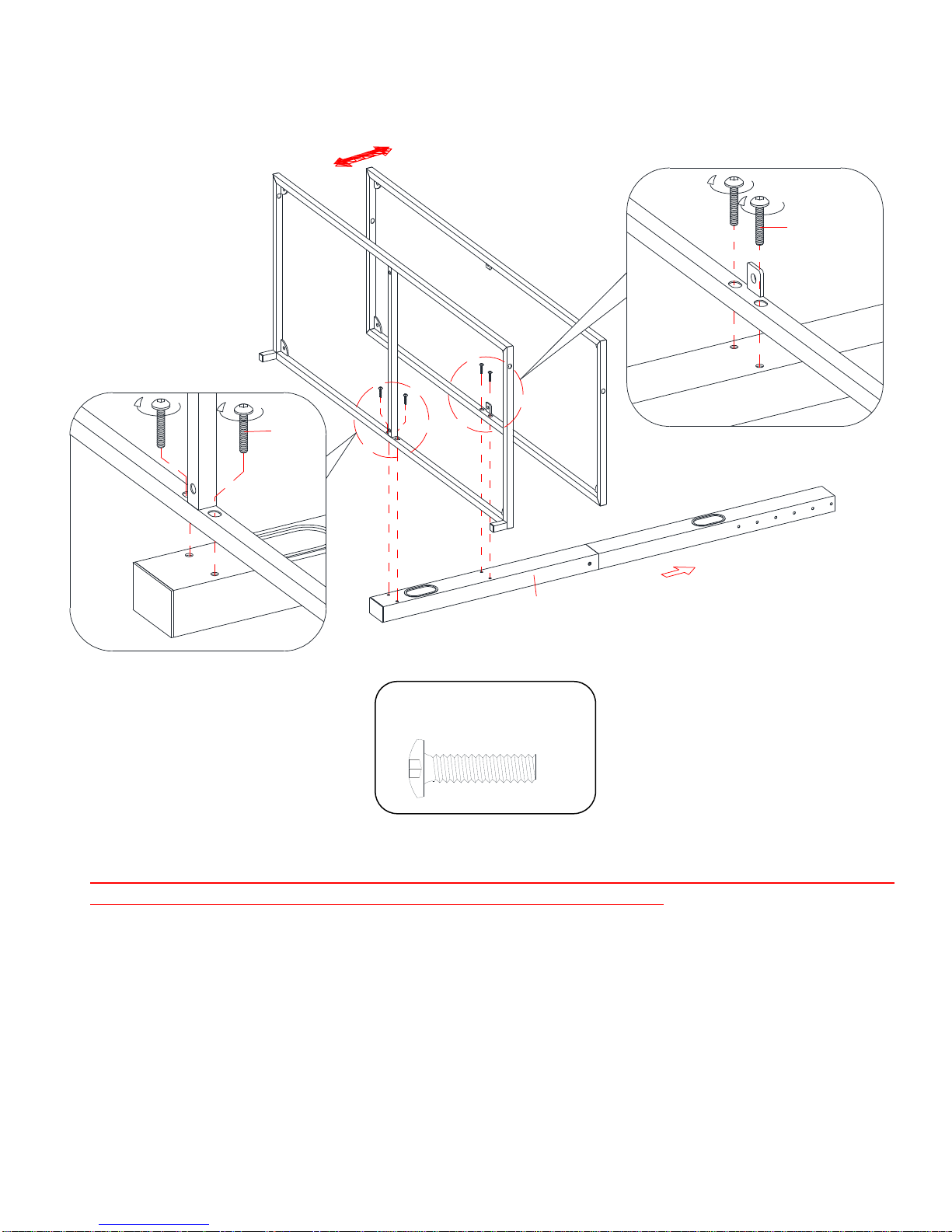
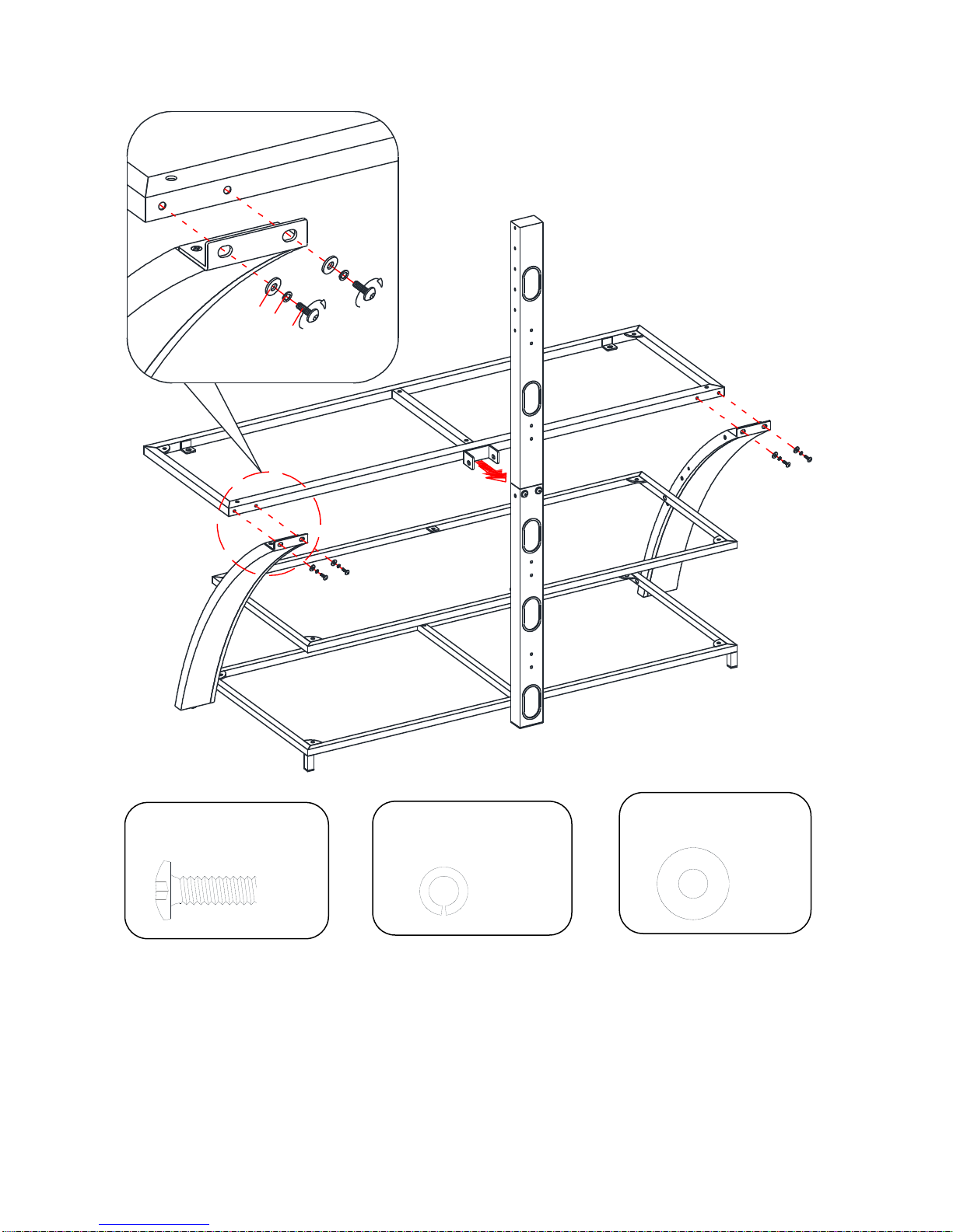
1. Please read the Assembly Instructions prior to assembling this product.
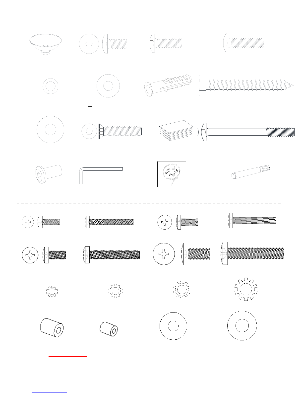
2. Remove all hardware from the box and sort by size.
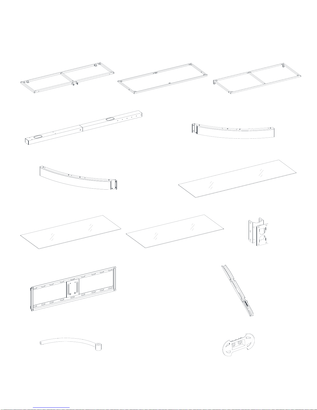
3. Check to see that all hardware and parts are present BEFORE assembling.
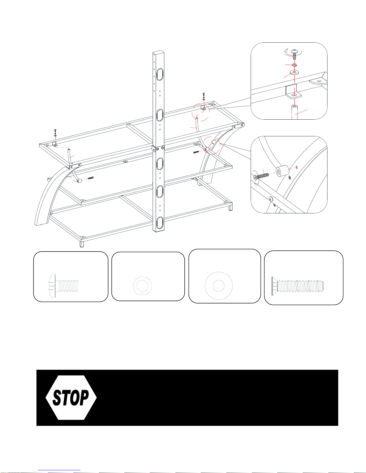
4. Ask a friend to assist you with the assembly of this furniture.
5. To avoid damage, assemble the product on a sturdy, level and protective surface.
6. Please wait until all steps are completed before fully tightening bolts.
7. Make sure all bolts are tightly fastened before the unit is used.
MAXIMUM RECOMMENDED WEIGHT LOADS
GENERAL INFORMATION, TIPS AND TRICKS
FITS UP TO MOST 177.8 cm / 70 in FLAT PANEL TVs
MAXIMUM LOAD 61.2 kg / 135 lb
FITS UP TO MOST 165 cm / 65 in FLAT PANEL TVs
WITHOUT SWIVELING BRACKET
MAXIMUM LOAD 61.2 kg / 135 lb
MAXIMUM LOAD 22.6 kg / 50 lb
This product is sold with one set of Tipping Restraint Hardware Kit. You must install the Tipping
Restraint Hardware between the wall and the TV console to prevent any accidents or
damages. When properly installed, this restraint can provide protection against the unexpected
tipping of the unit due to small tremors, bumps or climbing. The restraint is only a deterrent and
is not a substitute for proper adult supervision. Use of tip-over restraints may only reduce, but
not eliminate, the risk of tip-over.
THIS UNIT IS NOT INTENDED FOR USE WITH CRT TVS. USE ONLY
WITH FLAT PANEL TVS AND AUDIO/VIDEO EQUIPMENT MEETING RECOMMENDED SIZE
AND WEIGHT LIMITS. NEVER USE WITH LARGER/HEAVIER THAN RECOMMENDED FLAT
PANEL TVS OR EQUIPMENT. TO AVOID INSTABILITY, PLACE FLAT PANEL TV IN THE
CENTRE OF THE UNIT; THE BASE OF THE TELEVISION MUST BE ABLE TO REST ON THE
SUPPORTING SURFACE OF THE UNIT WITHOUT OVER-HANGING THE EDGES.
IMPROPERLY POSITIONED FLAT PANEL TVS, OR FLAT PANEL TVS OR OTHER
EQUIPMENT THAT EXCEED RECOMMENDED SIZE AND WEIGHT LIMITS COULD FALL OFF
OR BREAK THE UNIT, CAUSING POSSIBLE SERIOUS INJURY.

3
Parts and Hardware List
Please read completely through the instructions and verify that all listed parts and hardware
are present before beginning assembly.
A- Top Shelf Frame (1) B- Middle Shelf Frame (1) C- Bottom Shelf Frame (1)
D- Spine Assembly (1) E- Left Leg (1)
F- Right Leg (1) G- Top Glass (1)
H- Middle Glass Shelf (1) I- Bottom Glass Shelf (1) J- Swiveling Bracket (1)
K- Mounting Frame (1) L- Monitor Bracket (2)
M- Top Shelf Support (2) N- Cable Wheel (2)

4
Parts and Hardware List
(1) Suction Cup (2) 1/2” Bolt (3) 3/4” Bolt (4) 1” Bolt
(18+1 extra) (6+1 extra) (16+1 extra) (8+1 extra)
(5) Lock Washer (6) Flat Washer (7) Concrete Anchor (8) 2-1/2” Lag Bolt
(18+1 extra) (18+1 extra) (4) (4)
(9) Lag Bolt Washer (10) 1-1/8” Flat Head Bolt (11) Spine End Cap (12) 2-1/2” Bolt
(4+1 extra) (2+1 extra) (1) (1)
(13) Flange Nut 4 mm Hex Wrench Tipping Restraint Hardware Kit (1) Touch-up Pen
(1) (2) (Inside Plastic Bag) (1)
TV Mounting Kit
M4 x 12 Bolt (4) M4 x 30 Bolt (4) M5 x 12 Bolt (4) M5 x 30 Bolt (4)
M6 x 12 Bolt (4) M6 x 35 Bolt (4) M8 x 16 Bolt (4) M8 x 40 Bolt (4)
M4 Lock Washer (4) M5 Lock Washer (4) M6 Lock Washer (4) M8 Lock Washer (4)
Large Spacer (4) Small Spacer (4) M4/M5 Flat Washer (8) M6/M8 Flat Washer (4)
Tools required: Hex wrench (provided) and Phillips screwdriver (not provided).

5
Assembly Instructions
NOTE: Please do not fully tighten all bolts until you finish assembling all parts. Once assembled,
go back and fully tighten all bolts. This will make the assembly easier.
1. Unpack the unit and confirm that you have all the hardware and required parts.
2. Locate the Spine Assembly (D) and set back face down on a scratch free surface, as shown.
3. Align and attach 2 lower Shelf Frames (B and C) to the Lower Spine with four 1” Bolts (4). Make
sure that the inside corner plates on the shelf frames will face up when the unit is turned upright.
1”Bolt
(4 used in this step)
④
4
UP
D
B
C
D
CD
B4

6
Assembly Instructions
4. Align and attach the Left Leg (E) to the Lower Shelf Frames (B and C) by inserting two 1” Bolts
(4) from inside the Shelf Frames through the pre-drilled holes on side rail and screw into the
threaded sockets on the Leg. DO NOT tighten the bolts.
5. Repeat last step with the Right Leg (F).
1”Bolt
(4 used in this step)
④
E
F
C
B
D
4
B/C
E/F

7
Assembly Instructions
6. Stand the unit upright.
7. Align and attach the Top Shelf Frame (A) to the Legs (E and F) with the inside corner plates
facing up, using four 3/4” Bolts (3) with the Washers (5 and 6) through the end bracket holes
of the Legs and screw into the back sockets of Top Shelf Frame (A).
3/4” Bolt
(4 used in this step)
③
Lock Washer
(4 used in this step)
⑤
Flat Washer
(4 used in this step)
⑥
D
A
F
E
E/F
A
3
5
6

8
Assembly Instructions
8. Align and attach one Top Shelf Support (M) to the “L” bracket on Top Shelf Frame (A) using a
1/2” Bolt (2) with the Washers (5 and 6). Secure the Top Shelf Support (M) to the Left Leg (E)
with the provided 1-1/8” Flat Head Bolt (10).
9. Repeat the same procedure to attach the other Top Shelf Support (M) at the other end.
10.Go back and tighten all bolts with the provided 4 mm hex wrench
If you choose Table-top Console
configuration, continue to the next step.
If mounting TV with the Floating Swivel
Mount, skip ahead to PAGE 14.
1/2” Bolt
(2 used in this step)
②
Lock Washer
(2 used in this step)
⑤
Flat Washer
(2 used in this step)
⑥
2
5
6
F
E
AM
M
E/F
M
10
AM
1-1/8”Flat Head Bolt
(2 used in this step)
⑩

9
Assembly Instructions for Table-top Console
11.At the back side of the Spine Assembly (D), unscrew the two bolts and the washers to remove
the Upper Spine. So that you can use the table top console configuration.
NOTE: Keep the Upper Spine and the fasteners at a proper place in case you will use the
floating swivel mount.
D
D

10
Assembly Instructions for Table-top Console
12.Plug the Spine End Cap (11) all the way into the top of the Lower Spine (D).
13.Secure the Top Shelf Frame (A) to the Lower Spine (D) by inserting one 2-1/2” Bolt (12) with
the Washers (5 and 6) through the bracket hole and securely screw into the Flange Nut (13).
Lock Washer
(1 used in this step)
⑤
Flat Washer
(1 used in this step)
⑥
2-1/2”Bolt
(1 used in this step)
⑫
D
D
A
A
11
D
13
12
5
6
D
A
Flange Nut
(1 used in this step)
⑬
Spine End Cap
(1 used in this step)
⑪

11
Assembly Instructions for Table-top Console
14.Attach 2 Cable Wheels (N) to the backside of the Lower Spine (D) with the 3/4” Bolts (3).
Tighten the bolts with the provided hex wrench.
15.The Cable Wheels (N) enable you to shorten, separate and route cables and cords. Using the
Cable Wheels, you can create a system for routing cables through channels, between
components and to power sources without tangled mess or annoying signal interference.
3/4” Bolt
(4 used in this step)
③
D
A
N
3
D

12
Assembly Instructions for Table-top Console
16.Put the Suction Cups (1) firmly into top holes and inside corner plates on 3 Shelf Frames (A, B
and C), as shown.
TIP: If a Suction Cup resists insertion, try pressing down on the middle of the cup with the hex
wrench while twisting it clockwise into the hole.
17.Place the Top Glass (G) and Glass Shelves (H and I) in place beginning with the Bottom
Glass Shelf (I), as shown above. Make sure that the glass shelf is properly centered. Push
each glass shelf all the way back against the Spine. Also, be sure to press down evenly and
firmly each glass shelf onto the Suction Cups to make sure they securely rest onto the Suction
Cups.
Suction Cup
(18 used in this step)
①
1
A/B/C
G/H/I
H
I
A
B
C
G
E
F

13
Assembly Instructions for Table-top Console
Tools required: Hex wrench (provided), Phillips screwdriver, mallet, power drill, and 3/8” drill Bit
(not provided).
18.Position the assembled console at the desired location against a wall. In case of uneven floor,
Floor Levelers are provided at the bottom of both Legs (E and F). Simply tilt the unit back and
raise or lower Floor Leveler by hand to correct tilting, as shown above.
NOTE: YOU MUST USE THIS TIPPING RESTRAINT TO ATTACH THIS UNIT TO THE WALL,
TO PREVENT THE UNIT FROM TIPPING, CAUSING ACCIDENTS AND/OR INJURIES.
19.Now, follow the instructions printed on the plastic bag containing the Tipping Restraint
Hardware to attach the tip-over restraint to the Spine and the wall.
20.The console is now ready for use. Be sure to position your Flat Panel TV in the center of the
console.
NOTE: If you choose the Wall Mount configuration, proceed to PAGE 21.
E/F
TV

14
21.Secure the Top Shelf Frame (A) to the Spine Assembly (D) by using two 3/4” Bolts (3) and two
Washers (5 and 6), as shown above.
Assembly Instructions for
Floating Swivel Mount
D
356
3
5
6
A
3/4” Bolt
(2 used in this step)
③
Lock Washer
(2 used in this step)
⑤
Flat Washer
(2 used in this step)
⑥

15
Assembly Instructions for Floating Swivel Mount
22.Fasten the Swiveling Bracket (J) to the top of Spine (D) with six 3/4” Bolts (3) and six
Washers (5 and 6). Make sure that the pivoting bolt head faces up.
NOTE: The Spine can provide four height options for the TV set. Refer to your TV size and
adjust the Swiveling Bracket to the desired height for optimum viewing.
J
356
3
5
6
UP
D
J
3
5
6
356
D
3/4” Bolt
(6 used in this step)
③
Lock Washer
(6 used in this step)
⑤
Flat Washer
(6 used in this step)
⑥

16
Assembly Instructions for Floating Swivel Mount
23.Hold and attach the flat side of the Mounting Frame (K) onto the Swiveling Bracket (J) using
four 1/2” Bolts (2) and four Washers (5 and 6). Make sure that the recess holes on the
Mounting Frame are at the bottom.
K
J
D
BACK
K
2
5
6
5
622
5
6
JD
1/2” Bolt
(4 used in this step)
②
Lock Washer
(4 used in this step)
⑤
Flat Washer
(4 used in this step)
⑥

17
Mounting Monitor Brackets to a Television with a Flat Back
NOTE: For televisions with a curved or recessed back, proceed directly to next page.
24.Determine the correct diameter of the bolt the TV requires by hand threading them into the
threaded insert on the back of the TV. If you encounter any resistance, stop immediately. If
you are unable to find the correct bolt, consult a local hardware store.
25.Follow the appropriate diagram above to attach the Monitor Brackets (L) to the back of the TV
with selected fasteners. Make sure the Monitor Brackets are centered and level with each
other. Secure the bolts with a Phillips Screwdriver. DO NOT over tighten the bolts.
NOTE: Lean the TV up against a wall or other solid surface when attaching the Monitor
Brackets. DO NOT place the TV face down on the glass as this may cause permanent damage.
NOTE: If mounting your TV in the Wall Mount configuration, once you have completed the
installation of the monitor brackets, proceed to PAGE 21

18
Mounting Monitor Brackets to a Television with a Curved/Recess Back
26.Determine the correct diameter of the bolt the TV requires by hand threading them into the
threaded insert on the back of the TV. If you encounter any resistance, stop immediately. If
you are unable to find the correct bolt consult a local hardware store.
27.Follow the appropriate diagram above to attach the Monitor Brackets (L) to the back of the TV
with selected fasteners. Make sure the Monitor Brackets are vertically centered and level with
each other. Secure the bolts with a Phillips Screwdriver. DO NOT over tighten the bolts.
NOTE: Lean the TV up against a wall or other solid surface when attaching the Monitor
Brackets. DO NOT place the TV face down on the glass as this may cause permanent damage.
NOTE: If mounting your TV in the Wall Mount configuration, once you have completed the
installation of the monitor brackets, proceed to PAGE 21

19
Assembly Instructions for Floating Swivel Mount
MAKE SURE ALL BOLTS ARE TIGHT AND THE SPINE IS AT A 90 DEGREE ANGLE
AND USE A QUALITY LEVEL TO VERIFY THE MOUNTING FRAME IS LEVEL PRIOR
TO INSTALLATION OF TV.
28.Once the Monitor Brackets (L) are attached onto the back of television, ask for assistance to
lift the television up to hang the Monitor Brackets (L) onto the Mounting Frame (K). Set the
hooks on the Monitor Brackets over the Mounting Frame and then lower them onto the bars of
the Mounting Frame.
NOTE: Loosen the Lock Bolt that is pre-attached to the Monitor Brackets to ensure an easy fit
at the bottom hooks.
29.Center the television and tighten both Lock Bolts with a long Phillips screwdriver until they hit
the underside of the Mounting Frame (K) to ensure your TV is safe and secure.
1
2
K
L
L
K
K
L
L

20
Assembly Instructions
Tools required: Hex wrench (provided), Phillips screwdriver, mallet, power drill, and 3/8” drill Bit (not
provided).
30.Repeat steps 14 through 17 to attach the Cable Wheels (N) and install the Glass
Shelves (G, H and I) in place.
31.Carefully move the console and position in your desired location against a wall. Now follow the
instructions printed on the plastic bag containing Tipping Restraint Hardware Kit to attach the
tip-over restraint to the Spine (D) and the wall.
NOTE: You must install the Tipping Restraint Hardware with the unit in use to prevent any
accidents or damage to the unit.
32.The console is now ready for use. Swivel the TV left-or-right for optimum viewing control.
TV
E/F
Table of contents
Languages:
Other Whalen TV Mount manuals
Popular TV Mount manuals by other brands

GEM
GEM GEM L-NH2500 instructions

CONTINENTAL EDISON
CONTINENTAL EDISON CE600FX12 Mounting instructions

Rawinternational
Rawinternational PT1 instruction manual

Innovative
Innovative 3500 installation instructions

Sanus
Sanus VisionMount MC1A user manual

PEERLESS Mounts
PEERLESS Mounts SUF650P Installation and assembly