WHD AMP 550/100V User manual

USERMANUAL
AMP550/100V
Multichannel Amplifier
WilhelmHuber+Söhne
GmbH+Co.KG
Manual AMP 550/100V - Technical modifications reserved 29.07.10/WP

2
1.Security Precautions
◎ Carefully to READ the instruction in this manual before use.
◎ Certainly to OBSERVE the INSTRUCTION in this manual regard convention of safety
symbols and messages.
◎ Please KEEP this user MANUAL nearby for anytime reference.
Safety symbol and Message Conventions
Below-described safety symbol and messages are to prevent bodily injury and property
damage. Before operating the amplifier, read this manual first so you completely knowing
the potential safety hazard and understanding the meaning of the safety symbols and
messages.
WARNING Indicates a potentially hazardous situation, which, if
mishandled, could result in death or serious body
injury, and/or property damage.
CAUTION Indicates a potentially hazardous situation, which, if
mishandled, could result in moderate or minor body
injury, and/or property damage.
PANEL DESCRIPTION
■ When Installing the Amplifier
zDO NOT installing or mounting the amplifier in unstable locations, such as on the
rickety table or the slanted surface. It may result in the amplifier falling down
and causing body injury and/or property damage.
zBe sure to ground to the safety ground (earth) terminal to avoid electric shock.
Never to ground to a gas pipe for tragic disaster may occur.
zUse the amplifier only with the voltage specified on the amplifier. Using the voltage
higher than specified may cause fire or electric shock.
zDO NOT cut, twist, damage, nor modify the power supply cord. In addition, avoid
using the power cord close to heaters, and don’t place heavy object, including
the amplifier itself, on the power cord, for it may cause fire or electric shock.
zDO NOT expose the amplifier to rain or the environment where it may be splashed by
water or other liquids, for doing so, it may cause fire or electric shock.
WARNING

- 3 -
When using the Amplifier
zWhen found following irregular situation during amplifier is in use, immediately switch off
the power, disconnect the power supply plug from the AC outlet. Don’t try to operate
the amplifier again. Contact your local dealer to check the amplifier.
9The amplifier falls.
9Amplifier is malfunction.
9Water or any metallic object gets into the amplifier.
9The smoke or strange smell coming from the amplifier.
9The power supply cord is damaged, such as exposure of the core, disconnection etc..
zDO NOT put cups, bowls, or other containers with liquid or metallic object in it on the
top of the amplifier. If they spill accidentally into the amplifier, it may result in
fire or electric shock.
zDO NOT touch the power supply plug during thundering and lightning, for it may result
in electric shock.
zDO NOT insert or drop the metallic objects or flammable materials into the ventilation
slots of the amplifier, for it may result in fire or electric shock.
zDO NOT open nor remove the amplifier cover to prevent fire or electric shock, for there
are high voltage components inside the amplifier.
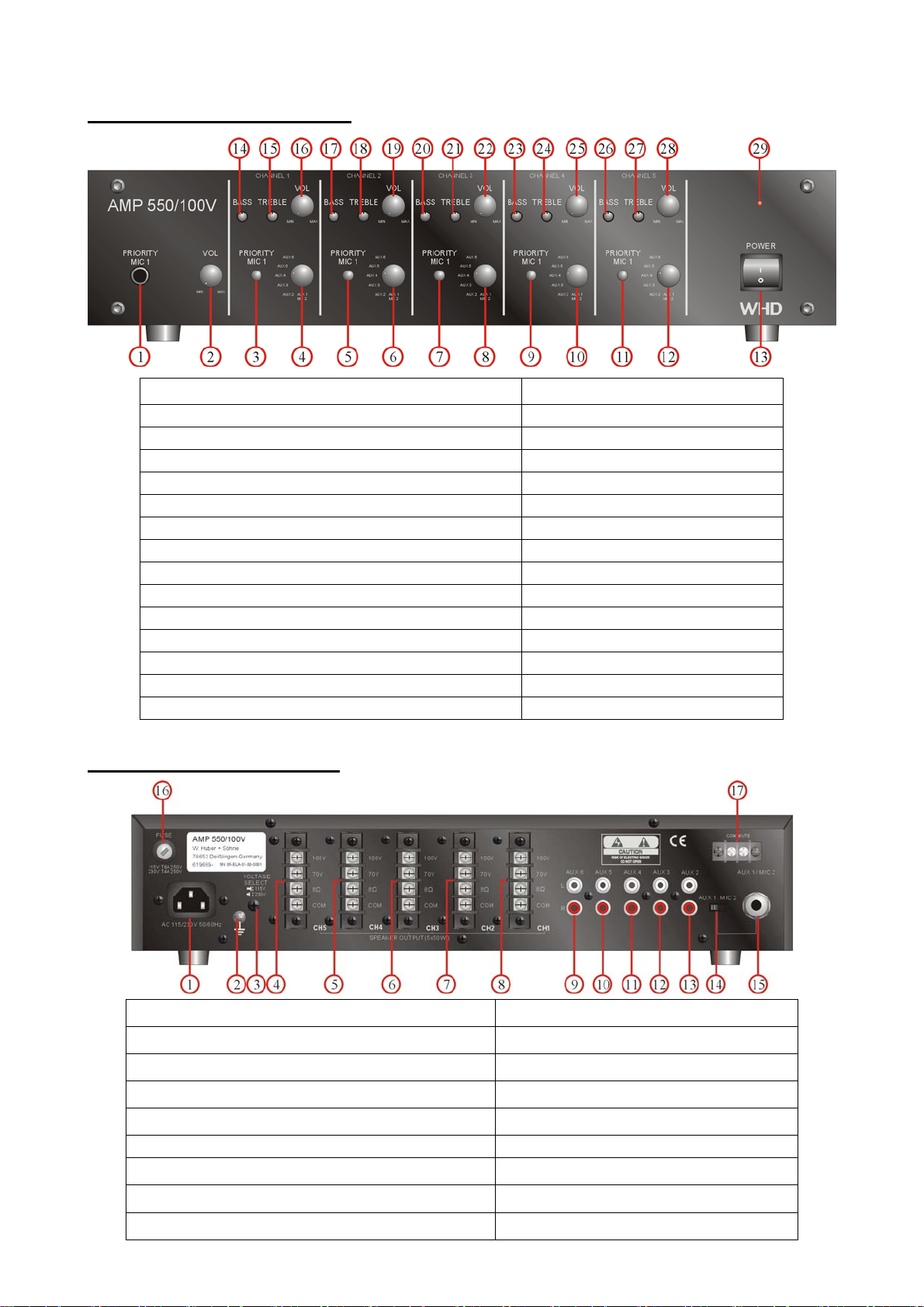
PANEL DESCRIPTION
■ When Installing the Amplifier
zDO NOT remove nor plug in the power supply plug with wet hands, for it may cause
electric shock.
zWhen unplug the power supply cord, be sure to grasp the power supply plug. DO
NOT pull on the cord itself. Operating the amplifier with damaged power
supply cord may cause fire or electric shock.
zAvoid installing the amplifier in humid or dusty places, the area exposed to the direct
sunlight, locations generating smoke or steam, or the spot near the heaters.
It may result in fire or electric shock.
zWhen moving the amplifier, be sure to remove its power supply cord from the wall
outlet. Moving the amplifier with the power cord connected to the outlet may
cause damage to the power cord, and resulting in fire or electric shock.
When removing the power cord, be sure to grasp its plug to pull.
zDO NOT block the ventilation slots of the amplifier chassis. It will cause the
temperature rising and result in fire.
CAUTION

4
■ When Using the Amplifier
zMake sure that the volume control is turned to minimum position before power is
switched on. Loud sound produced at high volume when power is switched
on may impair hearing.
zDO NOT place heavy objects on the amplifier, for it may cause it fall and may result in
body injury and/or property damage. Besides, the object itself may cause
damaged or body injury.
zDO NOT operate the amplifier for the extended period of time with the sound distorting.
It is an indication of malfunction, which can cause heat and result in fire.
zSwitch the power off, and unplug the power supply plug from theAC outlet for safety
purposes, when cleaning or leaving the amplifier unused for 7 days or more.
Fire or electric shock may occur.
zIf the dust accumulates on the power supply plug or in the wall AC outlet, fire may
result in. Clean it periodically. In addition, make sure the plug is inserted in
the wall outlet securely.
zContact your local dealer to clean the dust, it the dust has accumulated in the amplifier
for a long period of time. Dust accumulation may result in fire or damage.
2. Description
AMP 550/100 is the mixer amplifier designed for up to 5 channels (zones) application.
Each channel output is 50W RMS. And each one has its own bass, treble, and level
(volume) control. There are 7 input sources: MIC1 + MIC2/AUX 1 + AUX 2~ 6.
The front MIC. 1 input has the voice priority function with level control. Each channel has
one push switch to select to mute its own signal source or not.
To ensure the amplifier safety, it has speaker short, over temperature, and overload
protection.
The output connection is 8 ohm, 70V, and 100V screw terminal.
It acceptsAC 115V/230V 50/60 Hz.
AMP 550/100 is the ideal mixer amplifier for multi-zone with multi sources.

- 5 -
3. Panel Description
FRONT PANEL DESCRIPTION
1. MIC. 1 Input 16. Channel 1 Volume Control
2. MIC. 1 Volume Control 17. Channel 2 Bass Control
3. Channel 1 Mute Priority Switch 18. Channel 2 Treble Control
4. Channel 1 Input Source Selection Switch 19. Channel 2 Volume Control
5. Channel 2 Mute Priority Switch 20. Channel 3 Bass Control
6. Channel 2 Input Source Selection Switch 21. Channel 3 Treble Control
7. Channel 3 Mute Priority Switch 22. Channel 3 Volume Control
8. Channel 3 Input Source Selection Switch 23. Channel 4 Bass Control
9. Channel 4 Mute Priority Switch 24. Channel 4 Treble Control
10. Channel 4 Input Source Selection Switch 25. Channel 4 Volume Control
11. Channel 5 Mute Priority Switch 26. Channel 5 Bass Control
12. Channel 5 Input Source Selection Switch 27. Channel 5 Treble Control
13. Power Switch 28. Channel 5 Volume Control
14. Channel 1 Bass Control 29. Power Indicator - LED
15. Channel 1 Treble Control
REAR PANEL DESCRIPTION
1. AC Power Input Socket 9. AUX 6 input (RCA jack)
2. Earth Ground Connection Screw 10. AUX 5 input (RCA jack)
3. AC Voltage (115V/230V) Selection Switch 11. AUX 4 input (RCA jack)
4. Channel 5 Output Screw Terminal 12. AUX 3 input (RCA jack)
5. Channel 4 Output Screw Terminal 13. AUX 2 input (RCA jack)
6. Channel 3 Output Screw Terminal 14. AUX 1/MIC 2 Selection Switch
7. Channel 2 Output Screw Terminal 15. AUX 1/MIC 2 Input
8. Channel 1 Output Screw Terminal 16. AC Fuse
17. General mute

6
4.Features
zUp to 5 channels (zone)
z6 selectable input sources + MIC 1 (First Priority)
zBass, treble, and volume control for each channel
zVoice priority function on MIC. 1
zOverload, over temperature, and speaker short protection.
z8 ohm, 70V, and 100V output
zAC power in
z2U height
z19” rack or table mounted
5. Power Source
zAC Power Source
The supply transformer has been designed for use on either 115V or 230V, (50-60Hz),
selected by a push switch on the rear panel. The amplifier is factory set at 230Vac mains
voltage. When you switch the amplifier to 115V , the internal fuse must must be changed
from 4 to 8 amp.
6. Connection
zMicrophone Connection
Mic1~2 inputs are unbalanced standard 1/4” Phone Jack.
Mute Function
Priority Microphone, Mic1 input has VOX priority over CH 1~5. Press the push switch of
each channel on the front panel to mute the corresponding signal source.
General Mute Function
Input at the backside for mute of all 5 channels. Use potential free relay contact.

- 7 -
AUX Connection (Input)
The equipment provides 5 auxiliary inputs which may be used for connecting other signal
sources such as a Radio Tuner, CD or Cassette player. A slide switch is located near by
AUX1/MIC 2 on the rear panel for selection of MIC2 or AUX1. AUX 2 ~ 6 inputs are a dual
RCA jack and have a stereo to mono converter for each channel
SLEEVEPIN
RCA plug connector
zOutput Connection
There are 5 speaker output terminals on the rear panel. Each terminal has 3 speaker
outputs: 8 ohm, 70V and 100V. Use only one of these outputs for connection.
7. Operation
After all connections are completed, turn the Input Source Selection Switch of each channel
to set on the corresponding position for the signal source. If necessary, turn the bass, treble,
and volume control to what you desire.
Before using the microphone 1 on the front panel to broadcast, make sure the level (volume)
control of MIC 1 is at proper position (not at maximum position). Set the push switch of
each channel to control the mute function of its own channel signal source. Switch-down is
to mute signal source, only the voice from MIC 1 can be heard, while switch-up does not
mute signal source, both voice from MIC 1 and channel signal can be heard. If necessary
to adjust the volume further, turn the level control of MIC 1 and/or of Channel 1 ~ 5.
Information for Users on Collection and Disposal of Old Equipment and used
Batteries
This product and batteries should not be mixed with general household waste. For proper
treatment, recovery and recycling take them to applicable collection points, in accordance
with your national legislation and the Directives 2002/96/EC and 2006/66/EC.
By disposing these products and batteries correctly, you will help to save valuable resources
and prevent any effects on human health and the environment which could otherwise arise
from inappropriate waste handling.
For more information about collection and recycling of old products and batteries, please
contact your local municipally, your waste disposal service or the point of sale where you
purchased the items. Penalties may be applicable for incorrect disposal of this waste, in
accordance with national legislation.

8
8. Technical Specification
Model AMP 550/100V
Type Multichannel Amplifier
Power Supply
AC 115V/ 230V, 50 / 60Hz ± 10%
Switchable
Output Power: 50W x 5
Total Harmonic Distortion <= 0.1% @ 1KHz, rated power
Sensitivity 1/4" PHONE JACK (UNBALANCED)
MIC 1~2 1 mV @ 600 ohm
AUX 1 700mV @ 20K ohm
RCA JACK (UNBALANCED)
AUX 2~6 700mV @ 20K ohm
Frequency Response 50Hz ~ 15KHz ± 3dB
Output 100V, 70V, 8 ohm; screw terminal
Signal to noise ratio > 70dB
Voice Priority Mute MIC. 1
Protection Speaker Short
Temperature
Overload
AC power consumption 640W @ rated power
Dimensions ( H x W x D )mm 88 (H) x 425(W) x 345 (D) mm
Weight 15 kgs
Mounting Free standing or 19” rack
WARNING: THIS APPLIANCE MUST BE EARTHED
Table of contents
Other WHD Amplifier manuals